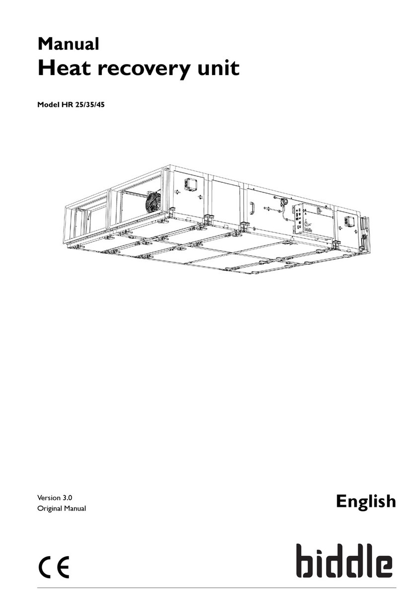
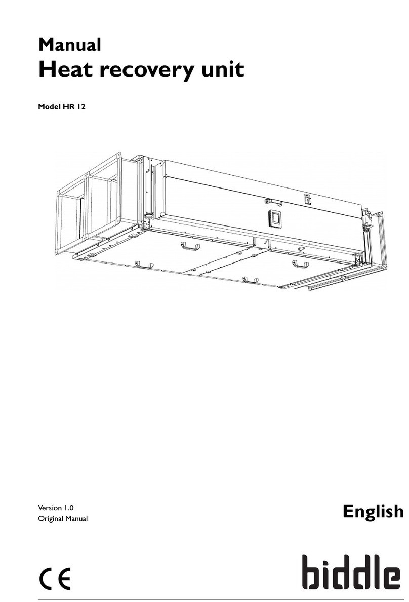
Biddle PRO270 Assembly instructions

Issue: 1.1
PRO270 Fan Coil Unit
INSTALLATION, OPERATING AND
MAINTENANCE INSTRUCTIONS
Original Instructions

Page 2
Copyright and trademarks
All the information and drawings in this manual are the property of Biddle and may not be used
(other than for the actual operation of the device), photocopied, duplicated, translated and/or
be brought to the attention of third parties without Biddle’s prior written permission.
The name Biddle is a registered trademark.
Warranty and liability
Please refer to Biddle’s Terms of Sales and Delivery for warranty and liability conditions.
Biddle excludes liability for consequential loss at all times and under all circumstances.
Liability for the contents of this manual
However much care might have been taken in ensuring the correctness and, where necessary,
completeness of the description of the relevant parts, Biddle disclaims all liability for damage
resulting from any inaccuracies and/or deficiencies in this manual.
Should you detect any errors or ambiguities in this manual then we would be pleased to hear
from you: it helps us to improve our documentation.
Biddle retains the right to change the specifications stated in this manual.
For more information
If you have any comments or questions about specific topics relating to this product, please do
not hesitate to contact Biddle.
UK Address:
Biddle Air Systems Ltd.
St. Mary’s Road,
Nuneaton,
Warwickshire,
CV11 5AU
United Kingdom
Tel: 024 7638 4233
Fax: 024 7637 3621
E-mail: sales@biddle-air.co.uk
Internet: www.biddle-air.co.uk

Page 3
Contents
Introduction...............................................................................................................................4
Safety.......................................................................................................................................4
Storage.....................................................................................................................................5
Transport..................................................................................................................................5
Installation................................................................................................................................5
Unit Positioning And Accessibility..........................................................................................5
Installing The Unit .................................................................................................................6
Connecting Ductwork............................................................................................................7
Connecting the Electrical Supply...........................................................................................8
Connecting the Controls Cabling...........................................................................................9
Commissioning and Setting to Work.......................................................................................10
Initial Startup.......................................................................................................................11
Service and Maintenance.......................................................................................................11
Warranty and Repairs.............................................................................................................11
Recycling and Disposal. .........................................................................................................11
Maintenance & Procedures.....................................................................................................12
Filters..................................................................................................................................12
Fan Replacement................................................................................................................12
Condensate Drain Trays .....................................................................................................13
Coil Maintenance and Removal...........................................................................................13
Maintenance Schedule........................................................................................................16
Spare Parts.........................................................................................................................17

Page 4
Introduction
This Installation, Operation and Maintenance manual relates to the PRO270 Horizontal Fan
Coil Unit (FCU) designed and manufactured by Biddle to provide cooling and heating to
internal spaces.
The information contained in this document provides guidance on how this product is installed,
operated and maintained. It is to be handed over to the end user to ensure the product is
maintained over it’s working life.
You should refer to project specific documentation for performance information that is project
related.
Safety
These product instructions detail the installation, operation and maintenance, of the PRO270
fan coil unit. Such actions can have impact on safety. Where hazards have been identified the
symbols below will be shown. Should any part of these instructions become damaged,
unreadable or a copy is needed, they can be downloaded from the Biddle website listed on
page 2.
Before carrying out any maintenance to the unit, the user should ensure the unit has been
electrically isolated from supplies, isolated from any pipework connections and the unit left to
cool down sufficiently. Fan coils are installed as part of a system with boilers, chillers and
electrical supplies that means when carrying out work on any part of this system, the worker
should ensure that the whole system is considered and not solely the equipment being worked
on.
Electrical Hazard
Hot Surfaces Hazard
General Warning
The installer is responsible for ensuring:
The equipment has been installed in a safe and suitable manner with consideration for
the immediate environment and ongoing maintenance that will be required to maximize
the working life of the unit.
That the installation is in-line with the manufacturer’s instructions and consideration of
industry best practice and in agreement with all applicable statutory legislation and
regulations.
The work is carried out by competent workers who have fully read and understand
these instructions, the scope of work and who have the required tools, equipment and
personal protective equipment to minimize risks.

Page 5
This product must not be installed, used or maintained by children, persons with reduced
physical, sensory or mental capabilities or persons who lack of experience and knowledge
concerning use of the product in a safe way and the hazards involved.
Storage
The product must be stored in a dark, dry, frost free and well ventilated place out of the reach
of children. Storage temperatures should be between 0-30oC. The original packaging should
be used for long term storage.
Transport
Prior to transporting the product, it should be removed and stowed safely so as to not incur
damage. The original packaging should be used wherever possible and the product should be
protected from any significant temperatures or vibration.
Installation
Unit Positioning and Accessibility
Caution –Some parts of this product can become very hot and cause
burns. Particular attention has to be given where children and vulnerable
people are present.
The units are intended to be installed more than 1.8m above the floor level, above a
suspended ceiling or at high level where there is no ceiling, exposed to view.
The product is only for indoor use where dry conditions can be guaranteed, in an ambient
temperature range of 10°C –40°C.
Qualified and professional personnel should be used in all instances to determine exact
methods of working using these instructions as a guide to good practice.
It is the installer’s responsibility to ensure that the operational and
environmental limitations of the equipment meet with the project
requirements.
The installer should choose a suitable place to install the unit, noting clearance requirements
for servicing and maintenance as detailed below:
Fans –An access panel is located on the bottom of the unit. This is the full width of the unit.
Minimum 270mm beneath the units and clear access.
Inlet Air Filter –Access to the inlet air filter is from the bottom and out the back inlet of the
unit. Minimum 270mm under the unit with clear access plus minimum 200mm at rear inlet of
unit.

Page 6
Water and Drainage –These are dependent on the specific handing of the unit, as defined
during the manufacturing of the order. Should the handing be unsuitable for connection,
please contact our sales office to discuss further.
Electrical Connection –From left or right hand side to suit handing (see ‘Water and Drainage’
above).
Drain Tray Removal –Access from the underside of the unit. The drain tray is held in place by
4 retaining screws, 2 on each side of the unit.
Heat Exchanger (coil) removal –Accessed from the underside of the unit with fixing points
on both sides.
Control/Electrical Enclosure –From left or right hand of unit. Minimum 270mm from
underside and 500mm from vertical cover.
Valves –The unit is typically supplied with either project specific (free issued) valves, or
Biddle’s standard 4 port offer. The customer is to ensure that isolation valves are placed
suitably close to the unit to allow for disconnection during future servicing and maintenance.
Data Label - Each unit is supplied with a serial number marked on the data label on the
underside of the unit - this should be visible once installed to allow for accurate unit
identification.
Failure to provide adequate access will prevent adequate servicing and
maintenance of the unit that can negatively impact the life expectancy of the
unit and any warranty.
Installing the Fan Coil Unit
None of the connection points, spigots/drain connection/coil connections/controls enclosure,
are designed to be load bearing or support external equipment during installation or thereafter.
The unit must be installed horizontal and level across both its width and length, however a
slight incline of 2 or 3 degrees towards the condensate drain point is acceptable.
Each unit is provided with four fixed hanging points. These are designed for a M10 fixing or
drop rod supports to take the full weight of the unit. Mechanical fixings must be used to fix the
appliance - adhesives are not deemed suitable.

Page 7
In normal operation the unit will not exhibit a significant level of vibration, however vibration
mitigation treatment may be necessary in certain situations. Where units are installed with
vibration limiting equipment, flexible connections should be applied to all other services
connected.
Installing Inlet Extension (Optional)
The units are available with a separate inlet extension that's fitted to the unit once installed.
Secure the extension onto the front of the unit, fixing it securely with the three fixings on either
side circled below and the drop rod fixings. Remove the filter from the unit and reposition it to
the front of the inlet extension.
Connecting Ductwork
Standard ductwork connections to units are circular or angular slip joints and must be
independently supported to not impose any load/weight on the unit spigot connections. The
installer is responsible for sealing the ductwork connections to the unit to ensure air tightness
requirements are met.
Flexible ductwork is sometimes used to connect the unit to the grille plenums. The amount of
flexible ductwork should be limited to the final 1m to allow for small alignment issues between
the solid ductwork and the plenum connection. Acoustic flexible ductwork should be used to
ensure final noise levels meet with levels specified for the project.
All ductwork is to be sized by the installer to suit the product performance. Overly small
ductwork can cause increased pressure drop, resulting in increased noise levels and fan wear.
Connecting the drain tray
During normal operation condensation may occur that will need to be moved away from
the unit. This is captured by the drain tray for collection and removal.
Standard connection to the drain tray is 15mm copper tube and this should be connected to a
suitable drainage system.
Condensate pumps can be fitted to the unit to provide an initial lift to a gravity drain system.
The pump contains an alarm function that can signal either pump failure, or that excessive
condensation is being produced. When the unit is purchased with Biddle’s standard controls,

Page 8
this alarm will be interlocked with the cooling actuator such that cooling will be disabled until
the condensate is removed.
Connecting hot and cold water services
The unit incorporates a water to air heat exchanger with provision to connect to both
cooling and hot water services.
All connections on the heat exchanger are 15mm copper plain ends at 40mm centres in the
horizontal plane. The connections are identified by a label indicating supply and return
connections on the side of the unit requested by the customer. The coil is designed as
counterflow operation and is used to maximise thermal performance whilst minimising energy
consumption.
The coil connections must be damage free before installing the unit, and care must be taken
not to create any undue stress which may cause a fracture to the copper tails. If specified at
time of order, the unit will come with a factory fitted valve set. For connection to these please
refer to the project specific documentation sent with the product.
Coils must be protected from extreme temperatures that would result in freezing and damage
to the copper pipes.
The maximum operating pressure of the coil is 16 Bar (1600kPa).
It is the installer’s responsibility to check and ensure that any water
treatment required is in place and meets with the requirement of the
project.
It is the installer’s responsibility to ensure all relevant industry standards
and codes of practice are followed and must conform to all statutory
legislation or regulations that are applicable.
Connecting the Electrical Supply
The electrical installation must conform to all relevant Standards.
The equipment is intended to be connected to a 230 VAC 50 Hz, electrical supply.
The power supply must be via a single phase local isolator (customer supplied) with a contact
separation on both Live and Neutral poles of at least 3mm. Please note the isolator must be
fitted within an accessible position and labelled accordingly.
The unit can be supplied with a UK 3 pin plug and 1m flex lead if specified at time of order. It is
the installer’s responsibility to ensure correct connection of the mains wires and installation of
the cable gland (supplied) to secure the cable.
Alternatively, the equipment is provided with a loose cable gland for connection via a suitable 3
core cable from the local fused spur. If the supply cord is damaged it must be replaced by the
manufacturer, it’s service agent or similarly qualified person in order to avoid a hazard.
Access to the connection electrical block is via removing the Controls Enclosure cover.

Page 9
The connection block is clearly labelled with L (Live), N (Neutral) and
(Earth).
Once installed, care must be taken to ensure that the fixed wiring
insulation is protected from hot surfaces by either positioning it away
from the surfaces, or using insulating sleeving with an appropriate
temperature rating.
Connecting the Controls Cabling
The unit’s controls cables, sensor leads and BMS communication cable should not be routed
alongside or in the same cable tray as the mains 230 Volt power. A separation gap, in line with
current industry best practice, should be maintained to ensure any interference is kept to a
minimum.
The product is available with multiple options for controls:
No controls –the unit is supplied for the installer to supply and fit their own controls.
Project specific controls (free issued) –for information on how to use the product, the
installer should refer to the project specific wiring guides and controller data sheets to
ensure correct connection and operation of the unit.
Biddle specified controls –a digital controller is supplied and fitted to control the
temperature and fan speeds with optional wall controllers.
The remainder of this section is related wholly to the Biddle Specified Controls.
Biddle Specified Controls
If specified at time of order, the product will be delivered with a factory fitted Johnson Controls
TUC03 to allow the unit to operate in the following ways:
Standalone
Standalone with a room controller
Master/Slave with other Biddle units
From a Building Management Systems (BMS) with Bacnet MS/TP interface
Standalone

Page 10
The TUC03 is a configurable direct digital controller (DDC) that will control the fan speed and
valve actuators based on sensors fitted within the product to effectively manage the space
temperature. By default, the product will operate from a fixed set-point of 22oC. For optimal
user comfort and control we recommend that a room controller (detailed below) is fitted.
Standalone with Room Control Module (RCM)
The product is supplied as above but with a room control module allowing users to adjust the
temperature and fan speeds of the product. Each wall controller is supplied with a separate
user manual about how to fit, wire and control the unit with it.
The RCM should be fixed to a wall near to the product within the space that the unit is
heating/cooling, away from any cold draughts or radiative heat sources. Wiring to the product
should be done with twisted cable with a length of less than 25m.
Master/Slave with other Biddle units
The TUC03 will allow multiple similar products to be connected together to ensure they all
heat/cool collectively. Where multiple units are used in the same space, Biddle recommend
that this function is enabled to avoid each unit competing against each other causing
substantial increase in running costs. For users who wish to use this feature please ask our
sales team for wiring diagram ENG001 that details the wiring and DIP switch settings needed.
From a Building Management Systems (BMS) with Bacnet MS/TP interface
The TUC03 contains a Bacnet MS/TP interface that will allow full and advanced control of the
product from external devices over the network. These options are only available for advanced
users and will alter the functionality of the product. Any changes of the controller’s internal
values will invalidate any warranty concerning the product’s controls and should only be
attempted by competent users.
Commissioning and Setting to Work
With the unit isolated, the following should be checked:-
Check filter is clean and free from dust
Check coil is clean and free from obstructions
Hand spin fans to ensure no damage has occurred during transportation and
installation
Check all water connections for leaks
Vent the coil to ensure that any trapped air is vented
Put a small amount of water into the condensate tray to prime the system
Check that all access panels are in place
Check that the controls enclosure cover is fitted

Page 11
Check operational isolators and controls
Check that all secondary ductwork balancing dampers are fully open
The unit must not be put into operation until any issues found are resolved.
Initial Startup
After the initial commissioning and setting to works checks, the unit may be started.
Connect/Switch on the power supply.
Check that the correct speed control signal is being applied by the local controller
and/or potentiometer.
Run the fans for at least 10 minutes.
If required, proportionally balance the FCU secondary air volumes.
Adjust the fan speed control voltage so that the unit delivers the design air volume.
Service and Maintenance
Always disconnect and isolate the mains electricity supply before installing, maintaining or
repairing this equipment. All maintenance/repairs should only be carried out by a competent
electrician or Biddle appointed technician. To ensure the Fan Coil Unit operates efficiently the
air inlet filter and outlet grilles, fan impellers, housings and motors must be kept free of dust
and debris. Regularly vacuum and clean any build-up of dirt and debris within the unit (please
note that the motor is permanently lubricated and requires no additional lubrication). Once the
unit has been cleaned check all electrical connections within the unit, ensuring terminals are
tight and that crimped connections have not become loose.
Warranty and Repairs
If any problems are encountered, please contact your installer or supplier. Failing this please
contact the Biddle warranty department. All units are covered by a one year warranty on parts
and labour, followed by two addition years parts only.
Care has been taken in compiling these instructions to ensure they are correct, although Biddle
disclaims all liability for damage resulting from any inaccuracies and/or deficiencies in this
documentation. Biddle retain the right to change the specifications stated in these instructions.
Recycling and Disposal

Page 12
This product will offer many years of service when used and maintained in line with these
instructions. When the product does need to be disposed of, recycling should be made a
priority. Waste electrical products should not be disposed of with household waste.
Maintenance & Procedures
Filters
The filter should be kept in good order to ensure the unit can operate effectively. Typical
symptoms of dirty filters are a reduction in heating/cooling capacities from reduced airflow,
increased wear on the fan and increased the noise levels.
The filter is removed by undoing the two retaining
screws situated beneath the filter that allows a hinged
section to be pulled down giving access to the filter.
The filter is of non-woven nylon manufacture and should
be regularly cleaned from the dirty side with a vacuum
cleaner or can be partially cleaned by gentle tapping.
After repeated cleaning, the filter performance will
become degraded and the filter will need replacing. It is advisable to keep a number of new
replacement filters, please contact our sales office for pricing and availability. Stock codes for
spares can be found in the spare parts section at the end of this document.
The period between cleaning is dependent on operating conditions. In a very dirty
atmosphere, the filter will require frequent cleaning.
The filters are wire framed and the correct way round to install them is with the
bare filter frame on the coil side, inside the unit.
Fan Replacement
Internal to the unit is a fan plate fitted with 1 to 5 individual external rotor motor fans. Each
fan can be individually removed and replaced using the following procedure.
Step 1 - Isolate the electrical mains supply
Step 2 - Remove access panel by removing the 2 hex headed screws

Page 13
Step 3 - Disconnect (unplug) the fan to be changed from the wiring loom
Step 4 - Whilst supporting the weight of the fan remove the 4 retaining screws that secure the
fan to the unit
Step 5 - Remove the fan
Fit the replacement fan by following the above in reverse.
Condensate Drain Trays
Drain trays should be periodically checked to ensure they are clean, unobstructed and
free draining. Should they become excessively dirty or blocked, they should be
removed and cleaned.
To remove the drain tray you first have to remove the fan
access panel as previously described.
The drain pan is secured by 4 screws, two at each end.
Once these are removed the drain tray can be lowered.
Coil Maintenance and Removal
Provided the filter is regularly serviced, the coil will require little or no attention. However, if the
filter is allowed to get very dirty, some dust will percolate through, and become entrained
between the fins. In this case, the element should be cleaned by applying an air jet to the air
leaving face.
The coil can be accessed once the fan access panel and drip pan have been removed as
previously described.

Page 14
The coil is secured in place with 8 screws, 4 at each end. Once these are removed the coil can
be taken out of the unit.
To replace the coil follow the instructions in
reverse followed by the drip tray and the fan
access panel.
Wiring and Controls
It’s likely this product has been supplied with project specific (free issued) controls, for
guidance on the controller module inside the electrical box, please refer to the
respective controller company’s data sheets about unit controls.
Occasionally check that all terminals are tight and that the cable insulation is in good
condition. After servicing, ensure that no parts have been disturbed in such a manner that
open terminals are short circuited to the unit casing.
Visually inspect the wiring, terminals and all other components for any sign of discolouration,
arcing or charring.
Check for blown fuses. If a fuse is blown
check the circuits and components it protects
thoroughly before re energising. Any blown
fuse must be replaced with an equivalent
fuse of the same specification, size and
rating.
Example - controls enclosure internal wiring

Page 15
Example –Wiring Diagram

Page 16
Maintenance Schedule
The unit should be checked at the intervals detailed below to ensure the lifetime of the
product is maximized and the efficiency isn’t impacted detrimentally. The intervals
suggested below are based on a normal environment and the unit should be checked
frequently initially to ensure the recommendations are sufficient.
Failure to adhere to the below will reduce performance in the first instance and may impact the
products warranty.
Every 3 Months
Every 6 Months
Every 12 Months
Filters
Yes
Coil
Yes
Fan
Yes
Condensate
Tray
Yes
Controls &
Wiring
Yes

Page 17
Spare Parts
Unit Size
61
91
92
122
123
153
183
184
214
215
Filters
Qty Fitted:
1
1
1
1
1
1
1
1
1
1
Stock Code:
1234567
1234567
1234567
1234567
1234567
1234567
1234567
1234567
1234567
1234567
Fans
Qty Fitted:
1
1
2
2
3
3
3
4
4
5
Stock Code:
Controls Box (No
Controls)
Qty Fitted:
1
1
1
1
1
1
1
1
1
1
Stock Code:
Controls Box (Biddle)
Qty Fitted:
1
1
1
1
1
1
1
1
1
1
Stock Code:
Valve Actuators
(Biddle)
Qty Fitted:
2
2
2
2
2
2
2
2
2
2
Stock Code:
Coil
Qty Fitted:
1
1
1
1
1
1
1
1
1
1
Stock Code:
Table of contents
Other Biddle Heating System manuals
Popular Heating System manuals by other brands

oventrop
oventrop Unibox TQ-RTL R-Tronic operating instructions

STIEBEL ELTRON
STIEBEL ELTRON SBP 1000 E Operation and installation

frenzelit
frenzelit hicoTHERM 60 Installation and operating instructions

Legalett
Legalett 4000W-24 manual

Salda
Salda RIS 400PE EKO 3.0 Technical manual

Vallox
Vallox DIGIT2 SE VKL Instructions for use and maintenance

LG
LG MULTIV III Service manual

Tyco
Tyco Raychem ETL-10 installation manual

DeDietrich
DeDietrich 220 SHL Installation and service manual

AEG
AEG MTE 350 Operation and installation

Danfoss
Danfoss Akva Lux II TDP Reno Instructions for installation and use

Lindab
Lindab PENNY QN Instructions for installation, use and maintenance manual