manuals.online logo
Brands
  1. Home
  2. •
  3. Brands
  4. •
  5. Biddle
  6. •
  7. Heating System
  8. •
  9. Biddle HR 12 User manual

Biddle HR 12 User manual

Other Biddle Heating System manuals

Biddle PRO270 Assembly instructions

Biddle

Biddle PRO270 Assembly instructions

Biddle HR 25 User manual

Biddle

Biddle HR 25 User manual

Biddle HR 25 User manual

Biddle

Biddle HR 25 User manual

Popular Heating System manuals by other brands

Truma Trumatic E 2400 E Operating instructions and installation instructions

Truma

Truma Trumatic E 2400 E Operating instructions and installation instructions

Aqua-Hot 200 Series installation manual

Aqua-Hot

Aqua-Hot 200 Series installation manual

Vent-Axia HR100S Installation and maintenance instructions

Vent-Axia

Vent-Axia HR100S Installation and maintenance instructions

aerauliqa QR350ABP installation manual

aerauliqa

aerauliqa QR350ABP installation manual

WatchGas ATEX BEACON manual

WatchGas

WatchGas ATEX BEACON manual

Lampoassa 203GT user manual

Lampoassa

Lampoassa 203GT user manual

Viessmann Vitoligno 300-H Operating Instructions for the System User

Viessmann

Viessmann Vitoligno 300-H Operating Instructions for the System User

MSA SOA-1022 operating manual

MSA

MSA SOA-1022 operating manual

nilan Compact P user manual

nilan

nilan Compact P user manual

ITR OASIS NE-S owner's manual

ITR

ITR OASIS NE-S owner's manual

Carrier 48LJD Installation, Start-Up and Service Instructions

Carrier

Carrier 48LJD Installation, Start-Up and Service Instructions

aldes EVEREST XV installation instructions

aldes

aldes EVEREST XV installation instructions

Kober C22SPV23MEF user manual

Kober

Kober C22SPV23MEF user manual

Oxygen X-Air V400 Installation and operation manual

Oxygen

Oxygen X-Air V400 Installation and operation manual

Kroll HM200 Instruction handbook

Kroll

Kroll HM200 Instruction handbook

Kroll HM200 Instruction handbook

Kroll

Kroll HM200 Instruction handbook

NuAire XBOXER XBC Series Installation operating and maintenance istructions

NuAire

NuAire XBOXER XBC Series Installation operating and maintenance istructions

Vents VUT V mini user manual

Vents

Vents VUT V mini user manual

manuals.online logo
manuals.online logoBrands
  • About & Mission
  • Contact us
  • Privacy Policy
  • Terms and Conditions

Copyright 2025 Manuals.Online. All Rights Reserved.

a
Manual
Heat recovery unit
Model HR 12
Version 1.0
Original Manual English
HEAT RECOVERY UNIT
en
en-2 B
. . . Contents
1 Introduction 4
1.1 About this manual 4
1.2 How to read this manual 4
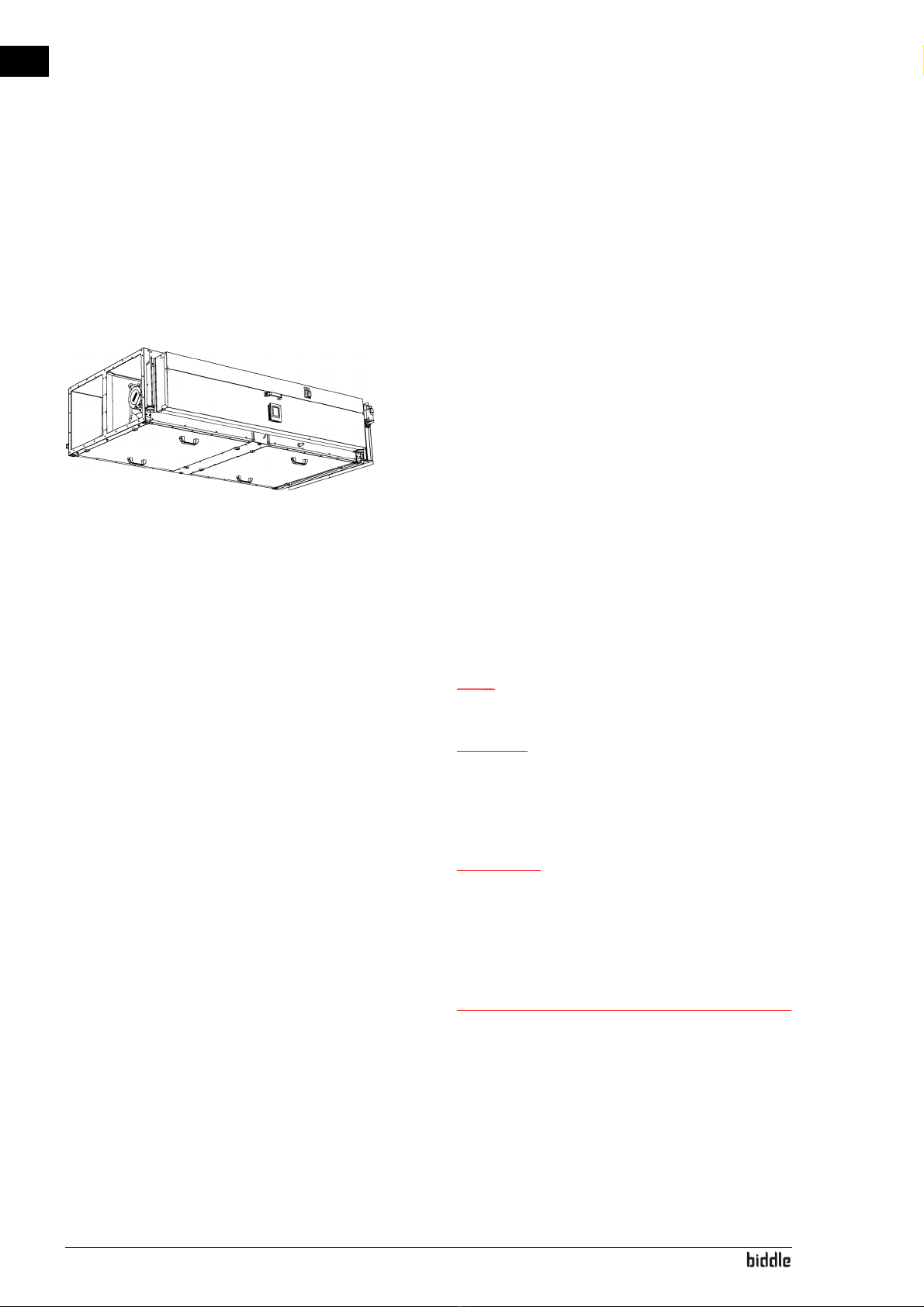
1.3 About the unit 5
1.4 Components and accessories 9
1.5 Safety instructions 10
2 Installation 11
2.1 Inspection on delivery 11
2.2 Hanging the unit up 11
2.3 Connecting the unit to the ventilation system 13
2.4 Installing condensate drain 14
2.5 Connecting the unit to Modbus 14
2.6 Installing the b-touch control panel (accessory) 16
2.7 Installing sensors for control (accessory) 17
2.8 Installing external controls 18
2.9 Connecting the unit to the mains supply 19
2.10 Switching on and checking operation 21
3Operationviab-touch 27
3.1 Control panel 27
3.2 The Home screen 28
3.3 Main menu 30
3.4 Preferences 31
3.5 Settings 32
3.6 Configuration 32
3.7 Maintenance 37
3.8 USB 39
4 Operation via Modbus 41
4.1 Frequently used register addresses 41
4.2 All register addresses 47
5Errors 48
5.1 Resolving simple problems 48
5.2 Remedying errors that are accompanied by an error message 49
5.3 Reading out errors 49
5.4 Error codes registers 49
5.5 Error messages on the control panel 50
5.6 Remedying errors that are not accompanied by an error message 50
HR 12 MANUAL
Manual version 1.0 (15-07-2018) en-3
en
6 Maintenance 52
6.1 Introduction 52
6.2 Replacing the filter 52
6.3 Cleaning the unit 53
6.4 Scheduled maintenance 53
7 Service 54
7.1 Cleaning the plate heat exchangers 54
7.2 Removing the control circuit board 56
7.3 Connecting the control circuit board 56
7.4 Fuses 57
7.5 Setting the unit code 57
7.6 Resetting the PIN code 58
7.7 Copying the settings 59
7.8 Updating the software 60
7.9 Composition of the Biddle control cable 62
8 Dismantling 63
9 Addresses 65
Keywords 66
en-4
en
1. . Introduction
1.1 About this manual
This manual describes the installation, operation and mainte-
nance of the heat-recovery unit HR. The manual also provides
instructions and information for servicing activities.
1.2 How to read this manual
1.2.1 Designations used in the manual
The following symbols are used in the manual:
Note:
nRefers to an important section in the text.
Caution:
cIf you do not carry out the procedure or action
correctly, you may cause damage to the unit.
Follow the instructions precisely.
Warning:
wIf you do not carry out the procedure or
action correctly, you may cause physical injury
and/or damage.
Follow the instructions precisely.
Danger:
dIs used to designate actions that are not
permitted.
Ignoring this prohibition may lead to serious
damage or to accidents resulting in physical
injury.
HR 12 MANUAL INTRODUCTION
Manual version 1.0 (15-07-2018) en-5
en
1.2.2 Symbols used on the unit and in the manual
The following symbols indicate possible risks or hazards. The
same symbols will also be found on the unit.
1.2.3 Related documentation
In addition to this manual, the following documentation is also
supplied with the unit:
• wiring diagram for installation and servicing.
1.3 About the unit
1.3.1 Application
The unit is designed to use heat recovery on ventilation air.
Other versions and intended use
Warning:
wApplications other than those described
above are deemed to be ‘usage other than for
the intended purpose’. Biddle is not liable for
damage or loss resulting from usage other
than for the intended purpose. Usage for the
intended purpose also entails observance of
the instructions in this manual.
SYMBOL DESCRIPTION
wYou have accessed a section of the unit containing components which carry
a voltage.
Access restricted to qualified maintenance staff only.
Caution is required.
wYou have accessed a section of the unit with running fans.
Caution is required.
INTRODUCTION HEAT RECOVERY UNIT
en-6
en
1.3.2 Type designation
In combination, the type designations constitute the type
code.
HR 12
1.3.3 Symbols on the unit
airflow
1.3.4 Type plate
The type plate is located on the side of the basicunit.
Designations on the type plate
TYPE CODE ELEMENT DESIGNATION MEANING
product series HR general designa-
tion for the series
capacity 12 1200 m3/h
AIRFLOW SYMBOL
supply air
extract air
exhaust air
fresh air
DESIGNATION MEANING
Type complete type code of the unit
Noserial number, production week and
year
Mweightofunit
Medium medium
HR 12 MANUAL INTRODUCTION
Manual version 1.0 (15-07-2018) en-7
en
1.3.5 Field of application
Observe the following limits for the unit:
Operating limits for all models
Warning:
wThe unit may not be used in potentially
explosive environments, outdoors or in very
dusty or aggressive air conditions.
Biddle shall not be held liable for damage caused by
use under these conditions.
Sound levels
Maximum sound power level in ducts
pmax maximum permissible operating pres-
sure
U power supply voltage
Imax max. current
Pmotor max. power consumption by fans
DESIGNATION MEANING
Ambient conditions Temperature 5 °C to 40°C
Relative air
humidity
20% - 95%, not
condensing
Power supply voltage see type plate
Power see type plate
SOUND POWER LEVEL
(LWRE. 10-12 W)
OCTAVE BAND CENTRE FREQUENCY (HZ)LWA
DB(A)
63 125 250 500 1000 2000 4000 8000
supply air 73.8 74.8 81.3 62.4 65.3 65.1 56.8 49.9 74.5
extract air 69.9 63.3 72.0 52.0 49.5 43.1 36.4 25.4 64.0
exhaust air 73.8 74.8 81.3 62.4 65.3 65.1 56.8 49.9 74.5
fresh air 69.9 63.3 72.0 52.0 49.5 43.1 36.4 25.4 64.0
INTRODUCTION HEAT RECOVERY UNIT
en-8
en
Maximum sound power level in unit housing
Maximum sound pressure level in standard room
Maximum number of units to be connected
The number of ventilation units that can be connected to the
heat recovery unit depends on the unit’s capacity and the
effective capacity of the ventilation units that are to be con-
nected.
If in doubt, consult your Biddle advisor.
See also:
1.3.4 "Type plate" on page 6
1.3.6 CE declaration
The unit is compliant with the applicable CE standards. The
complete CE Declaration of Conformity can be found at:
www.biddle.info.
1.3.7 Modifications and changes
Without the approval of Biddle, no changes or modifications
may be made to the unit that could adversely affect safety. The
CE declaration is no longer valid if the unit has been modified
or changed in any way.
TECHNICAL SPEED DB(A)
(LWA RE.10-12 W)
10 V DC (high speed) 61
8 V DC 59
6 V DC 55
5 V DC 49
TECHNICAL SPEED DB(A)
(LPA RE.2X10-5 N/M2)
10 V DC (high speed) 53
8 V DC 51
6 V DC 47
5 V DC 41
HR 12 MANUAL INTRODUCTION
Manual version 1.0 (15-07-2018) en-9
en
1.4 Components and accessories
1.4.1 Components supplied
Note:
nThe illustration shows the unit from above.
The unit consists of the following components:
• supply fan 1
• extract fan 2
•freshairfilter3
• extract air filter 4
• heat exchanger 5
• Electronics box 6
• Air dampers to fresh air7
• Pressure switch over the heat exchanger
• Pressure switch over the fresh air filter
1.4.2 Accessories
• Flexible manchets 0
• Pressure switch over extract air filter @
• Dirty filter warning lamp (during transport, this is stored in
the electronics module)
•b-touch operating panel with Biddle control cable
•Sensorforcontrol:
-CO
2sensor
•Smokedetector
1.4.3 Components not supplied
The following components required for installation must be
obtained from third parties:
• threaded rods M10
• mains power cable
• control cable to building management system
• drain pipe with trap for condensate drainage
INTRODUCTION HEAT RECOVERY UNIT
en-10
en
1.5 Safety instructions
1.5.1 Safety in use
Warning:
wDo not put any objects into the inlets and
outlets.
Warning:
wDo not obstruct the unit’s inlets or outlets.
Caution:
cIn exceptional situations, water may run out of the
unit. Therefore, do not place anything under the unit
that could be damaged as a result.
1.5.2 Safety issues relating to installation, mainte-
nance and servicing
Danger:
dThe unit may only be opened by qualified
technical staff.
Warning:
wPerform the following actions before opening
the unit:
1. Switch the unit off,.
2. Disconnect the mains supply (switch off the isolation
switch).
3. If you are going to carry out maintenance or repairs on
electrical components: switch the mains supply group off.