LG MULTIV III User manual

Heat Recovery Unit
SERVICE MANUAL
MODEL : PRHR041/PRHR041A
PRHR031/PRHR031A
PRHR021/PRHR021A
CAUTION
Before Servicing the unit, read the safety precautions in General SVC manual.
Only for authorized service personnel.
Internal Use Only
http://biz.lgservice.com
R410A

Air Conditioner Service Manual
TABLE OF CONTENTS
Safety Precautions .....................................................................................................3
Part 1 General Information ........................................................................................5
Model Names ...............................................................................................................................6
External Appearance ...................................................................................................................7
Nomenclature ...............................................................................................................................8
Part 2 HR Units ...........................................................................................................9
Part 3 PCB Setting....................................................................................................19
Part 4 Trouble shooting guide................................................................................ 35
Copyright ©2011 LG Electronics. Inc. All right reserved.
Only for training and service purposes LGE Internal Use Only
- 2 -

Safety Precautions
Safety Precautions
To prevent injury to the user or other people and property damage, the following instructions must
be followed.
■Incorrect operation due to ignoring instruction will cause harm or damage. The seriousness is
classified by the following indications.
■Meanings of symbols used in this manual are as shown below.
WARNING
CAUTION
This symbol indicates the possibility of death or serious injury.
This symbol indicates the possibility of injury or damage to properties only.
Be sure not to do.
Be sure to follow the instruction.
WARNING
■Installation
Copyright ©2011 LG Electronics. Inc. All right reserved.
Only for training and service purposes LGE Internal Use Only
- 3 -
When installing and moving the air conditioner to
another site, do not charge it with a different refrig-
erant from the refrigerant specified on the unit
• If a different refrigerant or air is mixed with the
original refrigerant, the refrigerant cycle may
malfunction and the unit
may be damaged.
R22
R407C
R410A
■Operation
Do not damage or use an unspecified power
cord.
• There is risk of fire, electric shock, explosion, or
injury.
Do not touch the power switch with wet
hands.
• There is risk of fire, electric shock, explosion, or
injury.
Safety Precautions
Copyright ©2011 LG Electronics. Inc. All right reserved.
Only for training and service purposes LGE Internal Use Only
- 4 -
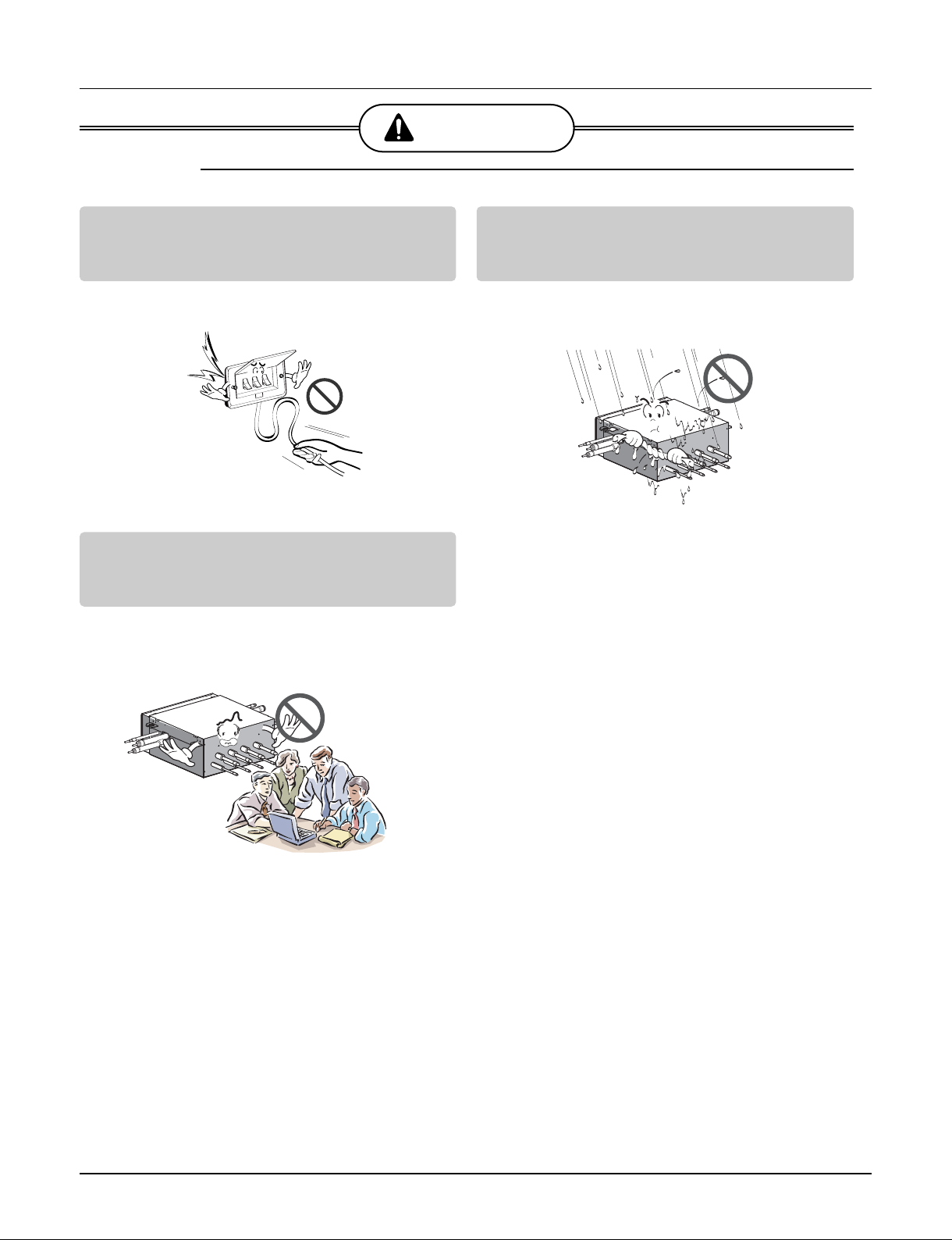
CAUTION
■Operation
Make the connections securely so that the
outside force of the cable may not be applied
to the terminals.
• Inadequate connection and fastening may gen-
erate heat and cause a fire.
Avoid a place where rain may enter since the
HR unit is for indoor
• There is risk of property damage, failure of prod-
uct or electric shock.
Install the HR unit at a place in which it is not
affected by operation mode changing noise.
• Installation within cell such as meeting room etc,
may disturb business due to noise.

- 5 -
Copyright ©2011 LG Electronics. Inc. All right reserved.
Only for training and service purposes LGE Internal Use Only
Part 1
General Information
1. Model Names ..................................................................6
2. External Appearance.......................................................7
3. Nomenclature...................................................................8

- 6 -
Copyright ©2011 LG Electronics. Inc. All right reserved.
Only for training and service purposes LGE Internal Use Only
Power Supply 2 branches 3 branches 4 branches
1Ø, 220-240V, 50Hz / 1Ø, 220V, 60Hz PRHR021 PRHR031 PRHR041
1Ø, 208/230V, 60Hz PRHR021A PRHR031A PRHR041A
1. Model Names
1.1 HR Unit
Model Names

- 7 -
Copyright ©2011 LG Electronics. Inc. All right reserved.
Only for training and service purposes LGE Internal Use Only
External Appearance
2. External Appearance
2.1 HR Unit
2 branches 4 branches
123
124
3 branches
123
PRHR021/PRHR021A PRHR031/PRHR031A PRHR041/PRHR041A

- 8 -
Copyright ©2011 LG Electronics. Inc. All right reserved.
Only for training and service purposes LGE Internal Use Only
Serial Number
No. of Connected branches
02 : For 2 branches
03 : For 3 branches
04 : For 4 branches
Indicates that this is System
HR Unit using the R410A
PRHR 04 1
Serial Number
No. of Connected branches
02 : For 2 branches
03 : For 3 branches
04 : For 4 branches
Indicates that this is System
HR Unit using the R410A
PRHR 04 1 A
Nomenclature
3. Nomenclature
3.1 HR Unit

- 9 -
Copyright ©2011 LG Electronics. Inc. All right reserved.
Only for training and service purposes LGE Internal Use Only
Part 2
HR Units

- 10 -
Copyright ©2011 LG Electronics. Inc. All right reserved.
Only for training and service purposes LGE Internal Use Only
1. Specifications ................................................................................................................11
2. Parts Functions .............................................................................................................12
3. Dimensions ....................................................................................................................13
4. Piping Diagrams ............................................................................................................14
5. Wiring Diagrams............................................................................................................15
6. Electric Characteristics ................................................................................................16
7. Functions .......................................................................................................................17
HR Units
This manual suits for next models
6
Table of contents
Other LG Heating System manuals


