Biddle HR 25 User manual

a
Manual
Heat recovery unit
Model HR 25/35/45
Version 3.0
Original Manual English

HEAT RECOVERY UNIT
en
en-2 B
. . . Contents
1 Introduction 4
1.1 About this manual 4
1.2 How to read this manual 4
1.3 About the unit 5
1.4 Components and accessories 11
1.5 Safety instructions 12
2 Installation 14
2.1 Inspection on delivery 14
2.2 Hanging the unit up 14
2.3 Connecting the unit to the ventilation system 17
2.4 Connecting the unit to the central heating and heat recovery system 18
2.5 Installing condensate drain 19
2.6 Connecting components to electronics module 20
2.7 Connecting the unit to the building management system 21
2.8 Installing the b-touch control panel (accessory) 21
2.9 Installing sensors for control (optional) 23
2.10 Installing external controls 23
2.11 Connecting the unit to the mains supply 25
2.12 Switching on and checking operation 27
3Operationviab-touch 32
3.1 Control panel 32
3.2 The Home screen 33
3.3 Main menu 35
3.4 Preferences 37
3.5 Settings 37
3.6 Configuration 38
3.7 Maintenance 41
3.8 USB 43
4 Operation of the building management system (BMS) 46
4.1 Frequently used register addresses 46
4.2 All register addresses 53
5Errors 54
5.1 Resolving simple problems 54
5.2 Remedying errors that are accompanied by an error message 55
5.3 Reading out errors 55
5.4 Error codes registers 55
5.5 Error messages on the control panel 56
5.6 Remedying errors that are not accompanied by an error message 56

HR MANUAL
Manual version 3.0 (10-10-2017) en-3
en
6 Maintenance 58
6.1 Introduction 58
6.2 Replacing or cleaning the filter 58
6.3 Cleaning the unit 59
6.4 Scheduled maintenance 59
7 Service 60
7.1 Cleaning the plate heat exchangers 60
7.2 Removing the control circuit board 62
7.3 Connecting the control circuit board 62
7.4 Fuses 63
7.5 Setting the unit code 63
7.6 Resetting the PIN code 64
7.7 Copying the settings 64
7.8 Updating the software 66
7.9 Composition of the Biddle control cable 67
8 Dismantling 68
9 Addresses 69
Keywords 70

en-4
en
1. . Introduction
1.1 About this manual
This manual describes the installation, operation and mainte-
nance of the heat-recovery unit HR. The manual also provides
instructions and information for servicing activities.
1.2 How to read this manual
1.2.1 Designations used in the manual
The following symbols are used in the manual:
Note:
nRefers to an important section in the text.
Caution:
cIf you do not carry out the procedure or action
correctly, you may cause damage to the unit.
Follow the instructions precisely.
Warning:
wIf you do not carry out the procedure or
action correctly, you may cause physical injury
and/or damage.
Follow the instructions precisely.
Danger:
dIs used to designate actions that are not
permitted.
Ignoring this prohibition may lead to serious
damage or to accidents resulting in physical
injury.

HR MANUAL INTRODUCTION
Manual version 3.0 (10-10-2017) en-5
en
1.2.2 Symbols used on the unit and in the manual
The following symbols indicate possible risks or hazards. The
same symbols will also be found on the unit.
1.2.3 Related documentation
In addition to this manual, the following documentation is also
supplied with the unit:
• wiring diagram for installation and servicing.
1.3 About the unit
1.3.1 Application
The unit is designed to use heat recovery on ventilation air,
with or without additional heating.
Other versions and intended use
Warning:
wApplications other than those described
above are deemed to be ‘usage other than for
the intended purpose’. Biddle is not liable for
damage or loss resulting from usage other
than for the intended purpose. Usage for the
intended purpose also entails observance of
the instructions in this manual.
SYMBOL DESCRIPTION
wYou have accessed a section of the unit containing components which carry
a voltage.
Access restricted to qualified maintenance staff only.
Caution is required.
wThis surface or component may be hot. Risk of burns on contact.
wYou have accessed a section of the unit containing rotating fans.
Caution is required.

INTRODUCTION HEAT RECOVERY UNIT
en-6
en
1.3.2 Type designation
In combination, the type designations constitute the type
code. For example: HR 35-HC6.
Explanation of the type code
1.3.3 Symbols on the unit
The modules are equipped with stickers and symbols. These
symbols provide information on:
• function
•airflow
components
T
YPE CODE ELE-
MENT DESIGNATION MEANING
product series HR general designa-
tion for the series
capacity 25 2500 m3/h
35 3500 m3/h
45 4500 m3/h
battery type A without heating
HC6 water heating,
cooling and/or
ventilation
accessory RM recirculation
module
FUNCTION SYMBOL
heat exchanger
recirculation damper
fan

HR MANUAL INTRODUCTION
Manual version 3.0 (10-10-2017) en-7
en
airflow
1.3.4 Type plate
The type plate is located on the side of the unit.
Designations on the type plate
filter
heating/cooling
AIRFLOW SYMBOL
supply air
extract air
exhaust air
fresh air
FUNCTION SYMBOL
DESIGNATION MEANING
Type complete type code of the unit
Noserial number, production week and
year
M weight of unit
Medium medium
pmax maximum permissible operating pres-
sure
U power supply voltage
Imax max. current
Pmotor max. power consumption by fans

INTRODUCTION HEAT RECOVERY UNIT
en-8
en
1.3.5 ERP product information
PRODUCT SERIES HR
Manufacturer Biddle bv
Type Non-residential ventilation unit/Bi-directional ventilation
unit (NRVU/BVU)
Drive Variable Speed Drive (VSD)
Heat Recovery System Regenerative Plate Heat Exchanger
TYPE HR25 HR35
Thermal efficiency of the heat recovery ηt,nrvu 78.8% 79.2%
Nominal flow rate (max.) qnom 0.69 m3/s 0.97 m3/s
Effective power consumption (max.) 1.56kW 2.64kW
Specific fan power (max.) SFPint 1214 W/m3/s 1389 W/m3/s
Filter area velocity (typical/max.) 1.9/2.6 m/s 1.5/2.4 m/s
Nominal external pressure (max.) Δps,ext 200 Pa 300 Pq
Internal pressure drop (ventilation) (max.) Δps,int 350 Pa 440 Pa
Internal pressure drop (additional) (max.) Δps,add 0 Pa 0 Pa
Static fan efficiency ηes 45.3% 53.3%
External leakage rate (max.) 0.23% 0.23%
Internal leakage rate (max.) 0.09% 0.09%
Filter energy performance (typical/max.) 273/1355 kWh/
year
779/1906 kWh/
year
Sound level housing (typical/max.) Lwa 63/74 dB(A) 55/66 dB(A)
GENERAL INFORMATION
Visual filter warning error message on b-touch control panel,warning lamp (acces-
sory), BMS alarm
Regularly replace the filters for optimum perfor-
mance and energy efficiency of the unit
Dismantling instructions see 8 Dismantling

HR MANUAL INTRODUCTION
Manual version 3.0 (10-10-2017) en-9
en
1.3.6 Field of application
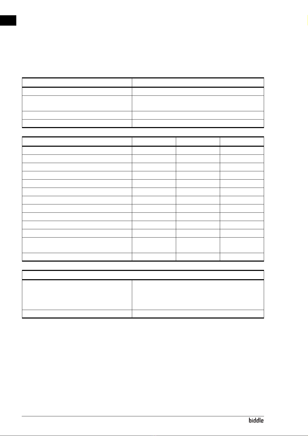
Observe the following limits for the unit:
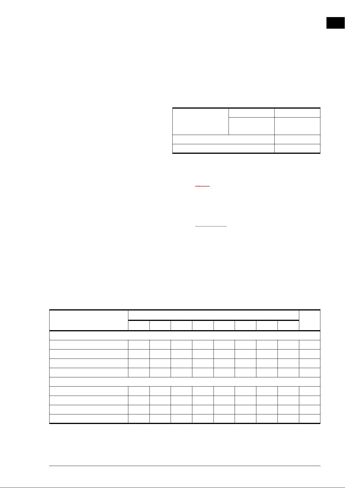
Operating limits for all models
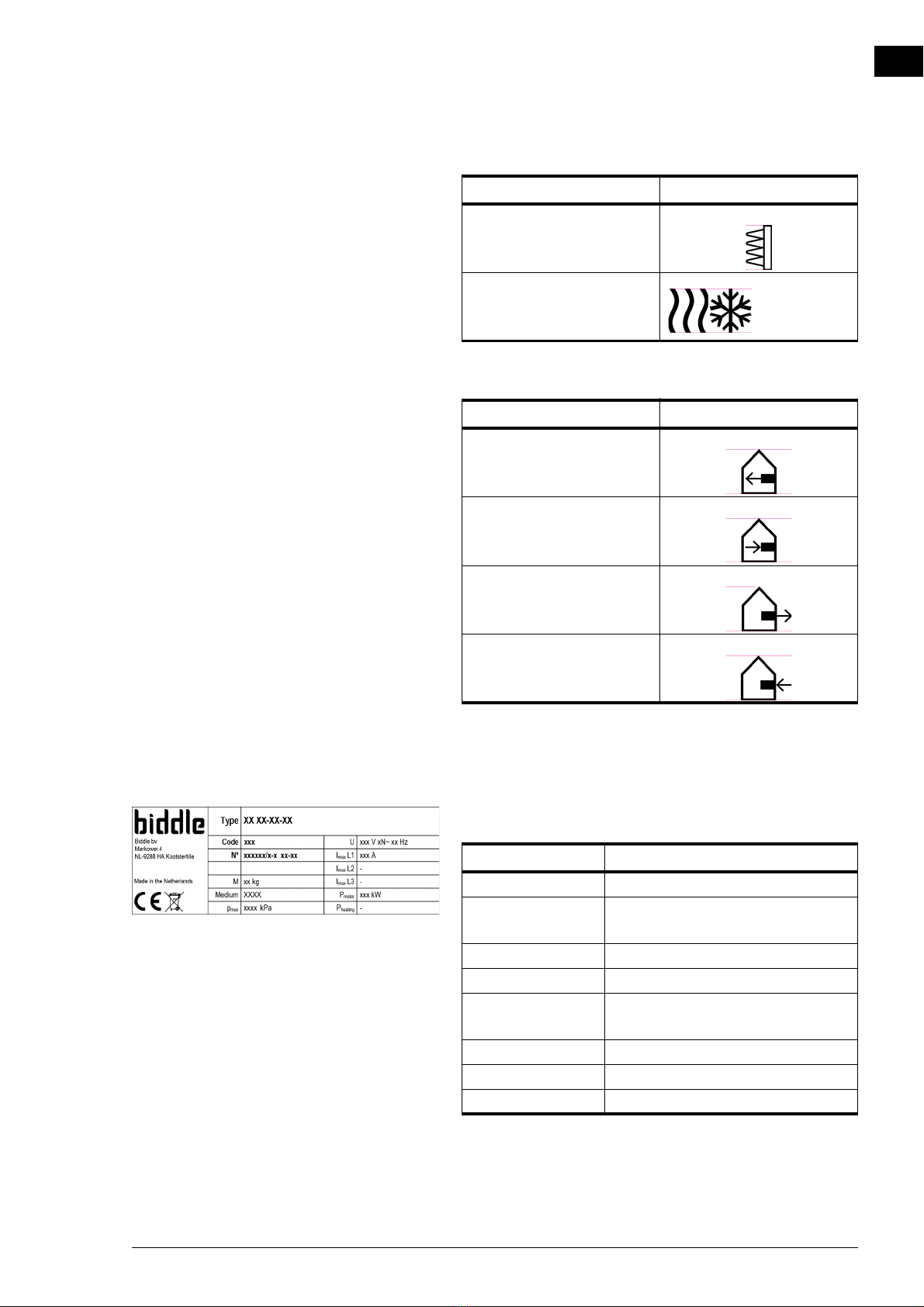
Parameters of use for water-heated models
Note:
nConsult Biddle if you want to connect a unit to a
water flow-path with higher temperatures and higher
pressure.
Warning:
wThe unit may not be used in potentially
explosive environments, outdoors or in very
dusty or aggressive air conditions.
Biddle shall not be held liable for damage caused by
use under these conditions.
Sound levels
Maximum sound power level in ducts
Ambient conditions Temperature 5 °C to 40°C
Relative air
humidity
20% - 95%, not
condensing
Power supply voltage see type plate
Power see type plate
SOUND POWER LEVEL
(LWRE. 10-12 W)
OCTAVE BAND CENTRE FREQUENCY (HZ)LWA
DB(A)
63 125 250 500 1000 2000 4000 8000
HR 25
supply air 69.8 65.6 76.4 75.1 78.8 80.4 78.5 74.1 85.5
extract air 65.7 60.5 70.6 69.9 67.4 70.8 70.9 66.7 76.6
exhaust air 69.8 65.6 76.4 75.1 78.8 80.4 78.5 74.1 85.5
fresh air 65.7 60.5 70.6 69.9 67.4 70.8 70.9 66.7 76.6
HR 35
supply air 75.8 70.7 78.6 78.4 81.3 81.2 78.3 75.4 86.6
extract air 68.6 65.8 75.5 72.3 69.2 70.2 68.2 67.2 76.7
exhaust air 75.8 70.7 78.6 78.4 81.3 81.2 78.3 75.4 86.6
fresh air 68.6 65.8 75.5 72.3 69.2 70.2 68.2 67.2 76.7

INTRODUCTION HEAT RECOVERY UNIT
en-10
en
Maximum sound power level in unit housing
Maximum sound pressure level in standard room
Maximum number of units to be connected
The number of ventilation units that can be connected to the
heat recovery unit depends on the unit’s capacity and the
effective capacity of the ventilation units that are to be con-
nected.
If in doubt, consult your Biddle advisor.
See also:
1.3.4 "Type plate" on page 7
1.3.7 CE declaration
The unit is compliant with the applicable CE standards. The
complete CE Declaration of Conformity can be found at:
www.biddle.info.
1.3.8 Modifications and changes
Without the approval of Biddle, no changes or modifications
may be made to the unit that could adversely affect safety. The
CE declaration is no longer valid if the unit has been modified
or changed in any way.
TECHNICAL SPEED
DB(A)
(LWA RE.10-12 W)
HR 25 HR 35
10 V DC (high speed) 74 74
8 V DC 68 69
6 V DC 63 64
5 V DC 58 60
TECHNICAL SPEED
DB(A)
(LPA RE.2X10-5 N/M2)
HR 25 HR 35
10 V DC (high speed) 66 66
8 V DC 60 61
6 V DC 55 56
5 V DC 50 52

HR MANUAL INTRODUCTION
Manual version 3.0 (10-10-2017) en-11
en
1.4 Components and accessories
1.4.1 Components supplied
Note:
nThe illustration shows the unit from above, whereby
the air exchange with the interior takes place on the
left side and the air exchange with the exterior takes
place on the right side.
• Modules:
- supply fan 1
- extract air filter 2
- extract fan 3
-freshairfilter4
-recirculationdamper5
- heat exchanger 6
- heating/cooling element 7(depending on the type of
unit)
• Electronics module 8
• Fastening material for linking the modules to each other.
1.4.2 Accessories
• Flexible cuffs (attached to modules) 0
• Air dampers to fresh air (attached to modules) !
• Pressure switch over filters (attached to modules) @
• Dirty filter warning lamp (during transport, this is stored in
the electronics module)
•b-touch control panel
• Sensor for control:
-CO
2sensor
1.4.3 Components not supplied
The following components required for installation must be
obtained from third parties:
• threaded rods (M10)
• mains power cable
• control cable to building management system
• drain pipe with trap for condensate drainage

INTRODUCTION HEAT RECOVERY UNIT
en-12
en
1.5 Safety instructions
1.5.1 Safety in use
Warning:
wDo not put any objects into the inlets and
outlets.
Warning:
wDo not obstruct the unit’s inlets or outlets.
Warning:
wThe upper surface of the unit becomes hot
during operation.
Caution:
cIn exceptional situations, water may run out of the
unit. Therefore, do not place anything under the unit
that could be damaged as a result.
1.5.2 Safety issues relating to installation, mainte-
nance and servicing
Danger:
dThe unit may only be opened by qualified
technical staff.
Warning:
wPerform the following actions before opening
the unit:
1. Switch the unit off,.
2. Allow the unit to cool down.
Caution:
cThe heat exchanger or, as the case may be, the
heating elements, can get very hot.

HR MANUAL INTRODUCTION
Manual version 3.0 (10-10-2017) en-13
en
3. Disconnect the mains supply (switch off the isolation
switch).
4. If you are going to carry out maintenance or repairs on
electrical components: switch the mains supply group off.
5. For water-heated models:
shut off the central heating feed (if possible).
Warning:
wThe fins of the heat exchanger are sharp.

en-14
en
2. . Installation
Warning:
wInstallation activities may only be performed
by technical staff qualified for this purpose.
Warning:
wBefore starting installation: read the safety
instructions.
See also:
1.5 "Safety instructions" on page 12
2.1 Inspection on delivery
• Check the unit and the packaging to ensure that they have
been delivered in good order. Notify the driver and the
supplier immediately if any shipping damage is detected.
• Ensure that all components are present. Notify supplier of
any missing parts immediately.
See also:
1.4 "Components and accessories" on page 11
2.2 Hanging the unit up
2.2.1 Determining the location of the unit
• Make sure that the structure from which the unit is about
to be suspended can bear at least 4 times the weight of the
unit. The unit’s weight is indicated on its type plate.
• The distance between the floor and the unit’s underside
must be more than 2.7 m.
• Make sure that the electronics and the pressure meters on
the unit’s long side remain easily accessible.
• Keep the underside of the unit accessible on account of
the inspection hatches.

HR MANUAL INSTALLATION
Manual version 3.0 (10-10-2017) en-15
en
• In exceptional situations, water may run out of the unit.
Make sure that this cannot cause any damage or danger-
ous situations.
•For models with heating: The distance between the ceiling
and the top of the unit must be more than 25 mm.
See also:
1.3.4 "Type plate" on page 7
2.2.2 Hanging the unit up
This manual explains how to suspend the unit for each mod-
ule. Depending on the situation, a different sequence of sus-
pending the units may be selected.
Consult the overview sticker for the module positions in the
specific composition of your unit.
Fixing the threaded rods
Fix threaded rods M10 in accordance with the dimensions in
the table. Make sure the threaded rods are perpendicular.
Note:
nOnly fix the threaded rods for the modules in the
specific composition of your unit. See the overview
sticker.
Note:
nThe illustration shows the unit from above, whereby
the air exchange with the interior takes place on the
left side and the air exchange with the exterior takes
place on the right side.
Note:
nThe threaded rods must be secured, otherwise the
unit may fall down.
SIZE TYPE DIMENSIONS
A HR 25 1558 mm
HR 35 2158 mm
HR 45 2758 mm
B all models 1450 mm
C all models 450 mm
x all models 54 mm

INSTALLATION HEAT RECOVERY UNIT
en-16
en
Hanging the unit up
1. Mount the electronics module on the side of the heat
exchanger module .
2. Move the heat exchanger module into position.
3. Attach the module to the threaded rods with nuts 1.
Note:
nMake sure the rubbers and rings 2for damping stay
in the right place.
Caution:
cMake sure that the module is hanging level in both
directions.
4. To each threaded rod, apply a lock nut 3.
5. Move the recirculation damper module into position.
6. Attach the module in the same way as the heat exchanger
module (steps 2 and 3).
7. Connect the modules to each other with the coupling ele-
ments at top and bottom.
Caution:
cAdjust the modules individually before they are
connected to each other.

HR MANUAL INSTALLATION
Manual version 3.0 (10-10-2017) en-17
en
8. Connect the supply fan module and the extract air fil-
ter module M5 to each other with the coupling ele-
ments at top and bottom.
9. Connect the extract fan module and the fresh air fil-
ter module F7 to each other with the coupling ele-
ments at top and bottom.
10. Repeat steps 4 to 6 for both linked assemblies.
11. Bring the heating module (if available) into position.
12. Repeat steps 5 and 6 for the heating module.
Securing the unit
1. Secure the suspension to the threaded rods by tightening
all lock nuts 3.
Warning:
wThe threaded rods must be secured,
otherwise the unit may fall down.
2.3 Connecting the unit to the ventilation system
Using channel sections, connect the unit to the fresh air, the
inside air and to the ventilation units.
Note:
nTake into account any sensors for the controls which
have to be placed in the ducts.
See 2.9 Installing sensors for control (optional)
When opting for the duct cross-section, take into account:
• The maximum allowable pressure difference for the
required capacity. (see diagram under 2.12.4> Setting the
fan speeds)

INSTALLATION HEAT RECOVERY UNIT
en-18
en
• The desired maximum air velocity.
Note:
nIf the duct cross-section is too small, this may lead
to reduced capacity and/or noise nuisance.
Note:
nIn order to prevent condensation, Biddle
recommends insulating the channel sections between
the HR unit and the fresh air.
See also:
2.12 "Switching on and checking operation" on page 27
2.4 Connecting the unit to the central heating and heat recovery sys-
tem
2.4.1 Connecting the water-side control (accessory)
Only for models with water heating/cooling module:
The heating/cooling module can be fitted with a water-side
control to control the temperature of the water battery.
Caution:
cBiddle supplies suitable 2-way and 3-way valves as
accessories.
1. Connect the control valve and the drive to the heat
exchanger, in accordance with the diagram. In doing so, fol-
low the instructions given in the control valve manual.
Note:
nEnsure that the axis of the valve is in the correct
position when connecting the drive. See the control
valve manual.

HR MANUAL INSTALLATION
Manual version 3.0 (10-10-2017) en-19
en
2. Connect the drive to the valve in accordance with the wir-
ing diagram.
Caution:
cConnect the drive to the building management
system or another control system.
2.4.2 Connecting the unit
1. Connect the unit to the central heating system.
2. Vent the heat exchangers.
3. Check the connections for leakage.
2.5 Installing condensate drain
The cooling of the air can cause condensation. The unit is fit-
ted with one or more drain trays to catch condensation water.
1. Connect one of the connection points 1(15 mm) of the
heat exchanger module to a drainage system.
Caution:
cOn models that are used for cooling, also connect
the connection point of the cooling module 2(15
mm) to a drainage system.
WIRING DIAGRAM 2-WAY VALVE WIRING DIAGRAM 3-WAY VALVE

INSTALLATION HEAT RECOVERY UNIT
en-20
en
Pay attention to the following installation criteria:
- Make sure the drainage pipe has a drop of at least 1 in
50.
- Fit the drainage pipe with a trap with dimensions as
shown in the illustration. Fill this with water before the
unit is used for the first time.
Caution:
cThe trap must always be filled with water.
2. Cap off other connection points.
Caution:
cIf the connection points are not shut off, water may
run out of the unit.
2.6 Connecting components to electronics module
1. Connect the various unit components to the electronics
module in accordance with the wiring diagram:
Note:
nSome components are optional (accessories).
- supply fan module :
- power supply: X1 1(via cable gland in box)
- control system + input valve: 2
- extract fan module :
- power supply: X1 3(via cable gland in box)
- control system: 4
- recirculation damper module : 5
-heatexchangermodule :
- by-pass damper: 6
- pressure difference meter: 7
-temperature sensors: 8
- fresh air filter module : 9
See also:
1.3.3 "Symbols on the unit" on page 6
Other manuals for HR 25
1
This manual suits for next models
2
Table of contents
Other Biddle Heating System manuals
Popular Heating System manuals by other brands

Danfoss
Danfoss Link HR installation manual

SND
SND SND-6-ECO owner's manual

Viessmann
Viessmann Vitodens 100-W operating instructions

Current Tools
Current Tools 441 Operating and safety manual

aerauliqa
aerauliqa QR100M Installation, use and maintenance manual

Yellow Diving
Yellow Diving THERMOV Manual And Maintenance Directions

Nibe
Nibe SCA 35 Installer manual

Cetetherm
Cetetherm Midi Wall TA Installation, service and operating instruction

Kampmann
Kampmann Katherm NX installation instructions

Reznor
Reznor RDF 1-20-3 manual

WATERKOTTE
WATERKOTTE EcoTouch Ai1 Geo Planning and installation

Viessmann
Viessmann VITODENS operating instructions