Biegler BW 585 User manual

November, 2007 BW Manufacture, Assembly, Test Documentation
Biegler
Blood and Infusion Warmer
Manufacture, Assembly and
Test Documentation
BW 585
PCB Version BW 585 V1.6
Software V 1.2

Page 2 BW Manufacture, Assembly, Test Documentation November, 2007
Contents
1. TechnicalData 3
2. NotesfortheUser 4
3. SafetyCut-off 5
4. Temperature Adjustment 7
5. Assembly and Dismantling 10
6. Inspection Instructions 13
7. Test Records for BW 585 19
8. SafetyChecks 20
9. ElectricalSafety 22
10. PartsLists 24
11. Exploded Drawing and
Component Mounting Diagrams

November, 2007 BW Manufacture, Assembly, Test Documentation Page 3
Technical Data - BW 585
Model BW 585
Voltage 230 VAC / 110 VAC
Frequency 50 Hz
Power consumption 300 W
Preheating time max. 60 sec
Operating temp. 37 - 41°C
Safety cut-off three-fold
Moisture resistance IPX4
Protection class I
Protection grade B
Dimensions 140 x 190 x 230 mm
Weight 2,0 kg
Fuses 230VAC 1,6A slow (primary)
0,315A slow (secondary)
110 VAC 3,15A slow (primary)
0,315A slow (secondary)
1. Technical Data

Page 4 BW Manufacture, Assembly, Test Documentation November, 2007
Manufacturer’s Responsibility
Biegler or the Company’s authorised dealers shall only be responsible for the equipment’s
safety, reliability and performance if:
•the operating instructions are adhered to during use
•the electrical installations in the room where the equipment is used meet the statutory
technical requirements
•modifications, repairs or adjustments are or were carried out solely by Biegler or
authorised personnel
•only original Biegler spare parts are used for repairs (also applies to power supply cable).
If the buzzer or red warning light comes on, remove the infusion or transfusion tube from the
heating element and disconnect the connection tube to the patient immediately .
WARRANTY
Biegler Medizinelektronik guarantees this device against material and manufacturing defects
for a period of twelve months from the date of purchase. The warranty also covers spare
parts and workmanship. All claims must be accompanied by an invoice or proof of purchase
and submitted within the warranty period. The warranty does not apply if the device has
suffered damage, been tampered with, misused or not maintained in accordance with the
operating instructions.
2. Notes for the User

November, 2007 BW Manufacture, Assembly, Test Documentation Page 5
42°C ( Software )
•switch on the warmer
•preheat the device to 41°C and wait for the temperature to stabilize
•remove the mains plug
•hold down the ↑control and reconnect the mains power plug
•push the On/Standby switch (BW heats up to a target temperature of 42,5°C)
•once it has cooled down, the equipment is ready for restart again
•Observe the temperature indicator carefully; the high temperature alarm should be
triggered at a temperature of 42°C. For reasons of safety, short beeping sounds are
given at intervals of a second in this operational mode and the Led ON indicators
flash alternately
42,5°C ( Hardware )
•switch on the warmer
•preheat the device to 41°C and wait for the temperature to stabilize
•press the “e” key on the computer. Now the device is in the service-mode (the LED`s
ON and STANDBY flash alternately)
•the device now heats up to a target temperature of 42,5°C
•wait for the temperature to stabilize
•turn the spindle-trimmer P5 slowly clockwise, until the alarm-buzzer gets active
•now the BW 585 slowly cools down
Now check the safety cut-off again !
45°C ( thermal time delay )
•if there is a problem with the first and the second safety cut-off, the heating circuit is
opened by a thermal time delay
•once it has cooled down, the safety cut-off of the soft- and hardware must be tested
•if these tests have a positive result, the equipment is ready for operation again
•this safety cut-off sequence could also be activated, if the blood-warmer is placed too
near a heating source or is exposed to direct sun-radiation
3. Safety Cut-off

Page 6 BW Manufacture, Assembly, Test Documentation November, 2007
37°C ( low temperature alarm )
•The low temperature alarm could only be activated 60 seconds after switch on the
warmer. If the temperature of the heat-exchanger drops below 36,5°C, the low
temperature alarm will be activeted , the first LED of the temperature control will
flash and an intermittent audio alarm will sound. The heating circuit will not shut off
.If the temperature increases to 37°C, the both alarms will stop
Difference-alarm
•if the difference of the values of the two temperature channels is >1,5°C, the
electronic cut-off triggered by the software activates both alarms, it is shown on the
display and the heating circuit shuts off.
The 3. LED for channel 1 and the 4.LED for channel 2.
IMPORTANT: if there is any fault in the safety cut-off circuits, the blood-
warmer must be checked by a local authorized service
organisation !
3. Safety Cut-off

November, 2007 BW Manufacture, Assembly, Test Documentation Page 7
1) Preparing to set the temperature
•Start the test program on the computer
•Plug the PC – BW 585 connecting cable into the test socket with the flat side facing
outwards
•Connect the blood warmer to the power supply
•Now the BW is in stand-by mode (the stand-by LED is illuminated and the operating
state displayed on the monitor)
•Turn trimmer P5 to the left as far as it will go
•Press the “T” key on the computer to start the test-mode
2) Setting the controller and monitoring
•Switch on the blood warmer ( press ON - the green LED indicates ON)
•Trimmers P3 – control (“t reg” on the monitor) and P6 – monitoring (“UW” on the
monitor) have to be set to the same values.
•Adjust P3 and P6 until the temperature on the heat exchanger is 38.5 °C and the
reading for “t reg” and “UW” is 38.5
•The temperature displayed on the device must also be 38.5°C.
3) Checking the settings at maximum temperature (41°C)
•Press ↑to set the temperature to 41°C in stand-by mode
•After heating up briefly, the temperature on the heat exchanger should be 41 ±0.3°C.
The readings for t reg and UW should both be 41 ±0.1°C.
•The temperature displayed on the device must also be 41°C
IMPORTANT: if the difference is outside the tolerance, repeat the adjustment procedure
from Section 2
4) Setting the safety cut-off at 42,5°C (Hardware)
•Switch on the blood warmer and preset it to 41°C
•Wait for the BW to heat up (approx. 1 minute)
•Press the “e” key on the computer
The blood warmer is now in set mode which is indicated by the two LEDs flashing
(stand-by and ON).The device will now heat up to 42.5°C.
Wait for the temperature to stabilise (approx. 1 minute)
•Turn trimmer P5 slowly to the right until the alarm buzzer is activated
•Let the blood warmer cool down
•Heat up the device again (start by pressing “e”) and check the safety cut-off setting
again
4. Temperature Adjustment
Page 8 BW Manufacture, Assembly, Test Documentation November, 2007
5) Checking the safety cut-off at 42°C (Software)
•switch on the warmer
•preheat the device to 41°C and wait for the temperature to stabilize
•remove the mains plug
•hold down the ↑control and reconnect the mains power plug
•push the On/Standby switch (the device now heats up to a target
temperature of 42,5 °C)
•once it has cooled down, the equipment is ready for restart again
•Observe the temperature indicator carefully; the high temperature alarm should be
triggered at a temperature of 42°C. For reasons of safety, short beeping sounds are
given at intervals of a second in this operational mode and the Led ON indicators
flash alternately
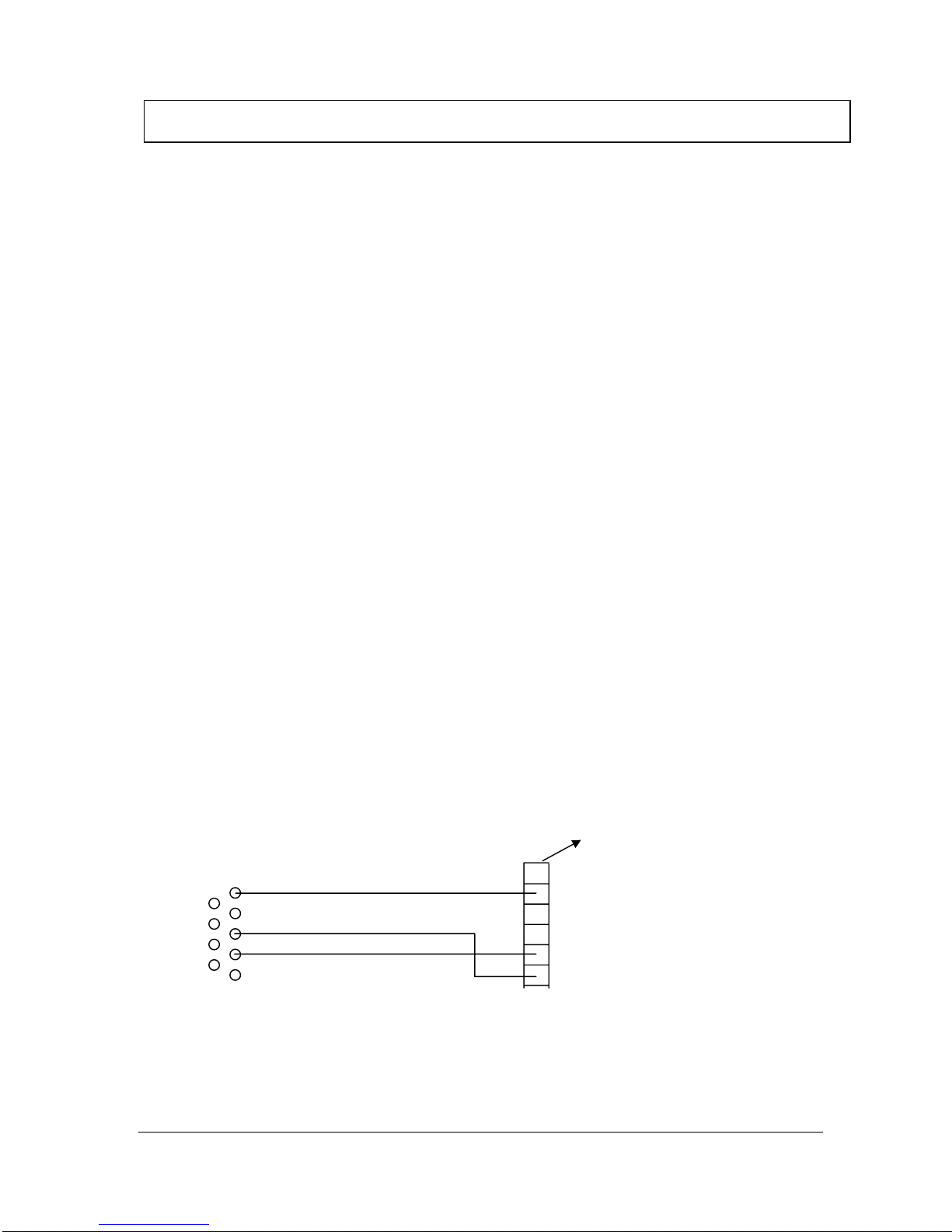
Service interface
The BW 585 is equipped with a service interface. The serial interface supplies a range of data
which can prove very useful when calibrating and troubleshooting. The BW 585 can be
connected direct to a PC or terminal with a suitable cable (see below) and the data displayed
using a standard terminal program (Hyper Terminal).
Data format:
19,200, n, 8, 1
PC power lead
CON 8 test plug
1
PC 9-pin SUB-D F
GND
TXD
RXD
Hyper terminal settings:
19,200, 8, n, 1
NOTE: all input in “LOWER CASE”
4. Temperature Adjustment

November, 2007 BW Manufacture, Assembly, Test Documentation Page 9
Input
Orders: “s” Standby
“r” Run
“t” Test mode (alarm off)
“e” Set mode (42.5°C, internal alarm not activated)
“n” Normal mode
Readings displayed
Protocol: “t soll” Set temperature
“t reg” Sensor 1 control temperature
“UW” Sensor 2 monitoring temperature
“t mean” Mean temperature
“S/I” Difference between set and actual
“max Dif” Difference between Sensor 1 and Sensor 2
“P%” Heating power in % (Maximum: 280 W)
“err” Error counter
“t” Time window for undertemperature alarm
“s” Heating rate
Error codes:
The BW585 differentiates between various errors and display them on the bar graph
■ Low temperature alarm (1st LED flashes)
■■Temperature difference between Sens1 and Sens2>1,5 °C
■■Sens1>42°C
■■Sens2>42°C
4. Temperature Adjustment

Page 10 BW Manufacture, Assembly, Test Documentation November, 2007
1. Work procedure
1. Check that the ring has no burrs or stains.
2. Screw four M4 x 5 mm threaded pins into the rear face of the ring. Ensure that the pins are
screwed in far enough to be flush with the ring face and secure them with Loctite 222
3. Apply a small drop of Wacker A07 translucent silicone to the O-ring groove on the front of
the ring at 30-40mm intervals
4. Starting from the locking element, insert the O-ring cord right round the groove, cut to
length, check that it is properly in place, press in firmly and leave to harden.
5. Remove any grease from the inside of the ring using alcohol.
6. Remove the backing from the strip heater.
7. Insert the strip heater from the back of the ring and apply, working counterclockwise,
bearing in mind the next step (8).
8. Centre the round bimetallic plate cut-out in the strip heater between the two notches for the
retaining spring in the aluminium ring and ensure that there is no gap between the strip
heater and the collar at the front of the ring.
9. Press the strip heater firmly onto the ring using a roller (note: there should be no air
pockets between the heater and the ring)
10.Seal the strip heater joint with General Electric RTV 116 Q RED DE 003 silicone in the
shape of an H.
11.Clean out the sensor bores on the ring collar (using 2.1mm dia. drill) and blow out.
12.Screw the sensor pcb, with conductor side facing outwards, from the inside onto the collar
using a M2,5 x 4 mm cheese head screw, 2,6mm dia. toothed lock washer and short
earthing wire.
13.Cover the sensor connections of the two temperature sensors with 0.6 x 12.5 mm dia.
sleeving.
14.Apply a thin coat of thermo-lubricant to the sensor housing and insert the housing as far as
it will go into the two cleaned bores beside the sensor pcb. IMPORTANT: the
sleevings must also be touching the sensor housing- adjust, if necessary. The sensor
connection poles can be reversed (the temperature sensor is a resistance sensor).
15.Bend the connections down to the sensor pcb, hold in place with a suitable tool and solder.
16.Glue the application needle onto the Luer cone of the 2 ml syringe with cyanoacrylate
adhesive. Fill the syringe half full with Wacker A07 translucent silicone.
17.Insert the needle into the sensor hole up to sensor housing and fill the bore, starting from
the bottom.Silicone should ooze out between the sleeving and the sensor connection.
18.Seal the soldered connections on the sensor pcb with the same silicone.
19.Glue the red plastic part into the sensor bore cutout using cyanoacrylate adhesive and press
flat.
20.Remove the bimetallic plate mounting flange.
21.Insert the bimetallic plate on the underside of the retaining spring. NOTE:ensure that
the retaining spring is in the position shown in the drawing!
22.Glue tapered washer in position facing bimetallic plate connections using Loctite LT 480.
23.Press retaining spring into locator on ring. Retaining spring must be fully lodged in the two
notches.
24.Ensure curved contour of tapered washer is seated properly in the ring radius by turning
bimetallic plate.
25.Once aligned, glue the bimetallic plate in place with Loctite LT480 between washer and
ring.
5. Assembly and Dismantling

November, 2007 BW Manufacture, Assembly, Test Documentation Page 11
26.Screw earthing wire with 3.0 mm dia. ring eye to inside of collar at back of ring and at the
same height as the sealed strip heater joint using M2.5 x 4 mm cheese head screw and 2.6
mm dia. toothed lock washer.
27.Contact assignment of 8-pin socket housing, starting with marking1
•Marking 1 Strip heater 230V: 1 x red 110V: 2 x
red
•No.2 Strip heater 230V: 1 x red 110V: 1 x
white
•No.3 Not assigned
•No.4 Bimetallic plate
•No.5 Bimetallic plate
•No.6 1 st. outer wire - sensor pcb (+)
•No.7 Middle wire - sensor pcb (earth)
•No.8 2 nd. Outer wire - sensor pcb (+)
2. Pre-head work procedure
•Check visually that the pre-head is free of burrs, defects in finish and soiling
•Screw two M5x25 grub screws into the inserts
•Screw the studs onto the M5x25 grub screws in the pre-head. Remove the insulating
cover and tighten the studs with a tool
•Replace the previously removed insulating covers
•Push the earthing jumper onto the studs
•Bend the display LEDs on the board to the front, connect the keypad PCB to the main
PCB, push from the LED side into the back of the pre-head and attach to the pre-head
with 2 special screws
•Ensure that the earthing jumper is parallel to the PCB that has been pushed forward as far
as it will go
•The distances between the LEDs have to be the same
•The LEDs have to be flush with the bottom of the film at a distance of +0/-0.2 mm
•Attach the earthing jumper to the stud with an M3x6 cheese head screw and lock with
capillary 222
•Attach the main PCB to the grounding bar with an M3x6 cheese head screw
•Check the front film visually
•Remove the protective film and apply to the front of the pre-head
•Screw the pre-assembled grounding cable to the earthing jumper with an M4x6 cheese
head screw + toothed lock washer (insert toothed lock washer between screw head and
eye)
•Apply the grounding sticker the earthing jumper besithe grounding cable
5. Assembly and Dismantling

Page 12 BW Manufacture, Assembly, Test Documentation November, 2007
3. Rear panel work procedure
•Screw an M4x30 headless setscrew into the bore bottom left in the clip as an earthing
screw
•Place the plate on the clip and screw together as described below
•Screw M4x12 with washer into the two bores on the top
•Insert an M4x10 countersunk head screw into the lower bore
•Lock the earthing setscrew with a nut and washer
•Fix the terminal in place with a 2.9x16 countersunk head Parker screw
•Apply the earthing stickers to the right and left of the lower connection on the terminal
•Thread the mains cable with cord grip in from the rear, bolt with the nut and lock with
Loctite 406
•Connect the three leads to the block terminal as follows:
Blue lead centre
Brown lead top
Yellow/green lead bottom
•Screw the l=65mm grounding cable onto the second side of the lower connection and
thread the other end including the toothed lock washer onto the earthing screw
•Thread the l=75mm grounding cable including the toothed lock washer onto the earthing
screw and screw the other end together with the mains filter onto the rear panel as follows:
Mains filter / toothed lock washer / cable / toothed lock washer / nut →fix in place
with a M4x20 headless setscrew.
4. Final assembly work procedure
•Ring: pull the cable connectors (except grounding cable) out at the side of the O-ring.
Insert the pre-head from this side and plug into the 8-pin connector
•Thread the pre-head and ring grounding cables through the neck and attach to the earthing
screw on the rear panel with toothed lock washers
•Connect the mains filter cable to the board
•Assemble all four parts (pre-head, ring, neck and rear panel). Make sure that the locking
pin is in the correct position in the ring with reference to the pre-head and the milling on
the neck is facing the rear panel
•Ensure that the leads are laid correctly so that once the device has been assembled no
leads can get caught between the two assembly bars and the rear panel
•Secure the assembled parts with two M4x16 cheese head screws and two 4.2 mm washers
in the back of the rear panel
5. Assembly and Dismantling

November, 2007 BW Manufacture, Assembly, Test Documentation Page 13
Inspection
Instructions
BW 585
Blood Warmer

Page 14 BW Manufacture, Assembly, Test Documentation November, 2007
BW 585 Inspection
The person carrying out inspection of the equipment must be familiar
with all the steps described in these instructions.
The instructions are intended as a reference for completing the BW 585
inspection records.
BIEGLER will notify customers of any amendments.
All supplements must be added to the reference documentation.

November, 2007 BW Manufacture, Assembly, Test Documentation Page 15
1. CONTINUOUS TEST
1.1 General
•Start-up at 38,5 °C
•After approx. 15 min. measure the temperature at the heat exchanger
•After 24 h measure the temperature again
During this test the initial and final values must be within the tolerance range and
the measurements must be taken under the same ambient conditions.
The final temperature may deviate from the initial value by ±0.5°C.
Measuring instrument used: TESTO infrared thermometer QUICKTEMP 860-T2
Accuracy: ±1%of reading or ±1°C
Emission: 0,98
1IR thermometer
2 Heat exchanger
(BW ring)
Fig. 1.1.1Measurement set-up
12
60 +/- 10 mm

Page 16 BW Manufacture, Assembly, Test Documentation November, 2007
2.READY FOR USE
2.1 General
•Start-up at 41 °C
•Time how long it takes for the operating temperature of 40,5°C to be
reached
The initial temperature should be the same as the ambient temperature.
The time taken must be less than 60 sec.
For arrangement of heat exchanger and measuring instrument, see Fig.1.1.1
3.OPERATING TEMPERATURE CHECK
3.1 General
The following checks must not be performed until the equipment has heated up
(control circuits in steady state).
The preliminary election of the temperature is 41 °C.
The heat exchanger temperature should be 41 ±0.5°C with the display reading
41°C.
For arrangement of heat exchanger and measuring instrument, see Fig.1.1.1
4.THERMAL PROTECTION CHECK - ELECTRONIC CUT-OFF
4.1 General
•switch on the warmer
•preheat the device to 41°C and wait for the temperature to stabilize
•remove the mains plug
•hold down the ↑control and reconnect the mains power plug
•push the On/Standby switch (the device now heats up to a target
temperature of 42,5 °C)
•once it has cooled down, the equipment is ready for restart again
•Observe the temperature indicator carefully; the high temperature alarm
should be triggered at a temperature of 42°C. For reasons of safety, short
beeping sounds are given at intervals of a second in this operational mode
and the Led ON indicators flash alternately
For arrangement of heat exchanger and measuring instrument, see Fig.1.1.1

November, 2007 BW Manufacture, Assembly, Test Documentation Page 17
5.HIGH VOLTAGE TEST
5.1 General
Apply test voltage of 1.5 kV ~to the heat exchanger for 1 min. The test must be
performed on the BW 585 after operating temperature has been reached and
with the equipment still in operation (see Fig.5.1.1)
There must not be any flashovers or breakdowns during the test (slight corona
discharge can be disregarded).
Apply approx. 500 V to start with, then increase the voltage to the maximum
value of 1.5 kV within 10 s (t = 1 minute).
Finally reduce the voltage to the initial value.
6. ELECTRICAL SAFETY
6.1. General
These tests must be carried out at operating temperature.
(CAUTION: mains voltage)
Perform the tests with Electrical Safety Tester GERB GM-100 and test program
BLUTW 1. The report is stored in the computer.
L1
L2
L3
N 2
3
1
1 Transformer
2 Isol. Transformer
3 Blood warmer
Fig.: 5.1.1: Measuring circuit

Page 18 BW Manufacture, Assembly, Test Documentation November, 2007
7. FUSE-LINKS
7.1 General
Check the fuse-links, especially during maintenance work. With this equipment,
primary: BW 585 / 230V 1,6A slow
BW 585 / 110V 3,15A slow
secondary: BW 585 / 230V / 110V 0,315A slow
can be used.
8. MECHANICAL CONDITION
8.1 General
The mechanical condition of the equipment (POWER CABLE) must allow
further safe usage.
9. SOILING
9.1 General
Ensure that there is no dirt on the equipment that could affect safety and check
for any visible damage. Scratches or cracks that can be seen from a distance
of approx. 40 cm must be recorded, the equipment switched off and withdrawn
from service.
10. LABELLING
10.1 General
Check that the nameplate and all labelling (earthing, power supply...) is legible
and in good condition.

November, 2007 BW Manufacture, Assembly, Test Documentation Page 19
INITIAL / MAINTENANCE INSPECTION
SERIAL No.: ........................ DATE: .........................
230V 110V PCB No.:..............................
The tester must be familiar with the instructions before carrying out these tests !
ASSESMENT
TEST
TARGET VALUE / FUNCTION O.K n. O.K.
1. Continuous test
Initial value:.......................°C
Final value:.........................°C
2. Ready for use
(at room temperature)
Actual value:........................s
3. Operating temp.
Actual value:.......................°C
4. Overtemperature
cut-off
Target: <42,5 °C
5. High voltage
Target: 1,5 kV / 1 min
6. Electrical safety
7. Fuse-links
8. Mech. conditions
9. Soiling
10. Labelling
Tester:

Page 20 BW Manufacture, Assembly, Test Documentation November, 2007
BW 585
Safety checks
INTERVAL: every 12 months
The following checks must be performed on this equipment at least every 12 months
by persons who are capable of carrying out such safety checks as a result of their
training, knowledge and practical experience .
Test Target value/function Assessment
Tester
OK not OK
PE conductor resistance
< 0.3 Ω
Back-up device leakage
current
< 0.75 mA
Back up device leakage
current
first measured value
.............
mA
The fuse-links must meet the manufacturer’s
specifications (rated current, cut-off characteristics).
The labelling relating to safety must be
clearly visible on the equipment.
The mechanical condition must allow
further safe usage of the equipment.
Soiling of the equipment must not
affect safety.
Other manuals for BW 585
1
Table of contents
Other Biegler Food Warmer manuals


Popular Food Warmer manuals by other brands

Hatco
Hatco MACHO NACHO FST-1-MN Series Replacement parts list

Hatco
Hatco Glo-Ray GRPWS-2418D Installation & operating manual

Bartscher
Bartscher 700 Series Installation, use and maintenance guide

Wells
Wells SS10 Series Specifications

Wagen Tech
Wagen Tech 2260 user manual

Jata electro
Jata electro CLH810 Instructions for use


Bunn
Bunn WS2 Installation & operating guide

Hatco
Hatco GR2S-24 Replacement parts list

Firstech
Firstech Aqua Bed AB-BLE-550 user manual

Giani
Giani Cucina GCHD9003B instruction manual

Serene House
Serene House Serene Pod W04 Serene Pod W05 instruction manual

HATO
HATO Macho Nacho FST-1-MN Installation and operating manual