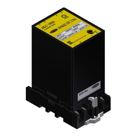
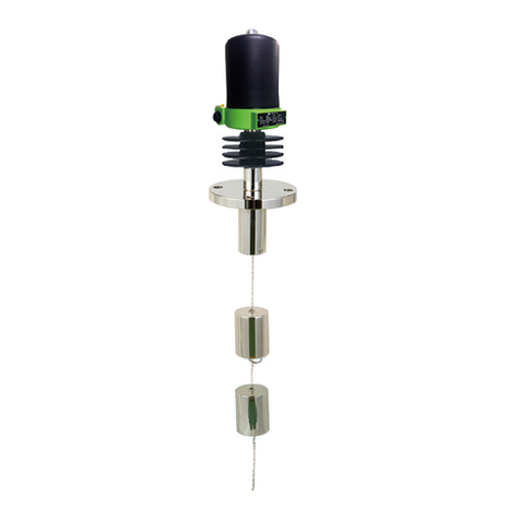
HITROL HCC-96RF-C Series User manual

HCC-96RF-C(S) Series
HITROL CO.,LTD. 1
HITROL CO., LTD.
HEAD OFFICE.FACTORY.R&D INSTITUDE
HITROL CO., LTD 141, Palhakgol-gil, Jori-eup
Paju-si, Gyeonggi-do, Korea
TEL.: (00)-82-31-950-9700
FAX: (00)-82-31-943-5600
www.hitrol.com
INSTRUCTION MANUAL
CAPACITANCE TYPE LEVEL SWITCH
HCC-96RF-C(S) Series
Doc. no. : HCC96RFC(S)_IM_Eng_Rev.1
Issue date: 2021. 01

HCC-96RF-C(S) Series
HITROL CO.,LTD. 2
You shall be careful where CAUTION is
marked to carry out the work.
You shall be aware of where NOTICE is
marked to carry out the work.
You shall be well-informed of the contents
where WARNING is marked before carrying
out the work.
Table of Contents
Overview ·······························3
Characteristics ···························3
Operating Principle ·····················3
Specifications ···························4
Product Composition ·····················5
Installation ·····························6
Precautions for Installation ·················6
Precautions for Attachment ················7
Wiring ·······························7
Precautions for Use ······················7
Precautions for Removal ···················7
Precautions for Grounding ·················7
Maintenance ·························8
Failure Check ······················8
Safety and Environment ··················8
Marking ····························9
Warranty and Contact ·····················9
APPENDIX
APPENDIX Q ·········HCC-96RF-C Setting Guide
APPENDIX S ·········HCC-96RF-S Setting Guide
APPENDIX H ···Serial USB Terminal Install Guide

HCC-96RF-C(S) Series
HITROL CO.,LTD. 3
Overview
Characteristics
Operating
Principle
HCC-96RF-C(S) Series is a Radio Frequency Type Level Switch, and it detects level of a
medium by sensing of capacitance value change caused by a dielectric constant of each
medium. HCC-96RF-S Series can solve the build-up phenomenon of the detection part
due to electro-conducting materials by using "Guard Technology Phase Shifting".
For HCC-96RF-C Series, if the level of the medium increases and the main probe comes
into contact with the medium, the impedance changes depending on the capacitance
value. Using phase change of the signal being measured according to change of
impedance, measure the presence or absence of the medium and output it to the relay
contact.
For HCC-96RF-S Series, compares the signal flowing from active sensing probe towards
ground with reference RF signal, when the medium is detecting. Since all material has
unique dielectric constant (relative permittivity) and conductance value that are different
from air, the impedance of the signal circuit is changed when medium touches the
probe. This change causes a shift in phase of the RF Signal. A phase difference between
the active signal and reference signal causes the output circuitry to operate. (This type
can only be applied to solid/dust.)
For cylindrical tank, the capacitance can be obtained as follow.
C : Capacitance of medium (pF)
ε: Relative dielectric constant
L : Length of Probe
D : Outer diameter of tank
d : Outer diameter of sensing probe
C =
■Compensation electrode type with double structured sensor (Only for HCC-96RF-S)
■Prevention of malfunction caused by material build-up on the sensor
■Solid structure and semi-permanent life cycle due to non-machinery parts
■Easy installation and calibration
■Operating can be checked at the site.

HCC-96RF-C(S) Series
HITROL CO.,LTD. 4
Specifications Product
Model
HCC-96RF-C
HCC-96RF-CH
HCC-96RF-S
Probe Type
Main Probe
Main +
Compensation Probe
Mounting
Flange or Screw
Ambient temperature
-20˚C ~ +60˚C
Process temperature
Max. 80˚C
Max. 150˚C
Max. 240˚C
Process Pressure
Up to 20kg/cm2
Up to 10kg/cm2
Power Source
AC 90~240V, 50Hz/60Hz (Std.) / DC +24V (Opt.)
Output Signal
DPDT
Contact Rating
AC 250V, 5A / DC 30V, 5A
Enclosure
Weather-Proof
Wetted Parts Material
SUS 316L + Teflon
SUS 316L + PPS
Process Connection
PT 1”Screw
50A JIS 10K RF
Housing ; Cable Entry
PBT ; 2-PF 1/2”(F),
IP65 (Std.)
AL. ; 2-PF 1/2”(F),
IP66 (Opt.)
AL. ; 2-PF 1/2”(F),
IP66
AL. ; 2-PF 1/2”(F),
IP66
Amplifier Specification
Module
M-96RFC
M-96RFS
Microprocessor
16 Bit Microprocessor
Oscillation Frequency
420KHz @ ±10KHz
154KHz @ ±10KHz
Dielectric Constant
1.5 @ Min.
Sensitivity (Adjustment)
1pF ~ 80pF
1pF ~ 20pF
Function (Adjustment)
■Measurement Range
■Relay Delay Time
■Relay Return Time
■Relay Out Control (Normal/Reverse)
Relay Delay Time (Adjustment)
0.5Sec. @ Min. / 1 ~ 10Sec. @ 0.1Sec. Resolution
Relay Return Time (Adjustment)
0.5Sec. @ Min. / 1 ~ 10Sec. @ 0.1Sec. Resolution
Relay Contact Out Control
Normal Close @ Default.
Status Indicator
Bi-Color LED [Green / Red / Orange]
Detection Indicator
Red LED
Relay Control Indicator
Green LED
UART
Monitoring
Ambient Temperature
-20˚C ~ +80˚C

HCC-96RF-C(S) Series
HITROL CO.,LTD. 5
Actual product may have a tolerance slightly.
Product Composition
The dimensions on the following pages are indicated in [mm].
Rod Type
Rod Type
■Connection Type
-Screw: PT 1”(Std.), NPT 1”, PF 1”, Others
-Flange: ANSI, JIS, DIN
■Material
-SUS 316L, Others
[Housing]
[Connection]
[Probe]
For HCC-96RF-C
Material: PBT
Material: Aluminum
* Flat Type can be used in liquids, but further verification is required at the head office as a sample.
Material: Aluminum
Rod Type
(Fully insulated Teflon)
Flat Type (*)
For HCC-96RF-C(H)
For HCC-96RF-S
For HCC-96RF-CH
For HCC-96RF-S
For HCC-96RF-C(H)
For HCC-96RF-S (Only Solid)

HCC-96RF-C(S) Series
HITROL CO.,LTD. 6
Installation
Precautions
for
Installation
- If more than one level switch is installed in a tank, the distance between each probe
shall be at least 300mm apart. (If the distance between probes is short, it may be
affected by the interconnection of the instrument, causing unstable operation.)
- For side mounting installation, an inactive rod shall be located at least 50mm inside of
tank, and it is recommended that the probe be tilted by 15 degrees to the horizontal
surface. (A foreign object between the nozzle and the probe may cause malfunction.)
- Protector shall have sufficient area to protect the sensor from incoming medium and
be installed at a distance that does not affect sensor operation.
- For side mounting installation, the cable entry shall be installed facing the ground to
maintain the waterproof function.
- When installing on the low level, carefully install the dead stock and material bridge.
- For outdoor installation, it is recommended to install the sun cover to avoid the effects
of temperature increases.
- In case of tank with stirrer, the probe shall be installed at a safe distance from the stirrer.
HCC-96RF-C(S) Series is generally used for high or low alarm with an installation on the side or
top of the tank and can be also applied to metallic or synthetic resin tank as there are no
restrictions on the material of the tank.
■Side Mounting Installation
- If the content has the characteristics of creating an excess sediment layer, the
product shall be installed at an angle of about 45 degrees.
- If the content has a high density, a protector shall be installed at least 200mm
above from the probe in order to protect the probe.
■Top Mounting Installation
- If the probe length is more than 1000mm, install a fixed bracket insulated at the bottom.
- Sensing probe shall be installed at least 500mm away from the side of the tank.

HCC-96RF-C(S) Series
HITROL CO.,LTD. 7
Precautions
for Attachment
Wiring
Precautions
for Use
Precautions
for Removal
Precautions
for Grounding
■Do not bend or extend the sensor randomly.
■Make sure to install the product and the cover first before supplying the power.
■Do not use if the temperature range of the installation exceeds -20℃to +60 ℃.
■Do not use if the protection grade requires a higher grade than its product. (IP66 for
AL. Housing or IP65 for PBT Housing)
■Do not use where vibration is present.
■Connect correctly AC(90~240V) or DC(+24V) power to the power specification.
■Make sure to connect the DC power with correct polarity(+, -).
■Do not connect the wire with the power connected.
■It provides DPDT output by default, wired COM and N.O terminals when using the high alarm.
■External grounding shall be completed.
■Check the level and presence of medium in the tank before removing it.
■Wear gloves when removing it, to prevent a burn.
■Disassemble work shall be done with the power off.
■Make sure that any O-ring or gasket is not damaged while opening or closing the
cover of product.
■The grounding has an external and an internal grounding. When connecting to an
external ground, the ground wire shall be 4㎟(4mmSQ).
■The internal grounding wire shall be the same size as the power line, and the size of
the internal grounding terminal lug shall be 3.1㎟(3.1mmSQ). If the power line is
larger than 3.1㎟, connect the ground wire without terminal lug.
Please do not apply high impact to the product.
Make sure to insert a washer if the terminal lug is removed from ground
terminal and then re- connected. (Loosening prevention)
■Connect the flanges or bolts with the same specifications.
■Make sure to insert washers between bolts and nuts to prevent loosening.
■Make sure to insert gaskets between flanges. (Select the gaskets in consideration of
the temperature of the content and the pressure inside the container.)
■Make sure to install the product and the cover before supplying the power.
■When installing the sensor, avoid shaking or obstacle.
■Condensation may occur if the temperature of the housing differs significantly from the
ambient temperature, so dehumidifier shall be filled or ventilated(gortex) before use.
When installing the product, use the tool to tighten it.

HCC-96RF-C(S) Series
HITROL CO.,LTD. 8
Maintenance
Failure Check
Safety and
Environment
The life span of key parts depends on user’s environment and can be used optimally through
periodic check. Therefore, regular inspection ensures optimal performance of product, so take
regular inspection and maintenance at least every year. Inspection of the appearance of the product
shall be visually checked to see if there is any damage, and the attachment of the medium or
foreign substances to the sensor will make it worse, so they shall be removed regularly.
■Precautions for Use
- Make sure to connect the product and vessel using required tools for sure.
- Keep the lock key safe and make sure that it is locked.
- Do not apply high impact to the product.
■Precautions for Wiring
- Make sure to wire contacts correctly.
- Wire and supply the power to the product after checking the specifications.
- Incorrect power voltage may cause damage to the product.
- Pay attention to prevent electric shock.
■Disposal of Product
- Make sure to separate the amplifier and main unit from housing before disposing
the products. Also, the amplifier shall be detached and discard the metal and non-
metallic materials. No part (ex. Mercury switch) has influence on the environment, so
no special attention is required.
If there is a problem with operation, check the following first.
■Is power voltage connected correct?
■Is power voltage supplied according to specifications correct?
■Is cable wiring correct?
■Is the Fail-Safe Mode setting correct?
■Does the green LED turn on?
Turn off the power of the product for maintenance.
HEAD External Grounding (PBT)
HEAD External Grounding (AL.C)
External Grounding
4㎟(4mmSQ)

HCC-96RF-C(S) Series
HITROL CO.,LTD. 9
Marking
Warranty
and
Contact
■Warranty and Service
This product is subject to the warranty for 2 years of shipment and unpaid service
will be provided for any damage found under normal operating conditions. If it is not
about the failure of product, the service charge will be payable.
You can request A/S at our website or by contacting our headquarters.
■Headquarters ․Factory ․Laboratory Contact Number
ADDRESS:
HITROL CO., LTD 141, Palhakgol-gil, Jori-eup, Paju-si, Gyeonggi-do, Korea
T E L : 031-950-9700 (Headquarters & A/S)
F A X : 031-943-5600 (Headquarters & A/S)
■Product Identification
- The product identification mark is attached onto the housing and shows the model
name, serial number, working temperature, working pressure, and matters regarding
output. The serial number is a unique manufacturing number for the identification of
products.

HCC-96RF-C
Setting Guide
RF Admittance Type Level Switch
Doc. no. : Rev0.0
Issued Date : 2020.11.18
APPENDIX Q

1. M-96RFC Configuration and Function
No
Configuration
Function
1
TUN.
■Tuning Capacitance in the tank
■Sensitivity Adjustment
2
DT.
■Relay Delay Time Adjustment
○Time Range: 0.5s, 1s ~ 10s @ Adjustment 0.1s
3
RT.
■Relay Return Time Adjustment
○Time Range: 0.5s, 1s ~ 10s @ Adjustment 0.1s
4
Fail Safe Mode
■Relay Transformation Adjustment
○N.C ↔N.O
5
DET.
■Measurement Status LED
○OFF →Red
6
RLY.
■Relay Status LED
○N.C: OFF →Green
○N.O: Green →OFF
7
PWR.
■Power & Status Display
8
UART
■M-96RFS Status Setting and Status Communication Port
9
Power
■Power Connector (AC / DC)
10
Relay Out
■Relay Contact Out (DPDT)

2. M-96RFC Setting and Adjustment
■Initialization Setting Method
□After installing it on the tank, set it to the initial state for quick response.
■Tuning Setting 1
□When the capacitance value in the tank is lower than the reference value,
No
Function
Method
1
Frequency Tuning
■To set the reference value while the
DET.
LED is off, adjust the
TUN.
VR
counter-clockwise until the
DET.
LED is on.
■Fine-tune
TUN.
VR clockwise until the
DET.
LED turns off.
[Before Adjusting
TUN.
VR]
[Adjusting
TUN.
VR]
[After Adjusting
TUN.
VR]
[Before Adjusting
TUN.
VR] [Adjusting counter-clockwise
TUN.
VR]
[Adjusting clockwise
TUN.
VR] [After Adjusting
TUN.
VR]

■Tuning Setting 2
□When the capacitance value in the tank is higher than the reference value,
■Sensitivity Adjustment Method
□You can adjust measurement sensitivity for each environment.
No
Function
Method
1
Frequency Tuning
■To set the reference value while the
DET.
LED is on, adjust the
TUN.
VR
clockwise until the
DET.
LED is off.
No
Function
Method
1
Tuning Setting Status
■The
TUN.
VR state according to the “Tuning Setting”is the most
sensitive state.
■Keep this status for sensitive use.
2
Sensitivity Adjustment
■You can adjust the sensitivity by adjusting
TUN.
VR.
■Sensitivity Adjustment Method
[Before Adjusting
TUN.
VR]
[After Adjusting
TUN.
VR]
[Before Adjusting
TUN.
VR]
[After Adjusting
TUN.
VR]
[Before Adjusting Sensitivity by
TUN.
VR]
[After Adjusting Sensitivity by
TUN.
VR]
[SENSITIVE]
[INSENSITIVE]

■Relay Time Adjustment Method
□You can adjust the relay operation time after detecting the measurement.
□You can adjust the relay return time after undetecting the measurement.
No
Function
Method
1
DT.
■Relay Delay Time
■Time Adjustment Range: 0.5s, 1s ~ 10s @ Adjustment 0.1s
No
Function
Method
1
RT.
■Relay Return Time
■Time Adjustment Range: 0.5s, 1s ~ 10s @ Adjustment 0.1s
[Operating Status According to Relay Return Time]
[Operating Status According to Relay Delay Time]

■Fail Safe Mode Adjustment Method
□You can adjust the contact status to Relay Contact N.C.
□You can adjust the contact status to Relay Contact N.O.
No
Function
Method
1
N.C
■Relay Contact Out Default Status
■After detecting the measurement, the contact point changes from N.C to N.O.
■LED Status
No
Function
Method
1
N.O
■Relay Contact Out Opposite Status.
■After detecting the measurement, the contact point changes from N.O to N.C.
■LED Status
[Operating Status According to Relay Contact [N.O]]
[Operating Status According to Relay Contact [N.C]]

3. M-96RFC UART Monitoring
■Monitoring Method
□You can only check the state of the adjusted setting values using PC or Smartphone.
□The execution method is the same using PC or Smartphone. (Password: 1975)
□Run Screen Component: You can check the sensor measurement status, sensitivity
setting value, relay setting, etc.
■Monitoring Method Using PC
□Component: PC, USB Cable(typical USB to Micro USB B), UART Adaptor.
[M-96RFC PC UART Component]
[USB Cable]
[M-96RFC PC UART Run Screen]
[M-96RFC PC UART Run Screen Component Function]
Relay Contact Status
Relay Return Time Setup Time State
Relay Delay Time Setup Time State
Current Measurement Voltage
(Non-detection: +3V / Detection: 0V)
Board Temperature

■Monitoring Method Using Smartphone
□Component: Smartphone(Android OS), OTG, USB Cable(typical USB to Micro USB B),
UART Adaptor..
□App: Refer to “Serial USB Terminal Install Guide”.
[USB Cable]
[M-96RFC Smartphone UART Component]
[M-96RFC Smartphone UART Execution]
[Open App]
[Home Screen]
[Select UART Connection]
[Enter Password]
[Run Screen]
[Enter exit command]
[Exit Program]
[Select UART Disconnection]
[M-96RFC Smartphone UART Exit]
[Enter PW and Fly command]
[Enter exit and Fly command]

HCC-96RF-S
Setting Guide
RF Admittance Type Level Switch
Doc. no. : Rev0.0
Issued Date : 2020.11.18
APPENDIX S

1. M-96RFS Configuration and Function
No
Configuration
Function
1
TUN.
■Tuning Capacitance in the tank
2
SEN.
■Sensitivity Adjustment
3
DT.
■Relay Delay Time Adjustment
○Time Range: 0.5s, 1s ~ 10s @ Adjustment 0.1s
4
RT.
■Relay Return Time Adjustment
○Time Range: 0.5s, 1s ~ 10s @ Adjustment 0.1s
5
Fail Safe Mode
■Relay Transformation Adjustment
○N.C ↔N.O
6
DET.
■Measurement Status LED
○OFF →Red
7
RLY.
■Relay Status LED
○N.C: OFF →Green
○N.O: Green →OFF
8
PWR.
■Power & Status Display
9
UART
■M-96RFS Status Setting and Status Communication Port
10
Power
■Power Connector (AC / DC)
11
Relay Out
■Relay Contact Out (DPDT)

2. M-96RFS Setting and Adjustment
■Initialization Setting Method
□After installing it on the tank, set it to the initial state for quick response.
■Tuning Setting
□Set the default capacitance value in the tank.
No
Function
Method
1
Frequency Tuning
■Tune the cap trimmer for setting the default value.
■Adjust clockwise until
DET.
LED turns off.
2
If the sensing LED does not turn off
(High capacitance in the tank)
■Adjust SEN. VR slightly clockwise and then readjust the cap trimmer.
SEN. : 0
Relay Delay Time: 0.5s
Relay Return Time: 0.5s
Fail Safe Mode (NC)
Cap Trimmer: Tuning
[Before tuning the cap trimmer]
[After tuning the cap trimmer]
This manual suits for next models
1
Table of contents
Other HITROL Laser Level manuals
