Big Dutchman BD-Blue 130 Manual
BD-Blue 130 Wall Fans
Technical User Guide
99-94-0854 04/2022 GB • 2022-04-28


BD-Blue 130 Wall Fans
Technical User Guide 3
Product and Documentation Changes
Big Dutchman reserves the right to change this document and the product herein described without further no-
tice. In case of doubt, please contact Big Dutchman.
The date of change appears from the front and back pages.
Note
• All rights belong to Big Dutchman. No part of this manual may be reproduced in any manner whatsoever
without the expressed written permission of Big Dutchman in each case.
• All reasonable efforts have been made to ensure the accuracy of the information contained in this manual.
Should any mistakes or imprecise information occur in spite of this, Big Dutchman would appreciate being
notified thereof.
• Irrespective of the above, Big Dutchman shall not accept any liability with regard to loss or damage caused
or alleged to be caused by reliance on any information contained herein.
• Copyright by Big Dutchman.

BD-Blue 130 Wall Fans
Technical User Guide
1 Product description ....................................................................................................................................... 8
2 Product survey ............................................................................................................................................... 9
2.1 BD-Blue 130 wall fans ............................................................................................................. 10
2.1.1 Type key .................................................................................................................................... 10
2.2 Accessories.............................................................................................................................. 14
3 Mounting guide............................................................................................................................................. 17
3.1 Recommended tools................................................................................................................ 17
3.2 Placement of BD-Blue 130 ..................................................................................................... 19
3.3 Preparing hole in wall.............................................................................................................. 19
3.3.1 Necessary space for BD-Blue 130 without LPC motor controller .............................................. 19
3.3.2 Necessary space for BD-Blue 130 with LPC motor controller ................................................... 19
3.3.3 Necessary space for BD-Blue 130 without cone........................................................................ 20
3.3.4 Measurements for square hole in wall ....................................................................................... 20
3.3.5 Measurements for square hole in wall with cone ....................................................................... 21
3.4 Measure and saw out the holes.............................................................................................. 23
3.5 Drainage holes ......................................................................................................................... 24
3.6 Mounting in wall....................................................................................................................... 25
3.6.1 Mounting with four brackets ....................................................................................................... 26
3.6.2 Mounting of four angle bars ....................................................................................................... 27
3.6.3 Mounting in wooden frame......................................................................................................... 28
3.6.4 Foaming ..................................................................................................................................... 29
3.6.5 Pointing ...................................................................................................................................... 32
3.7 Removing the transport bracket............................................................................................. 33
3.8 Mounting of inside safety net ................................................................................................. 34
3.9 Mounting of air controlled shutter ......................................................................................... 35
3.9.1 Outside air controlled shutter ..................................................................................................... 36
3.9.2 Inside air controlled shutter........................................................................................................ 38
3.10 Manual opening of motor controlled shutter ........................................................................ 40
3.11 Mounting of accessories......................................................................................................... 43
3.11.1 Cone .......................................................................................................................................... 43
3.11.2 Outside safety net ...................................................................................................................... 44
3.11.2.1 Without cone .............................................................................................................................. 44
3.11.2.2 With cone ................................................................................................................................... 45
3.11.3 Insulation plate........................................................................................................................... 46
3.11.4 Shading kit ................................................................................................................................. 47
3.11.5 Light trap .................................................................................................................................... 49
4 Installation guide.......................................................................................................................................... 50
4.1 Electrical connection............................................................................................................... 50
4.1.1 Disclaimer at retrofitting fans ..................................................................................................... 50
4.1.2 cUL............................................................................................................................................. 50
4.1.3 Mains supply dimensioning regarding harmonic distortion ........................................................ 50
4.1.4 Cabling to connection box and LPC motor controller................................................................. 51
4.1.5 Cabeling and placement of LPC motor controller ...................................................................... 51
4.1.6 Connection in the motor controller/frequency converter ............................................................ 52
4.1.6.1 Terminals for power supply........................................................................................................ 53
4.1.6.2 Terminals for power supply of fan.............................................................................................. 54
4.1.6.3 Signal terminals ......................................................................................................................... 54
4.1.6.4 Terminals on relay module......................................................................................................... 55
4.1.7 LED indication on the motor controller/frequency converter ...................................................... 56
4.1.8 Alarms........................................................................................................................................ 56
4.1.9 Emergency opening for BD-Blue 130 actuator – house controller............................................. 57
4.1.9.1 Fan active at power failure......................................................................................................... 57
4.1.9.2 Fan not active at power failure................................................................................................... 58
4.1.10 Connection in the actuator ......................................................................................................... 60

BD-Blue 130 Wall Fans
4.1.10.1 BD-Blue 130 LPC actuator time-controlled ................................................................................ 60
4.1.10.2 BD-Blue 130 LPC actuator stepless .......................................................................................... 60
4.1.10.3 BD-Blue 130 ON/OFF actuator .................................................................................................. 60
4.1.11 Connection of extra 24 V power supply ..................................................................................... 61
4.1.12 Cable plans and circuit diagrams............................................................................................... 62
4.1.12.1 General information about circuit diagrams ............................................................................... 62
4.1.12.1.1 Color code.................................................................................................................................. 62
4.1.12.1.2 Power supply isolator................................................................................................................. 62
4.1.12.1.3 Letter code ................................................................................................................................. 62
4.1.13 Circuit diagram for OFF/AUTO/ON switch ................................................................................. 63
4.1.13.1 BD-Blue 130 LPC....................................................................................................................... 63
4.1.13.2 BD-Blue 130 ON/OFF ................................................................................................................ 63
4.1.14 Circuit diagram for emergency opening ..................................................................................... 64
4.1.14.1 BD-Blue 130 LPC....................................................................................................................... 64
4.1.14.2 BD-Blue 130 ON/OFF ................................................................................................................ 64
4.1.15 BD-Blue 130 LPC with reverse (1x230 V).................................................................................. 65
4.1.15.1 Cable plan.................................................................................................................................. 65
4.1.15.2 Circuit diagram........................................................................................................................... 65
4.1.16 BD-Blue 130 LPC with alarm relay (1x230 V)............................................................................ 66
4.1.16.1 Cable plan.................................................................................................................................. 66
4.1.16.2 Circuit diagram........................................................................................................................... 66
4.1.17 CL 1400 LPC 1x230 V variable ON/OFF (60-25-4566) ............................................................ 67
4.1.17.1 Cable plan.................................................................................................................................. 67
4.1.17.2 Terminals in LPC 1x230 V fan ................................................................................................... 67
4.1.17.3 Circuit diagram........................................................................................................................... 68
4.1.18 BD-Blue 130 LPC 1x230 V stepless (60-25-4569) .................................................................... 69
4.1.18.1 Cable plan.................................................................................................................................. 69
4.1.18.2 Terminals in LPC 1x230 V fan ................................................................................................... 69
4.1.18.3 Circuit diagram........................................................................................................................... 70
4.1.19 BD-Blue 130 LPC 3x400 V variable ON/OFF (60-25-4562/60-25-4568) ................................... 71
4.1.19.1 Cable plan.................................................................................................................................. 71
4.1.19.2 Terminals in LPC 3x400 V fan ................................................................................................... 71
4.1.19.3 Circuit diagram........................................................................................................................... 72
4.1.20 BD-Blue 130 LPC 3x400 V with actuator – stepless (60-25-4560/60-25-4571)......................... 73
4.1.20.1 Cable plan.................................................................................................................................. 73
4.1.20.2 Terminals in LPC 3x400 V fan ................................................................................................... 73
4.1.20.3 Circuit diagram........................................................................................................................... 74
4.1.21 BD-Blue 130 LPC 3x230 V variable ON/OFF (60-25-4567) ...................................................... 75
4.1.21.1 Cable plan.................................................................................................................................. 75
4.1.21.2 Terminals in LPC 3x230 V fan ................................................................................................... 75
4.1.21.3 Circuit diagram........................................................................................................................... 76
4.1.22 BD-Blue 130 LPC 3x230 V stepless (60-25-4570) .................................................................... 77
4.1.22.1 Cable plan.................................................................................................................................. 77
4.1.22.2 Terminals in LPC 3x230 V fan ................................................................................................... 77
4.1.22.3 Circuit diagram........................................................................................................................... 78
4.1.23 BD-Blue 130 EL ON/OFF 1x230 V (60-25-4577/60-25-4578) ................................................... 79
4.1.23.1 Cable plan.................................................................................................................................. 79
4.1.23.2 Terminals in ON/OFF 1 x 230 V fan........................................................................................... 79
4.1.23.3 ON/OFF actuator control box..................................................................................................... 80
4.1.23.4 Circuit diagram........................................................................................................................... 80
4.1.24 BD-Blue 130 EL ON/OFF 3x400 V (60-25-4580)....................................................................... 81
4.1.24.1 Cable plan.................................................................................................................................. 81
4.1.24.2 Terminals in ON/OFF 3x400 V fan............................................................................................. 81
4.1.24.3 ON/OFF actuator control box..................................................................................................... 82
4.1.24.4 Circuit diagram........................................................................................................................... 82
4.1.25 BD-Blue 130 EL ON/OFF 3x400 V with thermal cutout (60-25-4581) ....................................... 83
4.1.25.1 Cable plan.................................................................................................................................. 83
4.1.25.2 Terminals in ON/OFF 3x400 V fan with thermal cutout ............................................................. 83
4.1.25.3 ON/OFF actuator control box..................................................................................................... 84
4.1.25.4 Circuit diagram........................................................................................................................... 84
4.1.26 BD-Blue 130 EL ON/OFF 3x230 V (60-25-4579)....................................................................... 85
Technical User Guide

BD-Blue 130 Wall Fans
Technical User Guide
4.1.26.1 Cable plan.................................................................................................................................. 85
4.1.26.2 Terminals in ON/OFF 3x230 V fan............................................................................................. 85
4.1.26.3 ON/OFF actuator control box..................................................................................................... 86
4.1.26.4 Circuit diagram........................................................................................................................... 86
4.1.27 BD-Blue 130 AIR ON/OFF 1x230 V (60-25-4583/60-25-4584).................................................. 87
4.1.27.1 Cable plan.................................................................................................................................. 87
4.1.27.2 Terminals in ON/OFF 1 x 230 V fan........................................................................................... 87
4.1.27.3 Circuit diagram........................................................................................................................... 88
4.1.28 BD-Blue 130 AIR ON/OFF 3x400 V (60-25-4586/60-25-4587).................................................. 89
4.1.28.1 Cable plan.................................................................................................................................. 89
4.1.28.2 Terminals in ON/OFF 3x400 V fan............................................................................................. 89
4.1.28.3 Circuit diagram........................................................................................................................... 90
4.1.29 BD-Blue 130 AIR ON/OFF 3x400 V with thermal cutout (435441-02) ....................................... 91
4.1.29.1 Cable plan.................................................................................................................................. 91
4.1.29.2 Terminals in ON/OFF 3x400 V fan with thermal cutout ............................................................. 91
4.1.29.3 Circuit diagram........................................................................................................................... 92
4.1.30 BD-Blue 130 AIR ON/OFF 3x230 V (60-25-4585) ..................................................................... 93
4.1.30.1 Cable plan.................................................................................................................................. 93
4.1.30.2 Terminals in ON/OFF 3x230 V fan............................................................................................. 93
4.1.30.3 Circuit Diagram .......................................................................................................................... 94
5 Maintenance instructions ............................................................................................................................ 95
5.1 Cleaning.................................................................................................................................... 95
5.1.1 Fan............................................................................................................................................. 95
5.1.2 Motor controller/frequency converter ......................................................................................... 95
5.2 Recycling/Disposal .................................................................................................................. 95
6 Troubleshooting instructions ..................................................................................................................... 96
7 Technical data .............................................................................................................................................. 98
7.1 BD-Blue 130 LPC 1x230 V ....................................................................................................... 98
7.1.1 ErP/Ecodesign BD-Blue 130 LPC 1x230 V.............................................................................. 100
7.2 BD-Blue 130 LPC 3x400 V ..................................................................................................... 101
7.2.1 ErP/Ecodesign BF 50 LPC 3x400 V ........................................................................................ 103
7.3 BD-Blue 130 LPC 3x230 V ..................................................................................................... 104
7.3.1 ErP/Ecodesign BD-Blue 130 LPC 3x230 V.............................................................................. 106
7.4 BD-Blue 130 ON/OFF EL 1x230 V ......................................................................................... 107
7.4.1 ErP/Ecodesign BD-Blue 130 ON/OFF EL 1x230 V.................................................................. 108
7.5 BD-Blue 130 ON/OFF EL 3x400 V ......................................................................................... 109
7.5.1 ErP/Ecodesign BD-Blue 130 ON/OFF EL 3x400 V.................................................................. 110
7.6 BD-Blue 130 ON/OFF EL 3x230 V/3x200 V........................................................................... 111
7.6.1 ErP/Ecodesign BD-Blue 130 ON/OFF EL 3x230 V.................................................................. 112
7.7 BD-Blue 130 ON/OFF AIR 1x230 V........................................................................................ 113
7.7.1 ErP/Ecodesign BD-Blue 130 ON/OFF AIR 1x230 V ................................................................ 114
7.8 BD-Blue 130 ON/OFF AIR 3x400 V........................................................................................ 115
7.8.1 ErP/Ecodesign BD-Blue 130 ON/OFF AIR 3x400 V ................................................................ 117
7.9 BD-Blue 130 ON/OFF AIR 3x230 V/3x200 V ......................................................................... 118
7.9.1 ErP/Ecodesign BD-Blue 130 ON/OFF AIR 3x230 V ................................................................ 119
7.10 Actuators ................................................................................................................................ 120
7.11 Metal and plastic parts .......................................................................................................... 121
7.12 Light traps .............................................................................................................................. 122
7.13 Number of wall fans in a container ...................................................................................... 123
8 Dimensioned sketch .................................................................................................................................. 124
8.1 BD-Blue 130 ........................................................................................................................... 124
8.2 LPC motor controller ............................................................................................................. 125

BD-Blue 130 Wall Fans
8.3 Light trap ................................................................................................................................ 126
8.4 Outside safety net.................................................................................................................. 126
Technical User Guide

BD-Blue 130 Wall Fans
8 Technical User Guide
1 Product description
BD-Blue 130 is a direct driven corrosion-free wall fan.
BD-Blue 130 is available with air controlled and motor controlled shutters.
The fan is available in several different versions focusing on low power consumption, as well as standard ver-
sions.
BD-Blue 130 can be mounted using a cone for optimal air output and reduced power consumption.
BD-Blue 130 is specially designed for harsh livestock house environments. This applies to both climatic and
electrical influences.

BD-Blue 130 Wall Fans
Technical User Guide 9
2 Product survey

BD-Blue 130 Wall Fans
10 Technical User Guide
2.1 BD-Blue 130 wall fans
2.1.1 Type key
Fan BD-Blue 130 C -7 DMS 400-3 50/60 3.1A 48900m3h T
Fan name
BD-BlueWall Fan
Fan size
In cm 130
Cone
With cone C
Shutter type
Air controlled
Motor controlled
Variable 0-100%
Variable 50-100%
ON/OFF
ON/OFF mot
0-100%
DMS
Fan characteristics
High flow
Low energy
-7
-6
Rated voltage
3x400 V AC
3x230 V AC
1x230 V AC
400-3
230-3
230-1
Supply frequency
50 Hz and 60 Hz
50 Hz
60 Hz
50/60
50
60
Power consumption
x,xA
Power consumption
Air output
xxxxxxm3h
Air output
Thermal cutout
T
Thermal cutout
60-25-4566 Fan BD-Blue 130-6 DMS 230-1-50/60 6.5A 43800m3/h
Fan control method - variable ON/OFF.
60-25-4569 Fan BD-Blue 130-6 0-100% 230-1-50/60 6.5A 43800m3/h
Fan control method - stepless.
Safety net outside must be mounted to comply with CE marking, in coun-
tries where this is required.
LPC motor controller
PM motor 1,5 kW.
0,7 m motor cable.
Is supplied assembled.
ErP 2015 approved.
60-25-4566 and 60-25-4569 should not be used for negative pressure
higher than 80 Pa.
BD-Blue 130 Wall Fans
Technical User Guide 11
60-25-4562 Fan BD-Blue 130-7 DMS 400-3-50/60 3.1A 48900m3/h
60-25-4568 Fan BD-Blue 130-6 DMS 400-3-50/60 2.45A 44100m3/h
Fan control method - variable ON/OFF.
60-25-4560 Fan BD-Blue 130-7 0-100% 400-3-50/60 3.1A 48900m3/h
60-25-4571 Fan BD-Blue 130-6 0-100% 400-3-50/60 2.4A 44100m3/h
Fan control method - stepless.
Safety net outside must be mounted to comply with CE marking, in coun-
tries where this is required.
LPC motor controller
PM motor 1,5 kW.
0,7 m motor cable.
Is supplied assembled.
ErP 2015 approved.
60-25-4562 and 60-25-4560 should not be used for negative pressure
higher than 100 Pa.
60-25-4568 and 60-25-4571 should not be used for negative pressure
higher than 80 Pa.
60-25-4567 Fan BD-Blue 130-6 DMS 230-3-50/60 3.8A 44000m3/h
Fan control method - variable ON/OFF.
60-25-4570 Fan BD-Blue 130-6 0-100% 230-3-50/60 3.8A 44000m3/h
Fan control method - stepless.
Safety net outside must be mounted to comply with CE marking, in coun-
tries where this is required.
LPC motor controller
PM motor 1,5 kW.
0,7 m motor cable.
Is supplied assembled.
ErP 2015 approved.
60-25-4567 and 60-25-4570 should not be used for negative pressure
higher than 80 Pa.
60-25-4577 Fan BD-Blue 130 ON/OFF mot 230-1-50 7.5A 41400m3/h
60-25-4578 Fan BD-Blue 130 ON/OFF mot 230-1-60 7.1A 40400m3/h
Fan control method - ON/OFF
Safety net outside must be mounted to comply with CE marking, in coun-
tries where this is required.
AC motor 1x230 V 1,2 kW.
0,7 m motor cable.
Is supplied assembled.
ErP 2015 approved.
60-25-4577 should not be used for negative pressure higher than 80 Pa.
60-25-4578 should not be used for negative pressure higher than 100 Pa.
BD-Blue 130 Wall Fans
12 Technical User Guide
60-25-4580 Fan BD-Blue 130 ON/OFF mot 400-3-50 3.3A 43500m3/h
60-25-4581 Fan BD-Blue 130 ON/OFF mot 400-3-50 3.3A 43500m3/h T
Fan control method - ON/OFF
Safety net outside must be mounted to comply with CE marking, in coun-
tries where this is required.
AC motor 3x400 V 1,2 kW.
0,7 m motor cable.
Is supplied assembled.
ErP 2015 approved.
60-25-4580 and 60-25-4581 should not be used for negative pressure
higher than 80 Pa.
60-25-4579 Fan BD-Blue 130 ON/OFF mot 230-3-60 5.6A 42400m3/h
Fan control method - ON/OFF
Safety net outside must be mounted to comply with CE marking, in coun-
tries where this is required.
AC motor 3x230 V 1,2 kW.
0,7 m motor cable.
Is supplied assembled.
ErP 2015 approved.
60-25-4579 should not be used for negative pressure higher than 90 Pa.
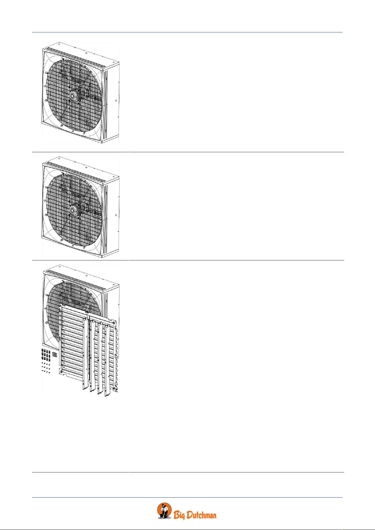
60-25-4583 Fan BD-Blue 130 ON/OFF 230-1-50 7.5A 42300m3/h
60-25-4584 Fan BD-Blue 130 ON/OFF 230-1-60 7.1A 40600m3/h
Fan control method - ON/OFF
Safety net outside or motor controlled shutter must be mounted to comply
with CE marking, in countries where this is required.
AC motor 1x230 V 1,2 kW.
0,7 m motor cable.
Is supplied assembled.
ErP 2015 approved.
The shutter system is supplied as knock down.
It is usually not recommended to use air controlled shutters due to lack of
emergency ventilation ability, risk of heat drainage, lack of control of air vol-
ume, deleterious wind action etc.
In areas with outside temperatures above 45 °C, air controlled shutters
must be mounted on the inside - alternatively, a cover must be established
for direct sun exposure of the shutter.
Insulation plate or light trap cannot be immediately used if the air controlled
shutter is mounted inside. If this solution is required, a frame for mounting
insulation plate or light trap must be established. Such a frame is not sup-
plied by Brand but must be produced locally.
60-25-4583 should not be used for negative pressure higher than 80 Pa.
60-25-4584 should not be used for negative pressure higher than 100 Pa.

BD-Blue 130 Wall Fans
Technical User Guide 13
60-25-4586 Fan BD-Blue 130 ON/OFF 400-3-50 3.3A 45100m3/h
435441-02 Fan BD-Blue 130 ON/OFF 400-3-50 3.3A 45100m3/h T
60-25-4587 Fan BD-Blue 130 ON/OFF 400-3-60 3.3A 43200m3/h
Fan control method - ON/OFF
Safety net outside or motor controlled shutter must be mounted to comply
with CE marking, in countries where this is required.
AC motor 3x400 V 1,2 kW.
0,7 m motor cable.
Is supplied assembled.
ErP 2015 approved.
The shutter system is supplied as knock down.
It is usually not recommended to use air controlled shutters due to lack of
emergency ventilation ability, risk of heat drainage, lack of control of air vol-
ume, deleterious wind action etc.
In areas with outside temperatures above 45 °C, air controlled shutters
must be mounted on the inside - alternatively, a cover must be established
for direct sun exposure of the shutter.
Insulation plate or light trap cannot be immediately used if the air controlled
shutter is mounted inside. If this solution is required, a frame for mounting
insulation plate or light trap must be established. Such a frame is not sup-
plied by Big Dutchman but must be produced locally.
60-25-4586 and 435441-02 should not be used for negative pressure higher
than 80 Pa.
60-25-4587 should not be used for negative pressure higher than 100 Pa.
60-25-4585 Fan BD-Blue 130 ON/OFF 230-3-60 5.6A 43300m3/h
Fan control method - ON/OFF
Safety net outside or motor controlled shutter must be mounted to comply
with CE marking, in countries where this is required.
AC motor 3x230 V 1,2 kW.
0,7 m motor cable.
Is supplied assembled.
ErP 2015 approved.
The shutter system is supplied as knock down.
It is usually not recommended to use air controlled shutters due to lack of
emergency ventilation ability, risk of heat drainage, lack of control of air vol-
ume, deleterious wind action etc.
In areas with outside temperatures above 45 °C, air controlled shutters
must be mounted on the inside - alternatively, a cover must be established
for direct sun exposure of the shutter.
Insulation plate or light trap cannot be immediately used if the air controlled
shutter is mounted inside. If this solution is required, a frame for mounting
insulation plate or light trap must be established. Such a frame is not sup-
plied by Big Dutchman but must be produced locally.
60-25-4585 should not be used for negative pressure higher than 90 Pa.
BD-Blue 130 Wall Fans
14 Technical User Guide
2.2 Accessories
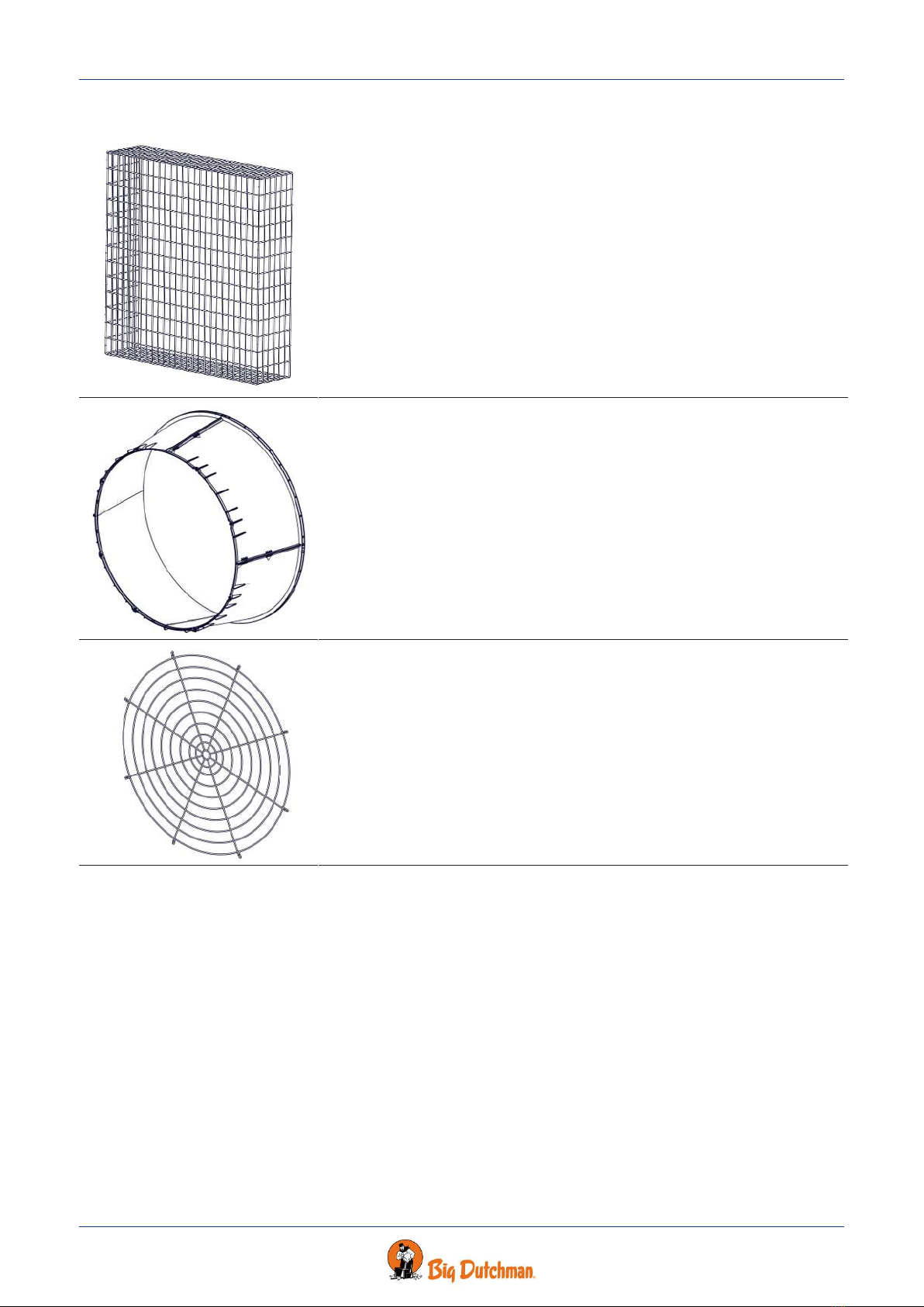
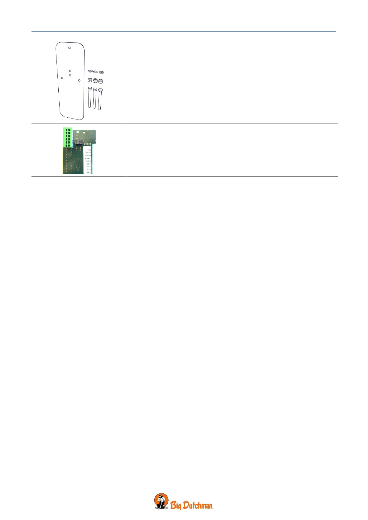
60-25-4459 BD-Blue 130 safety net outside wo/cone, A2
60-25-4458 BD-Blue 130 safety net outside wo/cone, galv
The outside safety net is used on BD-Blue 130 without cone where extra
safety is required.
Supplied with mounting parts.
One for each fan.
60-25-4457 BD-Blue 130 cone
The cone is used for ensuring better performance and energy efficiency.
Supplied with mounting parts.
1 per wall fan.
60-25-4460 BD-Blue 130 safety net outside for cone, A2
The outside safety net for cone is used where extra safety is required.
Supplied with mounting parts.
1 per wall fan.
BD-Blue 130 Wall Fans
Technical User Guide 15
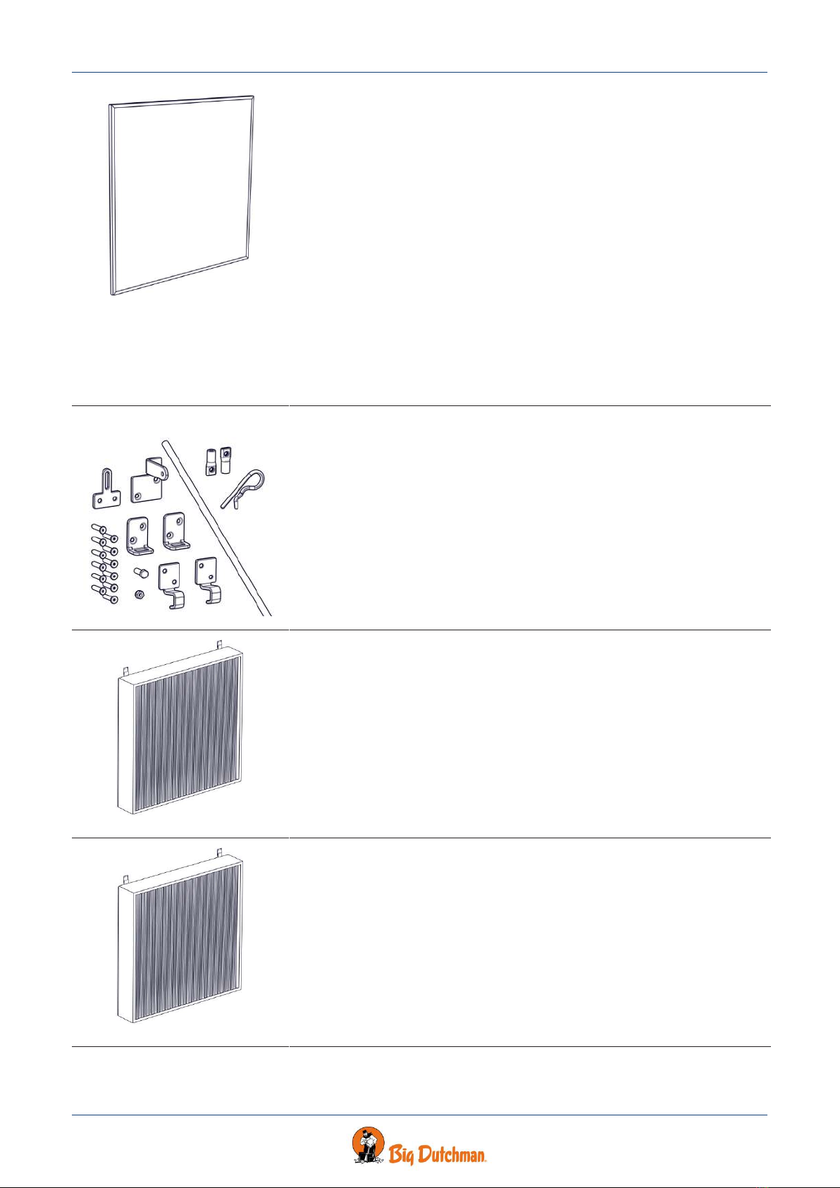
60-21-1413 BD-Blue 130 insulation plate
The insulation plate is used for mounting on a BD-Blue 130 wall fan where
extra insulation is necessary.
Used to avoid problems with condensation and cold air down draft, espe-
cially during the winter.
Insulation plates should always be used on all wall fans if dimensioned out-
side temperatures are below 0 °C.
Insulation plate cannot be immediately used, if the air controlled shutter is
mounted inside. If this solution is required, a frame for mounting insulation
plate must be established. Such a frame is not supplied by Big Dutchman
but must be produced locally.
The insulation plate is mounted and removed with only one handle.
H x W x D: 1380 x 1380 x 29 mm.
Includes various mounting parts.
1 per wall fan.
435442 50" shading kit for wall fan
The shading kit is used for light reduction when using insulation plate or an-
other type of plate.
It reduces the light from outside.
The shading kit contains mounting parts for mounting on plate and wall fan.
At an angle of 60 degrees measured between the fan and plate, the air out-
put will be reduced by approx. 5%
The shading kit can be used on all sizes of wall fans, provided the plate is
square.
1 per wall fan.
60-21-1409 50" light trap brown out
Used if dimming is required in the livestock house.
Light reduction factor 175.000:1.
The light trap reduces the air output of the fan without cone by approx. 15
% at 0-70 Pa pressure difference.
The light trap reduces the air output of the fan with cone by approx. 18 % at
0-70 Pa pressure difference.
Supplied as an unassembled unit incl. brackets.
1 per wall fan.
60-21-1412 50" light trap black out
Used if a large amount of dimming is required in the livestock house.
Light reduction factor 1.300.000:1.
The light trap reduces the air output of the fan without cone by approx. 31
% at 0-70 Pa pressure difference.
The light trap reduces the air output of the fan with cone by approx. 35 % at
0-70 Pa pressure difference.
Supplied as an unassembled unit incl. brackets.
1 per wall fan
BD-Blue 130 Wall Fans
16 Technical User Guide
435438 BD-Blue 130 support bracket kit f/air shutter
Is used to lift air controlled shutter. Can be used on both outside and inside
mounted air controlled shutters.
Supplied with mounting parts.
One for each fan.
81-39-4012 LPC-2 relay module
Used for mounting in motor controller/frequency converter, if an alarm out-
put is required or reversing of fan is required.
1 x potential free output relay 1 A, 30 V DC/24 V AC.
1 x digital input.
BD-Blue 130 Wall Fans
Technical User Guide 17
3 Mounting guide
Check that the parts ordered are present and undamaged before starting work. Please read through the entire
guide before starting assembly and fitting.
If the BD-Blue 130 is installed in areas with risk of ice/snow slide, precautions must be
made to avoid damage to the BD-Blue 130.
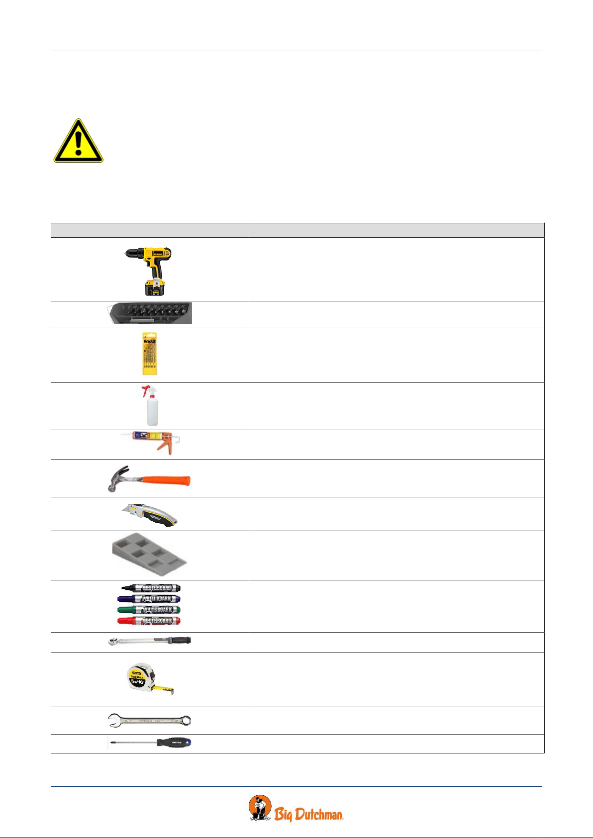
3.1 Recommended tools
A list of the recommended tools for mounting purposes can be seen below.
Item Description
Cordless drill
Screwdriver bits
Drill kit
Atomizer
Sealant gun
Hammer
Utility knife
Wedge
Marker pen
Torque wrench
Tape measure
Combination spanner kit
Screwdriver

BD-Blue 130 Wall Fans
18 Technical User Guide
Item Description
Foam gun
Ladder
Jigsaw
Socket wrench set
Spirit level
Try square
BD-Blue 130 Wall Fans
Technical User Guide 19
3.2 Placement of BD-Blue 130
BD-Blue 130 must be placed in the livestock house according to the drawing supplied. Contact Big Dutchman if
major changes are made.
Check that all BD-Blue 130 can be placed freely in relation to other housing equipment upon agreement with the
client.
Place the insulation of the brickwork all the way in against the BD-Blue 130 and all the way round (as in other
building constructions). This way you prevent a cold bridge along the side of BD-Blue 130 from being formed.
3.3 Preparing hole in wall
3.3.1 Necessary space for BD-Blue 130 without LPC motor controller
(B)
(C)
(D)
(E)
(A)
There must be a minimum of (A) space inside the live-
stock house for the wall fan.
There must be minimum of (B) of space including the
wall thickness outside the livestock house for the wall
fan.
Wall thickness (C).
The recommended space in front of the cone is (D).
Recommended installation height from floor is mini-
mum (E) in order to ensure space for dung removal.
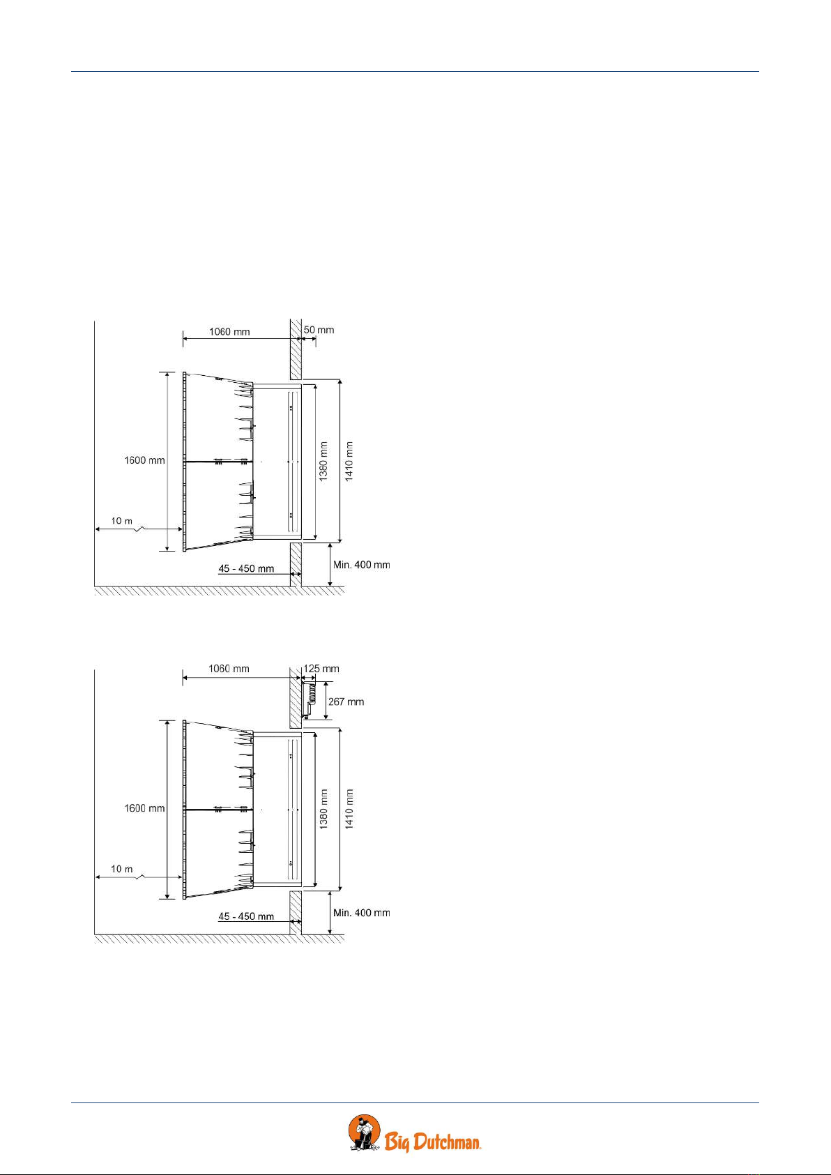
3.3.2 Necessary space for BD-Blue 130 with LPC motor controller
(B)
(C)
(D)
(E)
(A)
There must be a minimum of (A) space inside the live-
stock house for the wall fan.
There must be minimum of (B) of space including the
wall thickness outside the livestock house for the wall
fan.
Wall thickness (C).
The recommended space in front of the cone is (D).
Recommended installation height from floor is mini-
mum (E) in order to ensure space for dung removal.

BD-Blue 130 Wall Fans
20 Technical User Guide
3.3.3 Necessary space for BD-Blue 130 without cone
(B)
(C) (E)
(A)
(D)
There must be a minimum of (A) space inside the live-
stock house for the wall fan.
There must be minimum of (B) of space including the
wall thickness outside the livestock house for the wall
fan.
Wall thickness (C).
The recommended space in front of the cone is (D).
Recommended installation height from floor is mini-
mum (E) in order to ensure space for dung removal.
3.3.4 Measurements for square hole in wall
The dimensions below are given in mm .
Recommended measurements for individual mounting of BD-Blue 130 wall fan.
(A) Minimum distance is 550 mm, when mounting the LPC motor controller above BD-Blue 130.
(B) Minimum distance is 300 mm, when mounting the LPC motor controller between BD-Blue 130.
(A)
(B)
Table of contents
Other Big Dutchman Fan manuals


Popular Fan manuals by other brands

Schako
Schako NOVENCO NOVAX ACN ATEX Series Installation and Maintenance

Miele
Miele DA 239-3 Operating and installation instructions

GLP
GLP Force 120 operating instructions

O2cool
O2cool FC05002 manual

Breville
Breville Mistic 2 in 1 Connect LTF408 Instruction book

Sonnenkonig
Sonnenkonig AIR FRESH 5 user manual

NuTone
NuTone QTXEN080FLT instruction manual

Bionaire
Bionaire BAOF25M instruction manual

Svan
Svan SVVE16WT quick start guide

Ortech
Ortech ODD-ERV-80 instruction manual

Cromtech
Cromtech AP110002 Operation & instruction manual

National Ventilation
National Ventilation Monsoon MON-MEVH Installation and wiring instructions


