Bigassfans Powerfoil X3.0 User manual

Quick Installation Guide
Powerfoil®X3.0 LED Light
TO REDUCE THE RISK OF FIRE, ELECTRIC SHOCK, OR INJURY TO PERSONS, OBSERVE THE FOLLOWING:
WARNING: Disconnect power to the installation locations before installing the fan, controller, and LED light.
WARNING: Installation work and electrical wiring must be done by qualified person(s) in accordance with all
applicable codes and standards, including fire-rated construction. Incorrect assembly can cause electric shock or
damage the motor and the controller.
CAUTION: The Big Ass Fans product warranty will not cover equipment damage or failure that is caused by
improper installation or use.
BEFORE YOU START
Before beginning LED light installation:
1. Install the fan according to the Quick Installation Guide.
2. DISCARD the “LED Light Installation” instructions included in the box with the LED light.
3. Make sure the LED light will be installed on a separate circuit from the fan. The LED light and fan are controlled
separately. Connect the LED light to the lighting grid control, not to the fan control.
HARDWARE
(3) 1/4-20 x 1" Flange Hex
Head Cap Screws**
(3) 1/4-20 Hex Flange
Nylock Nuts**
(2) Ø3/32" x 2-1/2"
Cotter Pins**
(1) 3/4" Lock Nut
(2) Static Tube
Retainer Clips*
*One clip is provided with each static tube. Only one tube and clip are needed.
**Spare hardware included
***Included with fan mounting hardware
****Pre-installed to LED light
(1) 10-24 x 3/8"
Set Screw
(4) 10-16 x 1/2" Pan
Head Screws***
(8) M4 Socket Head
Cap Screws****
(8) M4 Lock
Washers****

1/4-20 x 1" Flange Hex
Head Cap Screw
2. POWER SUPPLY
Remove and discard the upper and lower screws securing the right side of the VFD cover. Mount the power supply
to the VFD.
1/4-20 Hex Flange
Nylock Nut
1. STATIC TUBE
Install either the “PFX” or “PFX-R” static tube according to the provided “Static Tube Retrofit” instructions. Refer to the
appropriate installation method for your fan’s motor frame type.
FANS THAT ALREADY HAVE A REMOVABLE STATIC TUBE
If your fan already has a field-installed (removable) static tube, uninstall the static tube, bracket, and clamp. Replace
with the provided static tube marked “PFX-R.” Refer to the provided “Static Tube Retrofit” instructions for installation
details.
If your fan already has a factory-installed (non-removable) static tube, remove the junction box and cotter pin from
the bottom of the static tube, and then proceed to step 2.
Refer to the “Static Tube
Retrofit” instructions
FANS THAT ALREADY HAVE A NON-REMOVABLE STATIC TUBE
3. POWER SUPPLY WIRING
GROUND GREEN IN
US/CA; GREEN W/ YELLOW
OUTSIDE US/CA
L1 BLACK IN US/CA;
BROWN OUTSIDE US/CA
L2 WHITE IN US/CA; BLUE
OUTSIDE US/CA
DIM
BLACK
DIM+
RED
POWER SUPPLY
GROUND
L1
L2
SUPPLY
POWER
DIM
GREY
DIM+
VIOLET
DIMMING
110 V DC
Supply voltage LED module’s L1
(black) connects to
LED module’s L2
(white) connects to
Low voltage
(120–277 V ± 15%)
120 VAC, 1 Ф derived from
1 Ф, 240/120 V panel H (black) N (white)
208 VAC, 3 Ф derived from
3 Ф, 208/120 V panel
L1 (black), L2 (red), or
L3 (blue)
L2 (red), L3 (blue), or
L1 (black)
240 VAC, 1 Ф derived from
1 Ф, 240/120 V panel L1 (black) L2 (red)
240 VAC, 1 Ф derived from
3 Ф, 240/120 V panel, B phase
wild
L1 (black), L2 (orange), or
L3 (blue)
L2 (orange), L3 (blue), or
L1 (black)
All
277 VAC, 1 Ф derived from
3 Ф, 480/277 V panel
L1 (brown), L2 (orange),
or L3 (yellow) N (white)
High voltage
(347–480 V ± 15%)
347 VAC, 1 Ф derived from
3 Ф, 600/347 V panel
L1 (red), L2 (black), or L3
(blue) N (white)
480 VAC, 3 Ф derived from
3 Ф, 480/277 V panel
L1 (brown), L2 (orange),
or L3 (yellow)
L2 (orange), L3 (yellow),
or L1 (brown)
480 VAC, 1 Ф derived from
3 Ф, 480 V panel, corner ground L1 (brown) or L3 (yellow) L2/Grounded conductor
(white or gray)
Refer to the input voltage marked on the LED light. Route power to the power supply and wire the power supply
according to the diagram and table below.

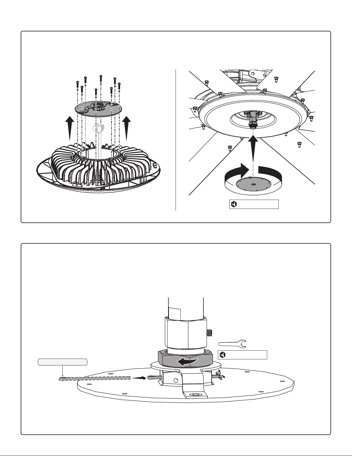
4. STATIC TUBE ADAPTER AND LOCK NUT
If your fan already has a factory-installed (non-removable) static tube, screw only the lock nut onto the static tube.
For all other installations, screw the static tube adapter onto the static tube, and then install the adapter set screw.
Tighten the set screw, and then screw the lock nut onto the static tube adapter.
3/4" Lock Nut
12 in·lb (1.36 N·m)
5. HUB COVER
Secure the hub cover to the hub. Skip this step if the hub cover is already installed.
10-24 x 3/8" Set Screw
Thread the lock nut
all the way onto the
threads, but do not
tighten.
1-1/8"
(29 mm)
Tighten until snug.
Static Tube
Adapter
10-16 x 1/2"
Pan Head Screw
6. LED LIGHT PLATE AND BRACKET
Remove the eight screws, eight lock washers, round plate, and bracket from the top of the LED light. Set the screws
and washers aside in a location where they will not get lost. Screw the plate and bracket onto the static tube or
static tube adapter until snug. Make sure one set of holes in the plate weld nut aligns with the holes in the static tube
or static tube adapter.
Tighten until snug.
7. COTTER PIN AND LOCK NUT
Using needle-nose pliers, insert the cotter pin through the holes in the plate weld nut and static tube or static tube
adapter. Bend back the ends of the cotter pin to lock it in place, and then tighten the lock nut.
For clarity, the fan and hub cover are not shown in the illustration.
Tighten until snug.
Ø3/32" x 2-1/2" Cotter Pin
1-3/8"
(35 mm)
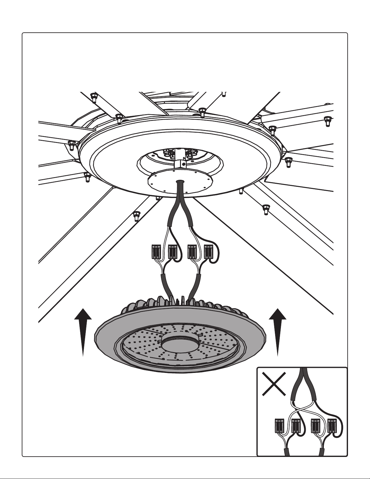
8. LED LIGHT WIRING
Route the DC wires from the power supply through the static tube. Depending on the wattage, the power supply will
have one cable with two wires or two cables with two wires. The LED light will also have one cable with two wires or
two cables with two wires. If necessary, trim the power supply cables to eliminate excess wiring.
Raise the LED light to the fan. Connect the power supply wires to the LED light wires of the same color. Connect each
pair of power supply wires (if applicable) to the same pair of LED light wires. Do NOT connect individual power
supply wires to dierent pairs of LED light wires.
LED light weight: 26.5 lb (12 kg)
Do NOT connect
individual power supply
wires to dierent pairs
of LED light wires.
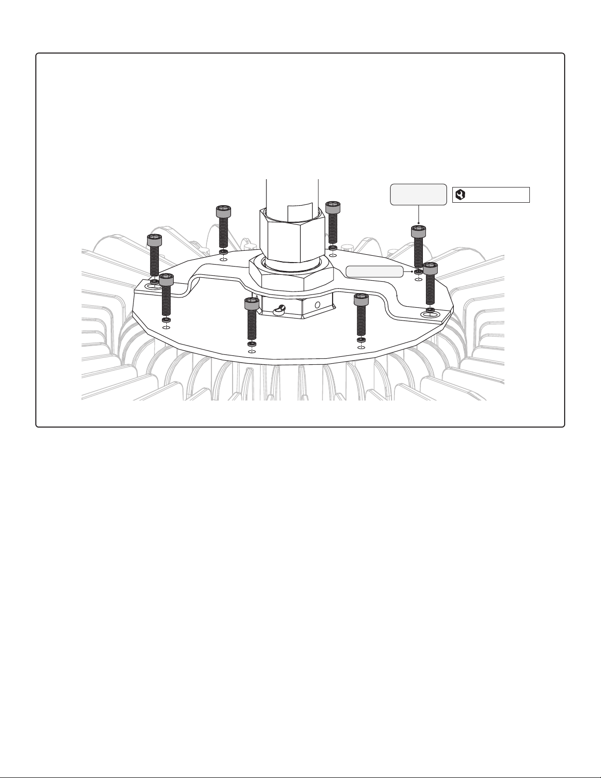
9. PLATE HARDWARE
Carefully pull the power supply cable(s) up into the static tube from the top. Tuck the LED light cables and connectors
inside the LED light module. Tuck ONLY the LED light cables and connectors inside the LED light module. Do NOT
tuck the power supply cables into the light module.
Raise the LED light to the round plate at the bottom of the static tube until the screw holes on top of the light align
with the screw holes on the plate. Reinstall the eight socket head cap screws and lock washers into the top of the
plate.
For clarity, the fan and hub cover are not shown in the illustration.
10 in·lb (1.13 N·m)
M4 Socket Head
Cap Screw
M4 Lock Washer

© 2020 DELTA T LLC ALL RIGHTS RESERVED.
PX3-INST-347-ENG-01 REV A 10/27/2020
NOTES
Other manuals for Powerfoil X3.0
1
Table of contents
Other Bigassfans Lighting Equipment manuals


