5
J
J
L
H
W
max. 10m / 33 feet
Assembly instruction Date:18.09.17
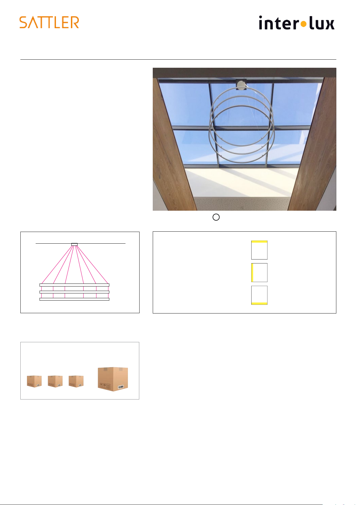
INSIEME
Ø 1240 - 1900 mm / 48.8 - 74.8“
NA: Ø 900 - 1900 mm / 35.4 - 74.8“
1
Ring-Distance
20 cm/7.9“
Ø cover plate
Ø body
H
2
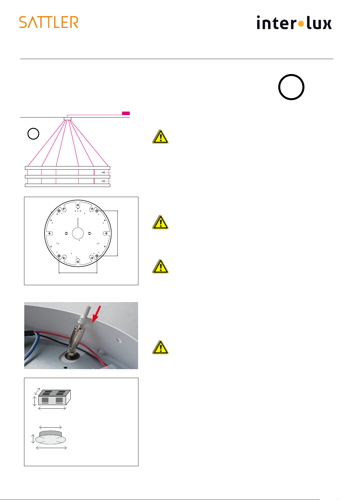
Light fixture with canopy –
Connection of the light fixture
with current-carrying steel cables
and external power supply unit
Mounting of the canopy
Make sure the ceiling has sufficient support capacity!
1. Open the canopy (4 screws on the side). Fit the base of the
canopy to the ceiling with the 4 mounting points. Ø Drill 6mm /
1/4“ holes and anchor to fasten canopy to ceiling 1.
2. Connect dead mains and dimming cable to the terminal
block of the ceiling plate (see wiring diagram page 7).
Connection of the light fixture
3. Fix light fixtures with 6 steel cables to the canopy using the
provided cable grippers.
Check alignment of the life cables and corresponding
cable holder
4. Bring the light fixture into desired position by using the steel cables
up or pushing the insulated nipple to loosen the cable. 2.
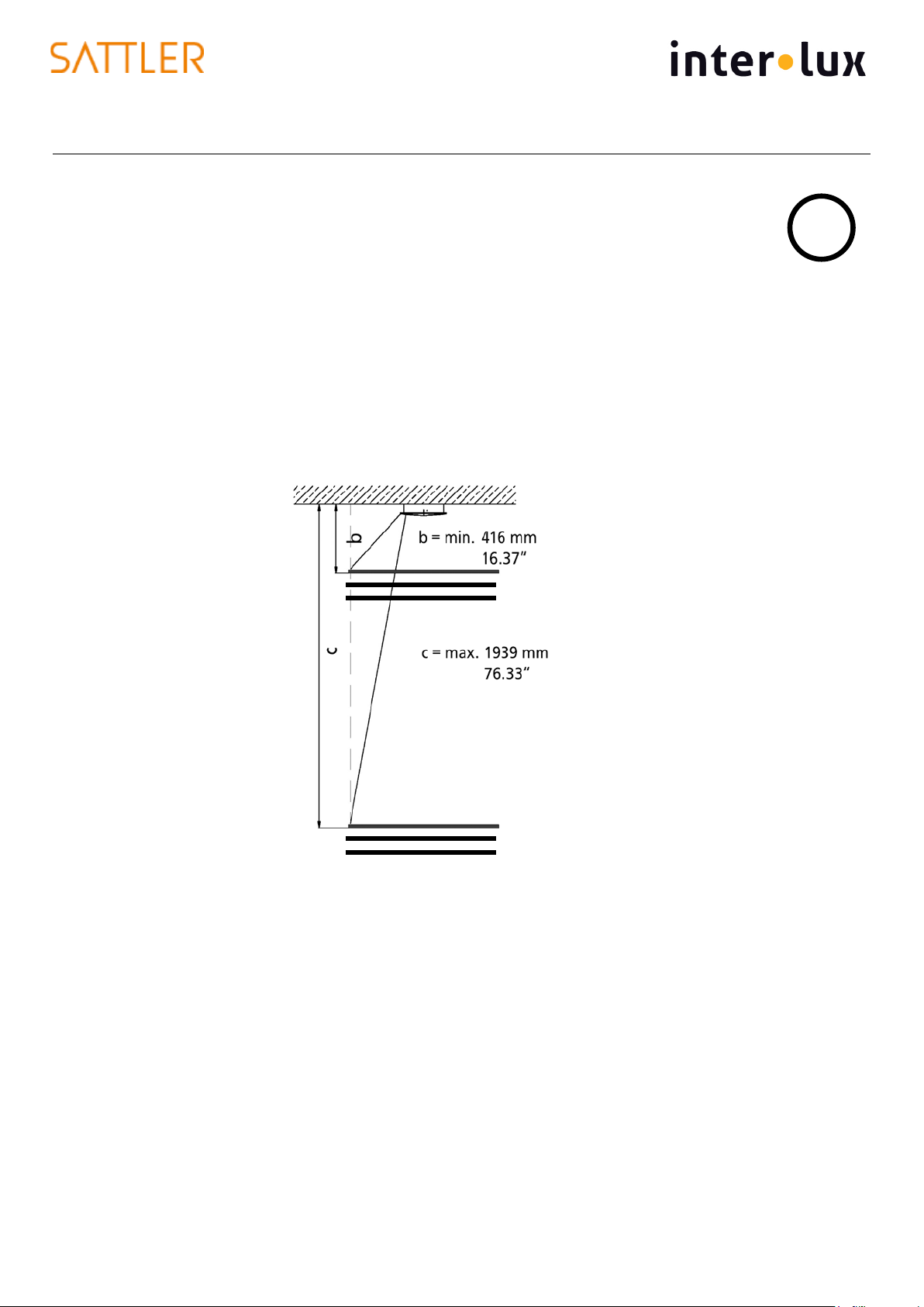
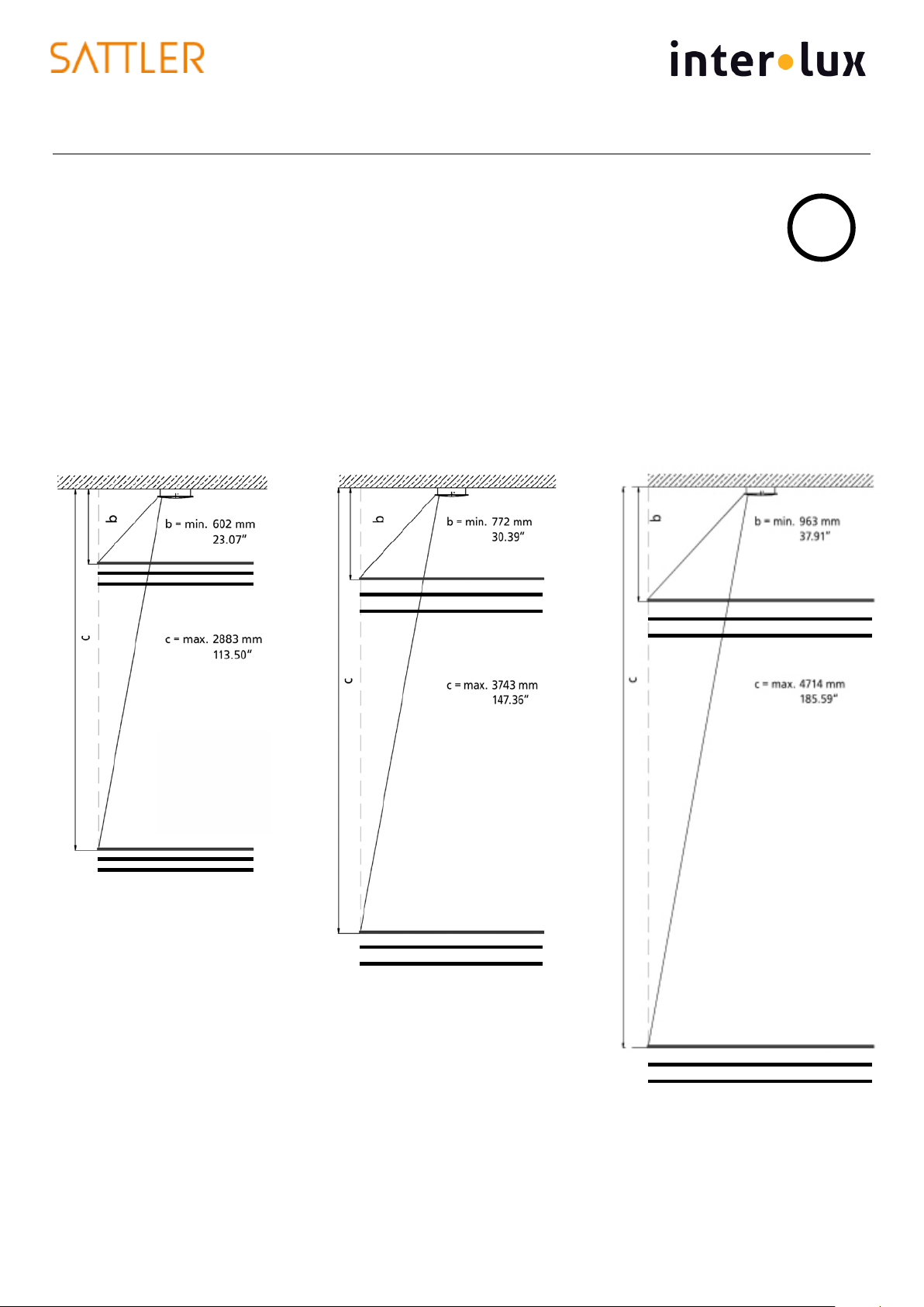
Observe minimum / maximum suspension height on page 4.
Consider the polarity of the current-carrying cables in
accordance with the markings on the light fixture and the
canopy.
Never adjust the suspension under pressure. The steel
cables might get damaged.
5. When the final position of fixture is given, tighten the insulated
lock nut/nipple and cut the steel cable in the canopy. If you want
to change the height of the light fixture later on, isolating the steel
cable within the canopy is also an option.
Not doing so will cause irreparable damage and shorting!
Shortened cables can only be replaced by the factory!
Assembly of the operating unit, connection to canopy
Mount external power supply unit only in a dry and aerated place!
Power supply cable from the operating unit to the light fixture max. 10m
/ 33 feet
Assembly of external power supply vertically or horizontally (see sketch)
7. Open the housing of the operating unit by loosening the 4 screws.
8. Fasten operating unit sufficiently.
9. Connect primary connection and power supply cable to the
canopy according to the wiring diagram (p.7), then fasten the
housing of the operating unit again.
6. Mount the canopy cover and fasten it with screws from the side.
10. Check whether the light fixture is functioning.
Power supply DE 2F
L360 x W300 x H85 mm
L14.2 x W11.8 x H3.3“
+
Canopy DB 350
Ø 350 / 320 mm
Ø 13.7 x 12.6“
H 60 mm / 2.3
Canopy Ø 350 mm / 13.7“ with 6 steel cables
194mm / 7.6“
194mm / 7.6“