BIL Skoots User manual

Depth Width
Height
380mm 600mm120mm 150mm
Model Dimensions (mm) SWL
pair
Wheel
diameter
Lifting
height
Toeplate
(A or B)
Total weight
pair
H W D
SK600 1160 510 330 600kg 125mm 400mm A 87.2kg
SK900 1160 510 330 900kg 125mm 400mm A 98.2kg
SK1400 1160 510 330 1400kg 125mm 400mm A 98.6kg
SK2000 1160 510 330 2000kg 125mm 400mm A 94.0kg
SK3500 1160 510 400 3500kg 125mm 375mm A 99.4kg
SK5000 1170 790 490 5000kg 150mm 200mm B 230.0kg
Each set of Skoots is supplied with a matching pair of
main frames which are designed to work at opposite
ends of the load. A pair of heavy-duty straps is
supplied to bind the Skoots units tightly to the load.
Skoots are portable moving systems which
hydraulically lift a load of up to 5000kg* off the
floor onto castors, allowing easy movement in any
direction. For heavy and bulky loads of all shapes and
sizes they can be used in a wide range of commercial
and amenity situations...
•Air conditioning installation & maintenance
•Commercial refrigeration
•Security safe installation
•Switchgear panel manufacture & installation
•Vending machine installation
•Museums and galleries
•Hire shops – speciality lifting equipment
•Data cabinets and server equipment
•Machinery installation
and many more...
* Load capacity according to model number
Toe plate A Toe plate B
Website: Www.liftingequpmentuk.com
Email: [email protected]

Check Skoots units for loose or missing nuts and bolts, stress cracks, worn wheel treads, bearings
and general wear and tear – and any missing ancillary equipment such as straps.
Keep within the safe working load as designated on the side of the Skoots units – remember, load
capacity is for a pair of Skoots not per side.
Keep the working area and transport route free from hazards such as debris, electrical cables,
potholes, deep gullies, large gaps between floor and goods lifts.
Ensure that the working area and transport route are adequately lit.
Lift the load evenly and use minimum ground clearance when transporting loads.
Ensure you can see where you are going or get a colleague to guide you.
Push but do not pull loaded Skoots.
Watch the Skoots unit and load at all times during any movements.
Use protective pads between the Skoots frame and the load if considered necessary.
Underestimate weight and overload the Skoots units.
Raise a load without it being fully secured by correctly positioned straps – see operating instructions.
Raise the load higher than necessary.
Raise a top-heavy, high-centre-of-gravity load by more than 20mm to avoid the risk of overbalancing.
Remove straps or release tension while a load is in a raised position.
Place your hands, feet or other under the load or moving parts when the load is raised.
Use Skoots units on a hill or incline without prior full risk assessments.
Move the load faster than is safe to ensure that you can keep it under control and upright.
Leave a raised load unattended.
Attach cranes or other lifting tackle to Skoots units.
Interfere with seals or hydraulics.
Attempt the lifting and moving procedure without wearing safety shoes to avoid the risk of injury from
the load potentially rolling over and crushing feet.
Attempt to engage/disengage directional locks on castors whilst the load is raised or on a gradient to
prevent the risk of a crushing injury caused by uncontrolled loaded equipment.
Use other equipment to move loaded Skoots. They are designed to be manually propelled unless when
used with a BIL Group recommended product such as PowerDrive.
Failure to follow user instructions carefully each time could result in serious
injury or death, or damage to property.
Website: Www.liftingequpmentuk.com
Email: [email protected]
2. Place Skoots units centrally under each end of the
load, ensuring that the load is located firmly in the heel
of the toe plate. Note that the toe plate will try to push
away from the load whilst the top of the frame will
try to push into the load. Use protective pads, such as
carpet tiles, between the Skoots frame and the load if
considered necessary.
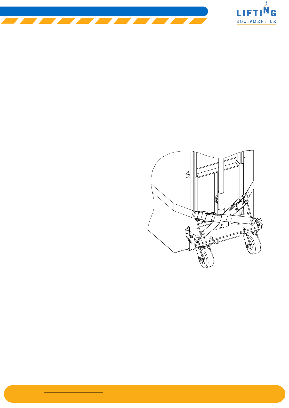
3. Secure load using both straps, ensuring that they
are hooked into the eyebolts at each end and cross at
the back of the Skoots units. It is important to cross
the straps over at the rear of the Skoots frames to
allow the position of the cam buckle to sit behind the
frame rather than at the side of the load. This also
enables the straps to be fixed at greater tension than
would otherwise be the case.
4. SK600 to SK3500 models: Pull the strap tight so
that the Skoots units are hard against the load, and
close the over-cam buckle to lock so that the straps
are held firmly.
SK5000 model: Pull the strap tight so that the Skoots
units are hard against the load before using the ratchet
lever to tightly lock the strap.
IMPORTANT: Be careful not to over-tighten the straps
as this may damage the load if its outer frame casing
is weak.
WARNING: Potential crush injury or damage to
property. Do not attempt to raise the load without
using straps to secure the load.
Pay close attention to the safety notes opposite before attempting to use your Skoots units.
1. Ensure the load is within the safe working capacity
of the Skoots as identified by the data plate affixed to
the Skoots, all the floors are suitable for the total load
and that the route is clear of all hazards. A formal risk
assessment should be carried out by a competent
person, if necessary.
IMPORTANT: Consider the floor surface and
structure before attempting to transport a load,
floors should be suitably boarded or plated first if
necessary.
Straps cross over at rear
of load, hooked to the
eyebolts with cam buckles
behind the Skoots frames
Website: Www.liftingequpmentuk.com
Email: [email protected]
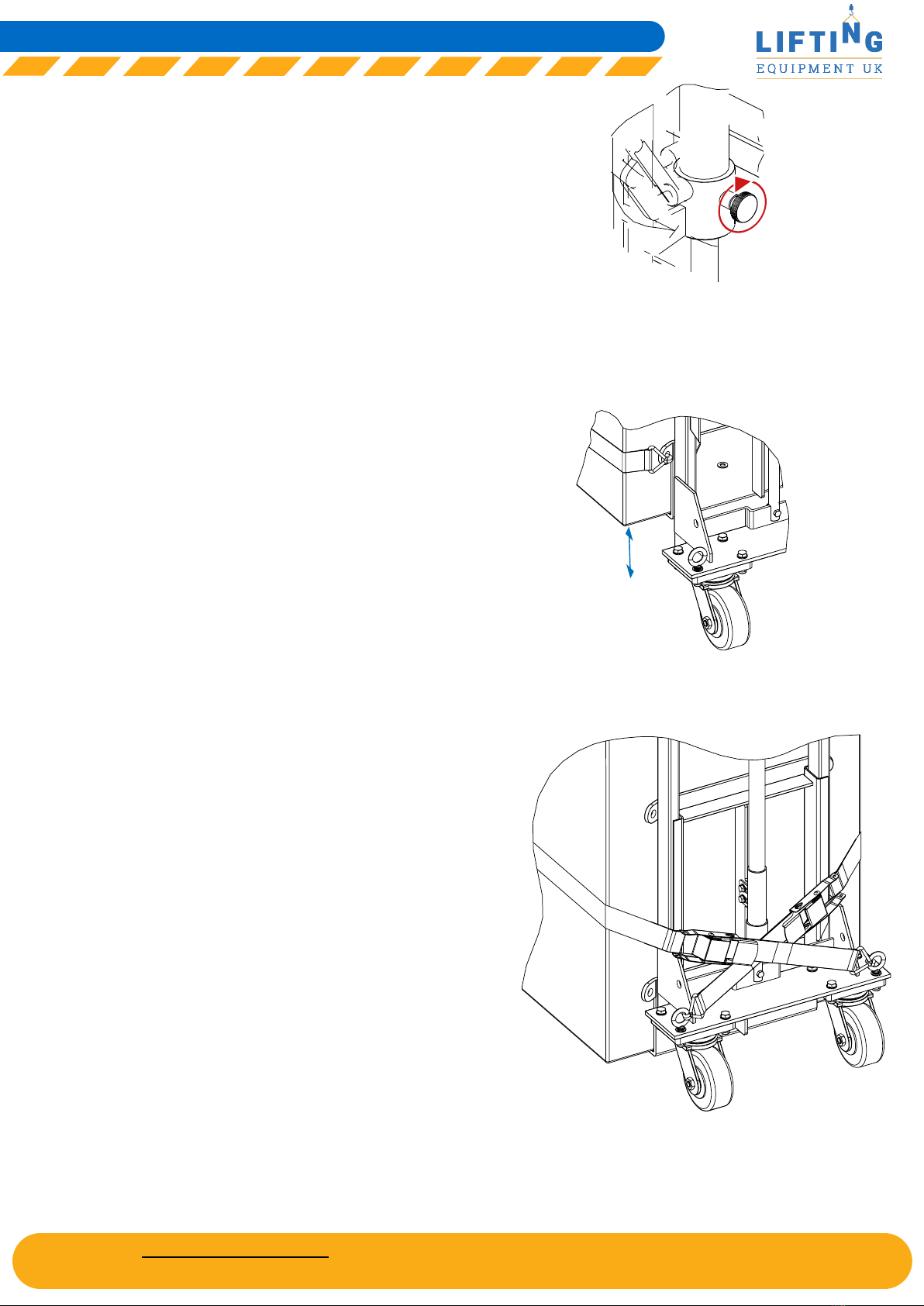
5. Before attempting to lift the load, close the
relief valve by turning the valve wheel clockwise
on the side of the jacks on both Skoots frames.
Do not over tighten as this could damage the jack.
The load is now ready for lifting.
6. Use the pump handles on the jacks maintaining
slow, full strokes to raise the load to obtain the
minimum ground clearance of about 20mm. Lift
evenly, alternating each end to keep the load
horizontal.
NOTE: Attempting to lift loads which are greater
than SWL will activate the relief valve. Whilst
the jack handle can still be pumped, the toe plate
will not raise until the load is reduced to within
safe SWL.
IMPORTANT: The default method of strap
engagement crossing straps over behind each
frame should be used to raise a low-centre-
of-gravity load to no more than 200mm when
the load is intended to remain in a stationary
position, for example when removing the load
from a plinth or block. It should also be used
when transporting a load at the minimum
ground clearance height of no more than 20mm.
However, if the user wishes to raise the load
to a maximum lift height of over 200mm then
the straps should be fixed to the Skoots using
the eyelets on the toe plate rather than the
eyebolts at the rear of the frame before the load
is raised. Proceed to raise the load first to the
desired height, and then lower it back to the
floor when the straps should be reconnected to
the eyebolts, crossing the straps over behind the
frame before transporting the load.
Never attempt to remove the straps whilst the
load is raised, never attempt to transport a
raised load at more than the minimum ground
clearance level of no more than 20mm and never
raise a top-heavy, high-centre-of-gravity load
more than 20mm from the floor regardless of
strap positions.
Stationary load
raised to 200mm+
Then revert to default strapping
method before attempting to
transport the load...
200mm+
Website: Www.liftingequpmentuk.com
Email: [email protected]
7. You may now move the load, pushing rather than
pulling.
IMPORTANT: For safety, the load should be
transported with a minimum ground clearance of
around 20mm to reduce the risk of overbalancing.
8. Make sure that control and stability of the load is
maintained at all times. On cambers and slopes use
the direction locks fitted to the castors.
WARNING: Safety risk assessments by a competent
person should be conducted before attempting to
transport loaded Skoots on cambers or slopes.
Never attempt to push a load over a drop such as a
kerb or over a gully.
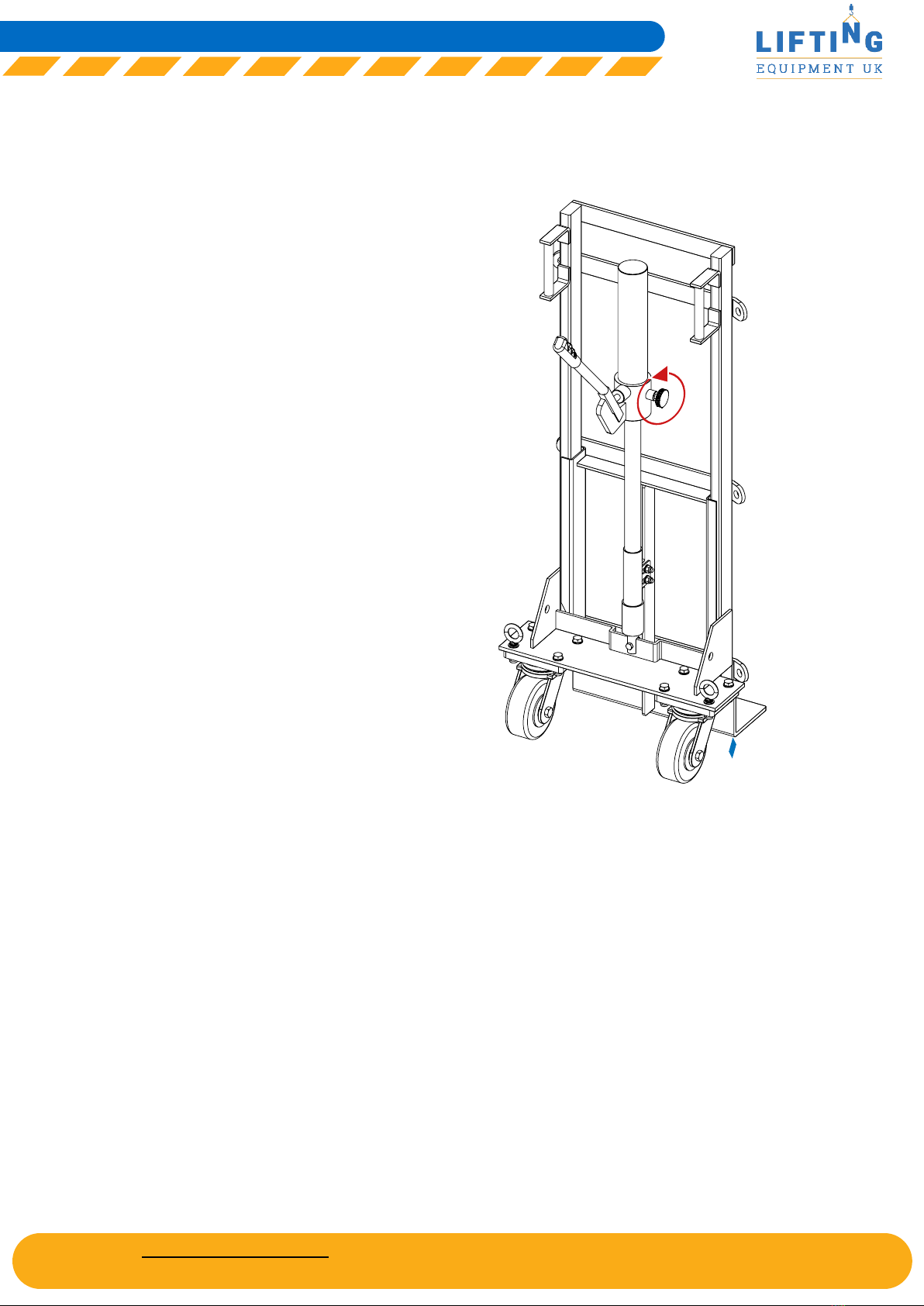
9. Once the load is in position, release the valve
wheels approximately one quarter turn anti-
clockwise, remembering that the less open the
release valves are, the slower the load is lowered.
WARNING: Potential crush injury. Open the valve
very slowly to control the rate of descent. Do not
lower the load without first checking for obstacles
underneath the load.
The load should be lowered in tandem by both
users at either end. Be careful to keep the load level
continuously as it is being lowered.
10. Release and remove the straps from the Skoots
and then the Skoots from underneath the load.
11. The Skoots units should then be stored in an
upright position.
No more than 20mm
ground clearance for
dynamic loads
20mm max
Turn anti-
clockwise
to lower
loads
Website: Www.liftingequpmentuk.com
Email: [email protected]

Unit lifts when pumped
but lowers when the
handle returns to the
rest position.
Unit will only lift a few
inches.
Handle pumps but will
not raise.
Oil leakage.
Load slipping on toe
plate.
Airlock.
Lack of oil.
Pressure relief valve
actuated.
Pumping handle too
quickly.
Worn or damaged
seals.
Worn or damaged
rubber mats.
Load incorrectly
secured. Tied with
loose straps.
Frames not
supported against
the side of the load.
Untighten the jack filler plug. Release the valve wheel
one quarter turn and pump handle 20 to 30 times.
Close the jack filler plug.
Stand jack vertically, fully retract ram and remove
filler plug using an 8mm allen key. Remove dipstick,
wipe clean, reinsert into oil and check oil level. Top
up with Varpress 68VG oil so fluid level is between
notched markers on the dip stick plug. Refit and tighten
down filler plug using the correct 8mm allen key.
Check load is within SWL and not unevenly
distributed. Reduce the load to within the marked
SWL as necessary. Consider upgrading to a higher
rated model if required.
Pump handle with slow, steady strokes.
Jack should be serviced or replaced with a new
exchange unit.
Replace rubber mats. Use recommended 3M
ScotchWeld 80 spray on prepared surfaces.
Check straps are correctly fitted and are under
tension without crushing the load. Ensure load is also
seated into the heel of the toe plate.
Ensure that the Skoot frames are presented to
a flush, vertical face on the load which extends
vertically through the full height of the Skoots frame.
Keep Skoots in an upright position at all times including during
transportation and storage to avoid airlocks in the hydraulic jacks.
If an airlock is present then refer to first symptom above.
Website: Www.liftingequpmentuk.com
Email: [email protected]
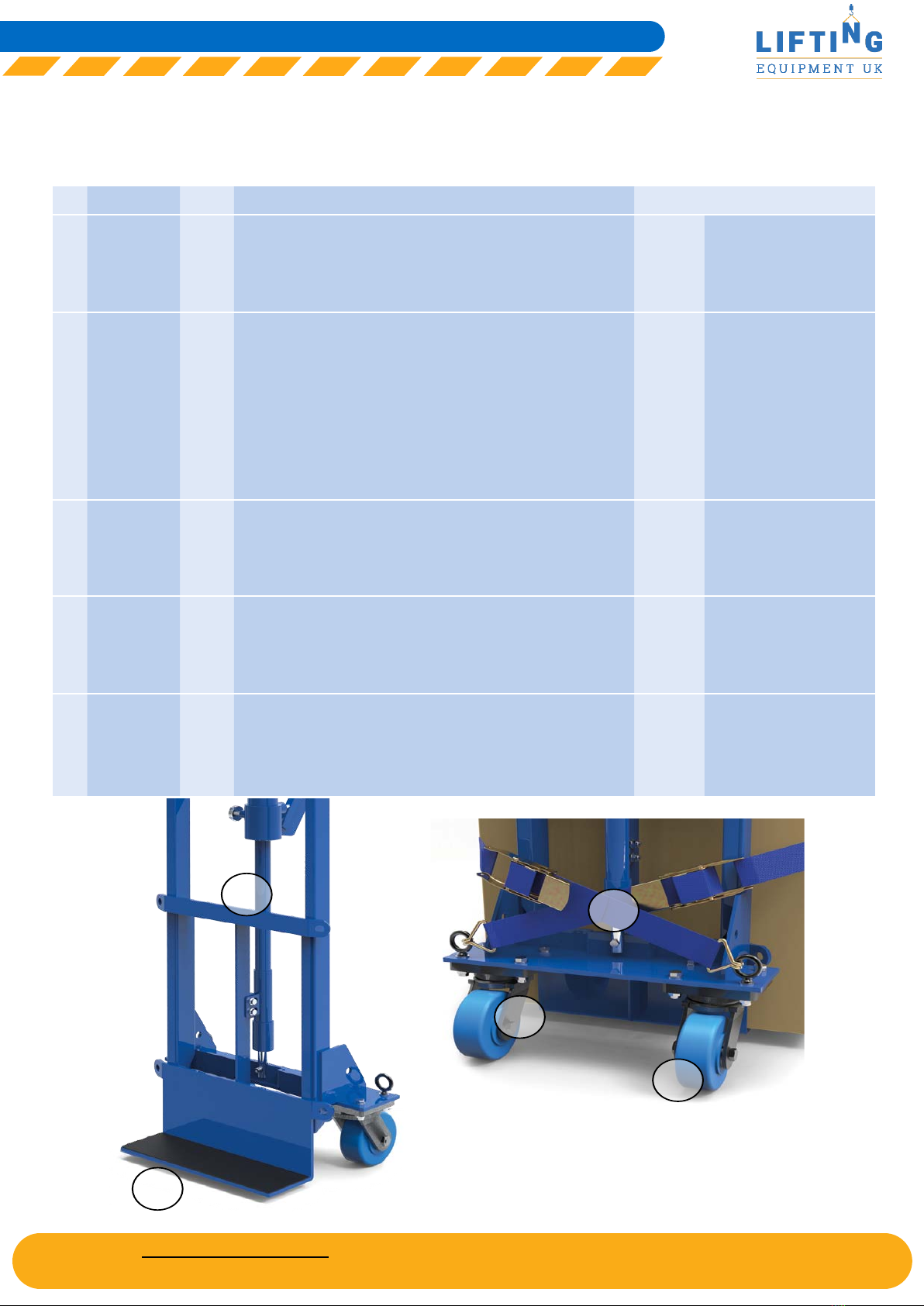
1 Main body
castor
Single Steel fabricated heavy-duty bracket. Directional lock. SK600
SK900
SK1400
SK2000
SK3500
SK5000
BZJ125NYBJDL
2BZSAB125ENPBJDL/SK
2BZSAB125XPNBJDL/SK
BZSAB125NYBJDL/SK
BZSAB125NYBJDL/SK
2BZQX150NYBJDL/SK
2 Main body
castor wheel
Single SK600: 125mm dia. white nylon with ball bearing, tread width 45mm
SK900: 125mm diameter, 82 shore A
Blue PU on nylon with ball bearing, tread width 40mm
SK1400: 125mm diameter, 97 shore A
Blue PU on nylon with ball bearing, tread width 49mm
SK2000: 125mm diameter
Blue HD solid cast nylon with ball bearing, tread width 55mm
SK3500: 125mm diameter
Blue HD solid cast nylon with ball bearing, tread width 55mm
SK5000: 150mm diameter
Blue HD solid cast nylon with ball bearing, tread width 50mm
SK600
SK900
SK1400
SK2000
SK3500
SK5000
BZXH125WNYBJM20
BZH125WENPBJM20
BZXH125WPNBJM20/BLUE
BZXH125WNYBJM25HDSK
BZXH125WNYBJM25HDSK
BZXH150WNYBJM25HDSK
3 Hydraulic jack Single Bespoke long ram hydraulic jack. SK600
SK900
SK1400
SK2000
SK3500
SK5000
SKJACK600
SKJACK900
SKJACK1400
SKJACK2000
SKJACK3500
SKJACK5000
4 Rubber mat Single Fluted rubber mat to be bonded to Skoots toe plate.
Note: Rubber mats should be bonded to prepared surface using
recommended 3M ScotchWeld 80 spray.
SK600
SK900
SK1400
SK2000
SK3500
SK5000
RM15X5
RM15X5
RM15X5
RM15X5
RM15X5
RM600X150
5. Straps Pair Pair of straps to suit Skoots SK600 to SK3500 supplied with cam
buckle. SK5000 straps supplied with ratchet.
SK600
SK900
SK1400
SK2000
SK3500
SK5000
STR2
STR2
STR2
STR2
STR2
STR5
Website: Www.liftingequpmentuk.com
Email: [email protected]

– Ensure that a pair of straps with intact webbing, buckles/ratchets and
hooks are available.
– Cut, chunked or damaged wheels on main frames or outriggers.
– Missing mats.
– Leaking rams.
– Toe-plate not at 90 degrees.
– Damaged directional locking mechanisms on main body castors.
– Check the state of markings and that the markings remain as the original one.
Before each use,
visually check for
wear and defects
such as...
Six monthly –
oil level in hydraulic
jacks...
(unless leakage of fluid
is noticed during pre-
use check whereby oil
level should be assessed
before use or otherwise
remove from service)
– With jacks standing vertically and fully retracted i.e. unraised, unscrew the
top filler bolt using an 8mm allen key. Carefully remove the top filler bolt/
dipstick. Wipe clean the surface of the dipstick and insert carefully back
into the oil before removing once more to check the level of fluid. Add
hydraulic oil grade Varpress 68 so fluid level is between the notched
markers on the dipstick plug. Tighten the filler bolt using the allen key.
If a top-up of hydraulic oil is required use only Varpress 68VG.
NEVER USE ENGINE OIL OR BRAKE FLUID.
– Store Skoots upright at all times.
– Jacks should be maintained and repaired in accordance with the manufacturer’s
instructions. Such work should be carried out by qualified persons.
– No modifications shall be carried out which adversely affect the compliance
of the jack with this standard.
Website: Www.liftingequpmentuk.com
Email: [email protected]

A limited warranty is offered on a back-to-base basis.
To make a claim, in the first instance you must contact BIL via email at service@bilgroup.eu with full
details of the product, its geographic location, unique batch serial number, purchase date, nature of
the problem and your contact information.
All claims should be accompanied by any documented evidence of service history.
Any part or component returned to our UK factory at the customer’s expense within twelve months
of despatch, will be refunded, repaired or replaced (the choice of which being at our discretion)
without charge if it is found to be defective due to fault of manufacture or workmanship. Subject to
any express warranty given in our terms and conditions or any other contractual agreement with
you, we do not accept liability under this Warranty & Returns Policy for losses or expenses incurred
by customers in relation to such defective products, or for any direct, indirect or consequential
damage arising from such defect. Normal wear and tear is not covered, neither is damage resulting
from overloading or exertion. Any unauthorized modifications found to have been made to the
product will nullify the warranty.
BIL may, unless the customer reasonably believes that the repair would involve specialist
knowledge, skills or equipment, offer to send replacement parts without charge for the customer to
repair (at the customer’s own expense) without the requirement to return the faulty product to our
UK factory.
This warranty will not apply if any of the following events occurs in relation to your product during
the applicable warranty period stated above:
1. The product’s serial number or any rating label is removed, defaced or changed in any way.
2. The product is serviced or otherwise altered using non-genuine replacement parts or
accessories, or if genuine parts are fitted incorrectly and/or not in accordance with the
manufacturer’s instructions.
3. You use a product contrary to the technical or operating environment guidelines recommended
in the BIL user guide or manual.
4. A component part of your product, reaches the end of its service life.
5. The product’s malfunction or failure to perform according to BIL specifications results from;
(a) deliberate or accidental damage;
(b) neglect or modification by or on behalf of an end user; or
(c) the use of non-genuine replacement parts or accessories.
The manufacturer’s decision shall be final and conclusive.
Website: Www.liftingequpmentuk.com
Email: [email protected]
This manual suits for next models
6
Table of contents


 Conversion instructions")


