IMER ET 150 N User manual

IMER INTERNATIONAL S.p.A.
Via Salceto, 55 - 53036 POGGIBONSI (SI) -(ITALY)
Tel. 0577 97341 - Fax 0577 983304
www.imergroup.com
ET 150 N
(1140757)
(1140757C)
3231855 - R8 02/2018
Manuale uso manutenzione e ricambi
Manuel d'utilisation, entretien et pièces détachées
User, maintenance and spare parts manual
Handbuch für Bedienung, Wartung und Ersatzteile
Manual de uso, mantenimiento y repuestos
ELEVATORE
TREUIL
HOIST
WINDE
ELEVADOR
Documentazione senza certificazione CE
Documentation without CE certificate

ET 150 N
2
IMER INTERNATIONAL S.p.A.
Fig.1
1 FUNE ACCIAIO
2 GANCIO
3 TAMBURO
4 MOTORE ELETTRICO AUTOFRENENTE
5 QUADRO ELETTRICO
6 BRACCIO ESTENSIBILE
7 TELAIO PORTANTE GIREVOLE
8 MANIGLIA BLOCCAGGIO
9 LEVA FINECORSA
10 CONTRAPPESO
11 LEVA BLOCCAGGIO BRACCIO
12 PERNO SOSTEGNO
13 COPIGLIA
14 RIDUTTORE
15 PULSANTIERA
LIVELLA
NIVEAU À BULLE
WATER LEVEL
WASSERWAAGE
NIVEL
1 ROPE
2 HOOK
3 DRUM
4 BRAKE MOTOR
5 ELECTRIC PANEL
6 REVOLVING FRAME
7 EXTENDABLE ARM
8 LOCKING HANDLE
9 LIMIT SWITCH LEVER
10 ROPE WEIGHT
11 FRAME LOCKING LEVER
12 SUPPORT HINGE
13 SPLIT PIN
14 GEAR BOX
15 PENDANT CONTROL
1 DRAHTSEIL
2 HAKEN
3 SEILTROMMEL
4 BREMSMOTOR
5 SCHALTKASTEN
6 TELESKOPARM
7 SCHWENKBARE
TRAGKONSTRUKTION
8 ARRETIERGRIFF
9 ENDSCHALTERHEBEL
10 GEGENGEWICHT
11 ARRETIERHEBEL
12 DREHZAPFEN
13 SPLINT
14 GETRIEBEMOTOR
15 DRUCKKNOPFTAFEL
1 CABO DE AÇO
2 GANCHO
3 TAMBOR
4 MOTOR ELÉCTRICO DE PARAGEM
AUTOMÁTICA
5 QUADRO ELÉCTRICO
6 BRAÇO EXTENSÍVEL
7 CHASSIS GIRATÓRIO
8 MANGA DE BLOQUEIO
9 ALAVANCA DE FIM DE CURSO
10 CONTRAPESO
11 ALAVANCA DE B L O Q U E I O
DO CHASSIS
12 PERNOS DE SUSTENTAÇÃO
13 CAVILHA DE SEGURANÇA
14 REDUTOR
15 COMANDO
1 CÂBLE D'ACIER
2 CROCHET
3 TAMBOUR
4 MOTEUR ÉLECTRIQUE AUTOFREINANT
5 TABLEAU ÉLECTRIQUE
6 CHÂSSIS PIVOTANT
7 BRAS EXTENSIBLE
8 POIGNÉE DE BLOCAGE
9 LEVIER FIN DE COURSE SUPÉRIEURE
10 LEST
11 LEVIER BLOCAGE BRAS
12 PIVOT SOUTIEN
13 GOUPILLE
14 RÉDUCTEUR
15 CLAVIER
WASSERWAAGE
NIVEL
DATI TECNICI DONNÉES
TECHNIQUES TECHNICAL DATA TECHNISCHE
DATEN DATO TECNICOS DADOS TÉCNICOS
Portata max Débit max Max capacity Max Tragfähigkeit Velocidad media Capacidade máxima kg 150
Velocità media di
sollevamento Vitesse de levage Lifting speed Hubgeschwindigkeit Velocidad de
elevación
Velocidade média de
elevação m / 1' 30
Altezza max di
lavoro
Hauteur max de
travail Max working height Max. Hubhöhe Altura máx. de trabajo Altura máxima de
trabalho m 40
Alimentazione Alimentation Nom. voltage Spannung Alimentación Alimentação V / Hz 230 / 50
Potenza motore Puissance moteur Motor power Motorleistung Potencia motor Potência do motor KW 0,8
Giri motore Régime moteur R.P.M. Motordrehzahl Revoluciones motor RPM n° / 1' 1.370
Assorbimento Absorption Nom. current Stromaufnahme Consumo Consumo de corrente A 7,1
Tipo di servizio Type de service Duty type Betriebsart Tipo de servicio Tipo de serviço S3 50%
Livello di emissione
sonora LwA (EN ISO
3744)
Niveau d'émissions
sonores LwA
(EN ISO 3744)
Noise emission
level LwA
(EN ISO 3744)
Schallleistungspegel
LwA (EN ISO 3744)
Nivel de emisión
sonora LwA (EN ISO
3744)
Nível de emissão
sonora LwA (EN ISO
3744)
dB 83
Livello di pressione
sonora LpA a 1,5 m
Niveau de puissance
sonore LpA - 1,5 m
Level of noise pres-
sure LpA - 1,5m
Gemessener
Schallleistungspegel
LpA - 1,5 m
Nivel de presión sono-
ra LpA - 1,5 M
Nível de pressão
sonora LpA - 1,5 m. dB <72
Peso macchina Poids de la machine Machine weight Maschinengewicht Peso de la máquina Peso da máquina kg 48
Ingombro per
l'imballo
Encombrement pour
l'emballage Packing dimensions Abmessungen mit
Verpackung
Dimensiones para el
embalaje
Dimensões da emba-
lagem mm 820x350x550
Particolare attenzione deve essere fatta alle avvertenze contrassegnate con questo simbolo :
Il faut prêter une attention toute particulière aux notes précédées de ce symbole:
Special attention must be given to warnings with this symbol:
Lesen Sie die durch dieses Symbol gekennzeichneten Abschnitte mit besonderer Aufmerksamkeit:
Se tiene que prestar una atención especial a las indicaciones marcadas con el signo:
Prestar especial atenção às indicações marcadas com o símbolo:
1 CABLE DE ACERO
2 GANCHO
3 TAMBOR
4 MOTOR ELÉCTRICO
AUTOFRENANTE
5 CUADRO ELÉCTRICO
6 BASTIDOR GIRATORIO
7 BRAZO EXTENSIBLE
8 MANILLA DE BLOQUEO
9 PALANCA FINAL DE
CARRERA
10 CONTRAPESO
11 PALANCA DE BLOQUEO
BRAZO
12 PERNO DE SOPORTE
13 CHAVETA
14 REDUCTOR
15 BOTONERA
Documentazione senza certificazione CE
Documentation without CE certificate

3
IMER INTERNATIONAL S.p.A.
ET 150 N
Caro cliente,
ci complimentiamo per il suo acquisto dell’elevatore IMER, risultato di
DQQLGLHVSHULHQ]DqXQDPDFFKLQDGLPDVVLPDDI¿GDELOLWjHGRWDWD
di soluzioni tecniche innovative.
23(5$5(,16,&85(==$eIRQGDPHQWDOHDL¿QLGHOOD
sicurezza leggere attentamente le seguenti istruzioni.
Il presente manuale di USO E MANUTENZIONE deve essere
custodito dal responsabile di cantiere, sempre disponibile per la
consultazione.
Il manuale è da considerarsi parte della macchina e deve essere
FRQVHUYDWRSHUIXWXULULIHULPHQWL(1,62¿QRDOODGLVWUX]LRQH
della macchina stessa. In caso di danneggiamento o smarrimento
potrà essere richiesto al costruttore un nuovo esemplare.
Il manuale fornisce istruzioni per l’installazione, l’uso, la manutenzione
dell'apparecchio con importanti avvertenze.
Comunque è da ritenersi indispensabile una adeguata esperienza e
conoscenza della macchina da parte del montatore e dell’ utilizzatore.
$I¿QFKpVLDSRVVLELOHJDUDQWLUHODVLFXUH]]DGHOO¶RSHUDWRUHODVLFXUH]]D
di funzionamento e una lunga durata dell’apparecchio, devono essere
rispettate le istruzioni del manuale, unitamente alle norme di sicurezza
e prevenzione degli infortuni sul lavoro secondo la legislazione vigente
(uso di calzature e abbigliamento adeguati, uso di elmetti, di cinture
di sicurezza, predisposizione di parapetti prospicienti il vuoto, ecc.).
eYLHWDWRDSSRUWDUHPRGL¿FKHGLTXDOVLDVLQDWXUDDOOD
struttura metallica o impiantistica della macchina.
IMER INTERNATIONAL declina ogni responsabilità in caso di non
osservanza delle leggi che regolano l’uso di apparecchi di solleva-
mento, in particolare: uso improprio, difetti di alimentazione, carenza
GLPDQXWHQ]LRQHPRGL¿FKHQRQDXWRUL]]DWHPDQRPLVVLRQLHRGDQ-
neggiamenti, inosservanza parziale o totale delle istruzioni contenute
in questo manuale.
-
,0(5,17(51$7,21$/KDLOGLULWWR GLPRGL¿FDUHOH
caratteristiche dell'elevatore e/o i contenuti del presente
manuale, senza l'obbligo di aggiornare la macchina e/o i
manuali precedenti.
1. DESCRIZIONE GENERALE
- Avvertenza: Operare con una macchina di sollevamento
richiede grande attenzione e perizia, il comando può essere
DI¿GDWRVRORDSHUVRQDOHHVSHUWRRFKHDEELDULFHYXWROHQHFHV-
sarie istruzioni.
- 1) La macchina è concepita per il sollevamento di materiali
e per essere utilizzata nei cantieri di costruzioni edili.
- 2) É vietato l’uso per il sollevamento di persone e/o di
animali.
- 3) Non deve essere utilizzato in ambienti ove esista il pe-
ricolo d’esplosioni o incendio o in ambienti di scavi sotterranei.
/DPDFFKLQDqFRVWLWXLWDHVVHQ]LDOPHQWHGD¿J
- Tamburo montato sull’albero del riduttore (rif.3) da una fune
metallica (rif.1) da un gancio di sollevamento (rif.2) e dal con-
trappeso (rif.10).
- Motoriduttore composto da un motore elettrico autofrenante (rif.
4) e riduttore ad ingranaggi a bagno d’olio (rif. 14).
- Impianto elettrico (rif. 5).
/HYDGLFRPDQGR¿QHFRUVDVDOLWDULI
- Telaio portante girevole (rif.7) con braccio estensibile (rif.6) e maniglia
di bloccaggio (rif.8), leva di bloccaggio telaio (rif.11).
- Pulsantiera da 1,5 m a comando diretto a tre pulsanti (rif.15).
2. STRUTTURE DI SUPPORTO IMER PER L’ ELEVATORE
La struttura su cui l’elevatore viene applicato deve essere in grado di
VRSSRUWDUHOHVROOHFLWD]LRQLLQGLFDWHLQ¿JFKHVLJHQHUDQRGXUDQWH
il funzionamento.
La forza di 400N è perpendicolare a quella di 7900N. Poichè l' ele-
vatore può ruotare sui perni di sostegno, tali forze devono essere
YHUL¿FDWHLQWXWWHOHSRVL]LRQLFKHSXzDVVXPHUHOHOHYDWRUH
,0(5GLVSRQHGLXQDDPSLDVFHOWDGLVXSSRUWLUDSSUHVHQWDWLLQ¿JXUD
7 - 8 - 9 - 10 - 11 e 12, previsti per le diverse applicazioni di cantiere,
progettati in modo da trasmettere idoneamente alle strutture questi
carichi.
- ATTENZIONE
La dichiarazione CE di conformità allegata al presente manuale, è
valida solo se vengono utilizzati tutti componenti di costruzione
IMER (elevatore e relative strutture di supporto).
Se questa condizione non è rispettata, tale dichiarazione è valida
solo per l'elevatore.
Chi esegue l’installazione dovrà compilare una nuova dichia-
UD]LRQH&(GL FRQIRUPLWj GRSR DYHUYHUL¿FDWRWXWWLL UHTXLVLWL
contenuti nella Direttiva Macchine 2006/42/CE per l'insieme
dell'elevatore e supporto.
Le forze, indicate agli appoggi di ciascun supporto, dovranno essere
FRQVLGHUDWHQHOFDOFRORGLYHUL¿FDGHOOHVWUXWWXUHGLVRVWHJQRSRQWHJJL
WHUUD]]HVRI¿WWLHFFHIIHWWXDWRGDWHFQLFRFRPSHWHQWH
In caso di applicazione dell’elevatore su ponteggio, questo deve
HVVHUHRSSRUWXQDPHQWHFRQWURYHQWDWRYHGHUH¿J
Per l’installazione dei diversi supporti, seguire le istruzioni di cui
ciascuno è fornito.
Nel caso si utilizzino dei supporti con portata diversa dall’elevatore,
VXOO¶LQVLHPH GHOO¶DSSDUHFFKLR LQVWDOODWR GRYUj HVVHUH DI¿VVD EHQ
visibile la portata ammissibile in funzione dell’elemento più critico
del sistema.
2.1 PREDISPOSIZIONE DEL POSTO DI LAVORO
- Il lato dell’ apertura di accesso del carico al piano deve
essere protetto con un parapetto di altezza superiore a 1m ed
arresto al piede.
- Accertarsi che la corsa di lavoro sia sgombra per tutta l’altezza e
prendere le precauzioni necessarie perché nessuno possa sporgersi
dai piani intermedi.
- Delimitare l’area di carico inferiore perché nessuno possa sostarvi
durante il sollevamento.
0217$**,2¿J
1) Il montaggio dell’elevatore, così come il suo utilizzo, richiede per-
sonale esperto o che abbia ricevuto le necessarie istruzioni.
Dato il peso dell’ elevatore, devono essere impiegati un numero
di operatori tali da non creare situazioni di pericolo durante il suo
trasporto ed installazione.
2) L’altezza massima di lavoro (40 m) è quella relativa alla posizione
del motoriduttore corrispondente al perno superiore del supporto.
3RVL]LRQDUHLOVXSSRUWRVXOODVWUXWWXUDGHOO¶HGL¿FLRYHUL¿FDUHO¶DOOL-
neamento verticale dei perni di sostegno (rif.12) quindi, sollevando la
leva di bloccaggio (rif.11) inserire le boccole del telaio portante (rif. 7)
VXLSHUQLHGDSSOLFDUHODFRSLJOLDGLVLFXUH]]DULIDQWLV¿ODPHQWR
4) Montare il braccio estensibile (rif. 6) sul
WHODLRSRUWDQWHULI¿QRDOODSRVL]LRQHGL
minima estensione, avvitare la maniglia con
URQGHOODQHOIRUR¿OHWWDWRDWWUDYHUVRO¶DVRODH
serrarla (rif.8).
5) Nel caso di montaggio su supporto a
FDYDOOHWWR¿VVDUHLOEUDFFLRHVWHQVLELOHULI
DOFDUUHOORPHGLDQWHLIRULGL¿VVDJJLR
SUHYLVWLULI¿JXWLOL]]DQGRYLWLHGDGLDX-
tobloccanti. Seguire per il resto le istruzioni
fornite con il cavalletto.
6) La pulsantiera è dotata di tre pulsanti
¿J
ISTRUZIONI ORIGINALI
Fig. 3
Fig.2
Documentazione senza certificazione CE
Documentation without CE certificate

4
IMER INTERNATIONAL S.p.A.
ET 150 N
nero = discesa
bianco = salita
rosso = arresto in caso d’ emergenza.
7) Liberare il gancio.
4. ALLACCIAMENTO ALLA RETE ELETTRICA
9HUL¿FDUH FKH OD WHQVLRQH ULVXOWL FRQIRUPH DL GDWL GL WDUJD GHOOD
macchina.
9HUL¿FDUHLQROWUHFKHODWHQVLRQHGLOLQHDVLDFRPSUHVDWUD9H
235V con l’elevatore in funzione a pieno carico.
- La linea elettrica di alimentazione deve essere provvista sia di
protezione contro le sovracorrenti, sia di tipo differenziale e che il
conduttore di collegamento a terra abbia una sezione come quella
del conduttore.
Il dimensionamento dei conduttori deve tener conto delle correnti di
funzionamento e della lunghezza della linea per evitare eccessive
cadute di tensione (rif. Tab.1).
Evitare l’impiego di prolunghe avvolte a spire sui tamburi.
- Il conduttore di alimentazione deve essere di tipo adatto per fre-
quenti movimenti e rivestimento resistente all'abrasione (per esempio
H07RN-F).
- Collegare la spina dalla macchina ad una presa CEE da 16 Ampere
con grado di protezione IP67 avvitando la ghiera di ritegno meccanico.
- L’elevatore è così pronto per la prima manovra di collaudo.
5. ISTRUZIONI DI COLLAUDO
- Attenzione! Questa prova deve essere fatta da persona-
le esperto e competente e devono essere prese le necessarie
precauzioni per la sicurezza del personale.
- Attenzione: il collaudo deve essere eseguito prima dell’u-
tilizzo dell’elevatore.
3ULPDGLLQL]LDUHLOFROODXGRYHUL¿FDUHDFFXUDWDPHQWHFKHWXWWDO¶LQVWDO-
lazione dell’elevatore sia stata eseguita correttamente.
IDUGLVFHQGHUHDYXRWRODIXQHDJHQGRVXOSXOVDQWHGLGLVFHVD¿QR
DOSLDQRGLFDULFRLQIHULRUHYHUL¿FDQGRFKHD¿QHFRUVDVXOWDPEXUR
restino almeno tre spire avvolte.
2) Prova di ciclo a vuoto. Applicando un piccolo carico (20kg),
YHUL¿FDUHLOFRUUHWWRIXQ]LRQDPHQWRGHOODPDFFKLQDHIIHWWXDQGRXQD
corsa completa di salita e discesa.
3URYDUHLSXOVDQWLGLVDOLWDGLVFHVDHGDUUHVWRD]LRQDPHQWR¿QHFRUVD
superiore e corretto avvolgimento del cavo sul tamburo, azionamento
del freno del motore elettrico.
3) Prova di carico. Deve essere eseguita applicando il carico di por-
tata massima prevista dall’ elevatore. Effettuare l’intera corsa di salita
HGLVFHVDSHUYHUL¿FDUHJOLDQFRUDJJLGHOO¶HOHYDWRUHHGHOGLVSRVLWLYR
di frenatura del motore elettrico.
'RSRODSURYDGHYHHVVHUHYHUL¿FDWRVHQHOOHVWUXWWXUHVRQRSUHVHQWL
eventuali cedimenti o assestamenti, ripetendo il controllo dell’ alline-
DPHQWRRUL]]RQWDOHGHOWDPEXURXVDQGRXQDOLYHOODFRPHLQ¿J
4) L’elevatore è provvisto di un dispositivo di sicurezza che arresta la
corsa della macchina nel punto di massima salita (rif. 9).
É buona norma evitarne l’intervento arrestando la macchina rilascian-
do il relativo pulsante di comando.
Nella situazione in cui la fune è completamente svolta, l'operatore
essendo in prossimità della macchina, deve controllare che non
avvenga l'inversione dell'avvolgimento sul tamburo.
$OWHUPLQHGHOODSURYDGHYHHVVHUHULSRUWDWDODGDWDODYHUL¿FDGHOOD
LQVWDOOD]LRQHHOD¿UPDVXOYHUEDOHGHLFRQWUROOL7DEHGHYHQWXDOL
osservazioni.
- La procedura di collaudo indicata, completa della prova
di ciclo a vuoto 2) e carico 3), dovrà essere effettuata ad ogni
nuova installazione della macchina.
6. RACCOMANDAZIONI D’ USO E DI SICUREZZA
- 1) Non sollevare carichi superiori alla portata dell’ele-
vatore.
- 2) Non permettere che nessuno rimanga sotto un carico
sospeso.
- 3) Non cercare di sollevare carichi collegati al suolo (es.
pali interrati, plinti, ecc.).
- 4) Assicurarsi che il carico sia ben collegato al gancio
dell’elevatore e chiudere sempre la sicura.
- 5) Se il carico per essere agganciato necessita di acces-
VRUL TXHVWL GHYRQR HVVHUH GHO WLSR FHUWL¿FDWR HG RPRORJDWR
(cinghie, funi, braghe, ecc.). Dalla portata max deve essere
sottratta il peso di questi accessori.
- 6) Assicurarsi che non fuoriesca parte del carico durante
le fasi di sollevamento.
3ULPDGLVJDQFLDUHLOFDULFRGHYHHVVHUHYHUL¿FDWRFKH
sia appoggiato stabilmente.
-
8) Non deve essere liberato un carico sospeso in modo da
dar luogo ad un rilascio istantaneo o tagliando l’imbracatura, dando
luogo ad una controreazione elastica all'intera struttura.
-
9) Non avvicinare le mani o parti del corpo al tamburo durante
il funzionamento, perché potrebbero rimanere impigliate nella fune
che si avvolge causando gravi infortuni.
- 10) Non avvicinare le mani o parti del corpo al contrappeso
durante la fase di salita, perchè potrebbero subire uno schiac-
FLDPHQWRFRQODOHYDGL¿QHFRUVD
- 11) Evitare l’uso della macchina in caso di condizioni
ambientali avverse (vento o temporali) in quanto il carico non
è guidato. La velocità massima del vento non deve superare
12,5 m/s.
- 12) La posizione di comando e le condizioni di illumina-
zione devono consentire la perfetta visibilità del carico per tutta
la corsa di lavoro.
-
13) Assicurarsi che tutte le protezioni siano al loro posto.
- 14) Durante l’uso controllare che la fune di acciaio si av-
volga in maniera corretta, spira contro spira, senza allentamenti
o accavallamenti, che sono cause di danni alla fune stessa. Se
ciò avvenisse svolgere la fune e riavvolgere in maniera corretta
mantenendola in tensione.
- 15) Accertarsi che la corsa di lavoro sia sgombra da
ostacoli per tutta l’altezza e prendere le precauzioni necessarie
perchè nessuno possa sporgersi dai piani intermedi.
- 16) Delimitare l’area di carico inferiore perchè nessuno
possa sostarvi durante il sollevamento.
- 17) Tenere i bambini a distanza dall’elevatore.
- 18) Quando l’elevatore non viene utilizzato, non permettete
che persone estranee possono usarlo.
- 19) É vietato l’impiego dell’elevatore per trazioni oblique
(superiore a 5° rispetto alla verticale).
- 20) É vietato ruotare l’elevatore sui perni tirandolo per la
pulsantiera: deve essere ruotato manualmente dal telaio.
- 21) Non lasciare un carico sospeso incustodito. Sollevarlo
o abbassarlo e scaricarlo.
- 22) Durante il sollevamento o abbassamento non permet-
tete che il carico cominci a ruotare: la fune potrebbe rompersi.
- 23) Prima di lasciare l’elevatore incustodito, togliere il
carico, avvolgere completamente la fune sul tamburo e quindi
scollegare la presa d’alimantazione elettrica.
- 24) Quando un carico deve essere sollevato o abbassato,
il comando deve essere tale da minimizzare movimenti pericolosi
sia laterali che verticali.
- 25) Proteggere l'elevatore dalla pioggia.
Ogni qualvolta si riprende il lavoro, dopo un periodo di sosta prolun-
JDWDHVSDXVDQRWWXUQDqQHFHVVDULRYHUL¿FDUHO¶HOHYDWRUHSULPD
di iniziare il lavoro, eseguendo una prova di ciclo a vuoto (secondo
le indicazioni riportate nel punto 2, CAP. 5).
7. VERIFICHE E MANUTENZIONI
- Attenzione. Tutti gli interventi di manutenzione devono
essere eseguiti dopo aver fermato l'elevatore, tolto il carico e
scollegata la presa di alimentazione elettrica.
- Le riparazioni devono essere effettuate da personale competente
o nei Centri Assistenza IMER.
- Per la sostituzione di parti guaste utilizzare esclusivamente ricambi
Documentazione senza certificazione CE
Documentation without CE certificate

5
IMER INTERNATIONAL S.p.A.
ET 150 N
originali.
&RQWUROODUHRJQLJLRUQLO¶HI¿FDFLDGHOIUHQRGHOPRWRUH
elettrico.
- Mantenere sempre leggibili le scritte e le segnalazioni sulla
macchina.
- Rimuovere ogni sporcizia che si depositasse sulla macchina.
0DQWHQHUHVHPSUHHI¿FLHQWHLOIXQ]LRQDPHQWRGHO¿QHFRUVD
GLVDOLWDYHUL¿FDQGROLDOO¶LQL]LRGLRJQLWXUQRGLODYRUR
- Assicurarsi sistematicamente dello stato del cavo elettrico
ogni qualvolta si inizia l’uso della macchina, qualcuno inavvertita-
mente e/o inconsapevolmente potrebbe averlo danneggiato.
7.1 FUNE D’ ACCIAIO
8WLOL]]DUHHVFOXVLYDPHQWHIXQLQXRYHFRQDOOHJDWRXQFHUWL¿FDWRGLFRQ-
formità del fabbricante, che attesti il rispetto di tutte le caratteristiche di
seguito indicate e alla norma UNI EN 12385-4. Queste caratteristiche
sono le minime a cui la fune deve essere conforme: possono essere
impiegate funi con caratteristiche superiori, ad esclusione del diametro
esterno, che deve essere sempre di 4 mm.
- Diametro esterno 4 mm
)RUPD]LRQH ¿OLDQWLJLUR
- Senso di avvolgimento CDX
'LDPHWURGHL¿OLHOHPHQWDUL PP
5HVLVWHQ]D¿ORHOHPHQWDUH 1PPð
- Preformato Si
- Carico minimo rottura fune 10,2 kN
- Lunghezza 41 m
7UDWWDPHQWRVXSHU¿FLDOH ]LQFDWDHGLQJUDVVDWD
- Il codice IMER è riportato nella tabella ricambi.
7.1.1 SOSTITUZIONE DELLA FUNE
Tale operazione deve essere effettuata da un centro assistenza autoriz-
zato IMER International
6PRQWDUHLOJDQFLRULI¿JHV¿ODUHLOFRQWUDSSHVR
Il tamburo è dotato di un dispositivo per mantenere due spire di fune
completamente avvolte ,nella sostituzione della fune occorre montarla
in modo da rispettare questa condizione.
1)Svolgere completamente la fune.
6¿ODUODGDOO¶LQWHUQRGHOWDPEXURDWWUDYHUVRO¶DSSRVLWRIRURHGDVROD
presenti.
,QVHULUHODQXRYDIXQHQHOIRURHIDUODXVFLUHGDOO¶DVRODVXO¿DQFRGHO
WDPEXUR¿J
Fig. 4.1
Fig. 4.2 Fig. 4.3
4)serrare il morsetto all’ estremità, lasciando circa 1 cm di fune libe-
UDHWLUDUHODIXQH¿QFKpLOPRUVHWWRDUULYDDFRQWDWWRFRQODSDUHWH
interna del tamburo.
5)Avvolgere due spire complete mantenendo la fune a contatto del
WDPEXUR¿J
6)Utilizzare il fermacavo a lunetta opportuno rispetto alla fune uti-
OL]]DWD¿J
7)Alla terza spira far passare la fune sopra l'asola presente nel tam-
EXURHSUHPHUYHODDOO¶LQWHUQRDWWUDYHUVROXVRGHOIHUPDFDYR¿J
Fig. 4.4
)DUSDVVDUHLQ¿QHODYLWHDWWUDYHUVRLO¿DQFRGHOWDPEXURHLOIHU-
PDFDYRDQGDQGRDGDYYLWDUODQHOOLQVHUWR¿OHWWDWRSUHVHQWHDOODOWUD
HVWUHPLWj¿J
Fig. 4.5
7LUDUHODIXQH¿QRDGDVVLFXUDUVLLOFRQWDWWRVXWXWWDODFLUFRQIHUHQ]D
del cilindro.
10)Avvolgere la fune disponendo correttamente spira contro spira
in strati successivi.
,Q¿ODUHODIXQHQHOFRQWUDSSHVRHQHOPDQLFRWWRGDOOXPLQLR¿J
Documentazione senza certificazione CE
Documentation without CE certificate

6
IMER INTERNATIONAL S.p.A.
ET 150 N
Fig. 4.6
12)Far passare le ferula nel foro del gancio.
13)Ripassare la fune d'acciaio nel manicotto, serrando la ferula
nall'ansa creata.
7LUDUHODIXQH¿QRDVWULQJHUHWUDGLORURWXWWLLFRPSRQHQWL4XLQGL
pressare il manicotto in alluminio con un'opportuna pressa o attrez-
zatura.
9HUL¿FDUHFKHLO¿QHFRUVDGLVDOLWDIXQ]LRQLTXDQGRLOFRQWUDSSHVR
urta la leva.
16)Effettuare la prova di carico indicata nel paragrafo 5, registrando
la sostituzione nella TAB.2
7.1.2 CONTROLLI PERIODICI
-
9HUL¿FDUHYLVLYDPHQWHORVWDWRGHOODIXQHJLRUQDOPHQWH
od ogni qual volta si presentino sollecitazioni anomale (attor-
cigliamenti, forti incastri nelle spire, piegature o sfregamenti).
6RVWLWXLUHODIXQHLQSUHVHQ]DGHLGLIHWWLLQGLFDWLLQ¿J
-
Giornalmente e prima dell'uso dell'elevatore controllare
il corretto arresto del contrappeso al punto superiore e che
non risulti bloccato a causa di deformazioni od usure della
OHYDGHO¿QHFRUVD
Trimestralmente esaminare accuratamente l’ intera fune ed in partico-
lare i punti terminali registrandone il risultato nella scheda nel manuale
Tab.2 che deve essere conservato dal responsabile di cantiere.
-
Procedere alla sostituzione della fune almeno ogni
anno.
7.2 REGOLAZIONE DEL FRENO MOTORE (Fig. 5)
Il freno del motore elettrico interviene in mancanza dell’alimentazione
elettrica al motore stesso.
In caso di riduzione della capacità frenante occorre far controllare dal
manutentore competente l'elevatore che, se necessario provvederà
alla sua registrazione.
- Attenzione! Prima di intervenire sul freno assicurarsi che
il carico sia staccato e che la spina di alimentazione elettrica sia
scollegata ed il motore deve essere freddo.
Fig. 5
7.2.1. Regolazione della frenatura.
Togliere il tappo 5 dal copriventola 1.
Aumento frenatura: girare in senso antiorario gradualmente il dado au-
WREORFFDQWHHYHUL¿FDUHFKHDYYHQJDORVJDQFLRGHOIUHQRLQGLVFHVD
Diminuzione frenatura: girare in senso orario il dado 6.
7.2.2. Regolazione traferro.
1HO FDVR VL YHUL¿FKL LO EORFFR GHO IUHQR R XQ HYHQWXDOH FRQVXPR
occorre regolare il traferro nel seguente modo.
Togliere il copriventola 1 e smontare la ventola 2.
Allentare le tre viti a brugola 3.
Blocco freno: ruotare in senso orario la ghiera 4 per aumentare il
traferro 7 e sboccare il freno, controllando la distanza (0,6-0,8 mm).
Consumo freno: ruotare in senso antiorario la ghiera 4 per ridurre il
traferro, controllando la distanza (0,6-0,8 mm).
Serrare con forza le 3 viti a brugola 3, rimontare la ventola ed il copri-
ventola.
Per controllare la tenuta del freno, dopo aver effettuato la registrazio-
QHYHUL¿FDUHSLYROWHO¶D]LRQHIUHQDQWHDSLHQRFDULFR
7.3 LUBRIFICAZIONE MOTORIDUTTORE
- Non devono esserci perdite di olio dal gruppo motoriduttore: la
SUHVHQ]DGLYLVWRVHSHUGLWHSXzVLJQL¿FDUHOHVLRQLQHOODVWUXWWXUDGL
alluminio. In questo caso procedere immediatamente all’ ermetizza-
zione o sostituzione del carter.
- Controllare il livello dell’olio del riduttore attraverso la spia,
prima di ogni messa in opera. Rabboccare in caso di mancanza
utilizzando l' apposito tappo posto nella parte superiore del ri-
duttore. Il cambio è previsto dopo circa 2000 ore di lavoro. Usare
olio da ingranaggi viscosità ISO VG 460 a 40° C (SAE 90-140).
/¶ROLRHVDXVWRqUL¿XWRVSHFLDOHSHUWDQWRYDVPDOWLWRD
norma di legge.
7.4 IMPIANTO ELETTRICO
Controllare l’integrità della custodia isolante della pulsantiera provve-
dendo alla sua sostituzione, in caso di danneggiamento della tenuta,
FRQULFDPELRRULJLQDOH,0(59HUL¿FDUHFKHLOFDYHWWRGDFFLDLRFKH
collega la pulsantiera al quadro elettrico sia più corto del cavo elettrico,
in modo da non sollecitarlo.
8. SMONTAGGIO ELEVATORE
Togliere qualsiasi carico dal gancio dell’elevatore.
Avvolgere completamente la fune metallica sul tamburo. Scollegare
la presa di alimentazione elettrica.
7RJOLHUHODFRSLJOLDVXOSHUQRGLVRVWHJQRHV¿ODUHLOWHODLRSRUWDQWH
girevole.
Con il cavalletto, il carrello deve essere smontato dall’ elevatore
quando è stato tolto dalle guide e prima di togliere la zavorra.
9. TRASPORTO E MESSA FUORI ESERCIZIO
- Non lasciare incustodito l’ elevatore installato senza aver tolto la linea
di alimentazione elettrica e riavvolta la fune interamente sul tamburo.
Lasciando inattiva la macchina per lungo tempo è buona norma
tenerla protetta dagli agenti atmosferici.
- Durante il trasporto proteggere dagli urti e dallo schiacciamento
le varie parti della macchina che possono compromettere la sua
funzionalità e resistenza meccanica.
10. ROTTAMAZIONE DELL'ELEVATORE
Per la rottamazione dell' elevatore, al termine della sua vita ope-
rativa, occorre seguire almeno le seguenti fasi:
a) scaricare l' olio utilizzando l' apposito tappo;
b) separare i vari componenti plastici ed elettrici (cavi, pulsantiera,
ecc.);
c) suddividere i componenti metallici per tipo di metallo (acciaio.
allumunio, ecc.);
Una volta così suddiviso, smaltire i vari componenti utilizzando
centri di raccolta autorizzati.
-
Non disperdere nell' ambiente, possono causare inci-
denti od inquinamento.
Documentazione senza certificazione CE
Documentation without CE certificate

7
IMER INTERNATIONAL S.p.A.
ET 150 N
11. INCONVENIENTI / CAUSE / RIMEDI
INCONVENIENTI CAUSE RIMEDI
Premendo i pulsanti di
azionamento (salita e
discesa) la macchina non
funziona
Il pulsante di emergenza è
premuto
Disattivare il pulsante
ruotandolo
Non arriva tensione alla
macchina
Controllare la linea
La presa e la spina elettrica
non sono ben collegate
Ripristinare il corretto
collegamento
È intervenuto l'interruttore
di protezione del quadro
esterno di alimentazione
Ripristinare il magneto-
termico
Funziona in discesa e non
in salita
Finecorsa salita guasto Riparare
Scorrimento orizzontale
faticoso della prolunga
telescopica
La maniglia di bloccaggio
è stretta
Allentare
Se l'inconveniente persiste. Rivolgersi all'assistenza
IMER
12. IN CASO DI GUASTO DELLA MACCHINA CON
CARICO SOSPESO
- Se possibile, rimuovere il carico accedendo dal livello in cui si tro-
va, quindi togliere l’ elevatore e provvedere alla sua manutenzione.
-Altrimenti utilizzare un altro apparecchio di sollevamento (di portata
VXI¿FLHQWHSRVWRSLLQDOWRVRVSHQGHUHO¶DSSDUHFFKLRJXDVWRVLD
nella zona del carico che vicino agli attacchi.
Sollevarlo lentamente in modo da liberarlo dagli attacchi, quindi
calare tutto a terra.
- Non tentare di agire sul dado di regolazione del freno perchè
sfuggirebbe.
- Non cercare di riparare il guasto intervenendo sulla macchina
con carico sospeso.
13. LIVELLO DI RUMOROSITA’ ALL’ORECCHIO
DELL’OPERATORE
Il livello Lp(A) indicato nella tabella DATI TECNICI corrisponde al
livello equivalente ponderato di pressione sonora in scala A pre-
YLVWRGDOOD&(7DOHOLYHOORqPLVXUDWRDYXRWRDOODWHVWD
dell’operatore in posizione di lavoro a 1,5 metri dall’apparecchio,
considerando le diverse condizioni di lavoro.
Documentazione senza certificazione CE
Documentation without CE certificate

8
IMER INTERNATIONAL S.p.A.
ET 150 N
Cher client,
Tous nos compliments pour avoir choisi un treuil IMER qui représente
le résultat de plusieurs années d’expérience.
,OV¶DJLWG¶XQHPDFKLQHGHKDXWH¿DELOLWpSUpVHQWDQWGHVLQQRYDWLRQV
techniques importantes.
COMMENT TRAVAILLER EN TOUTE SÉCURITÉ
Pour travailler en toute sécurité, lisez attentivement les
instructions suivantes.
Le présent manuel D’UTILISATION ET ENTRETIEN doit être conservé
par le responsable du chantier et doit toujours être disponible pour
la consultation.
Le manuel doit être considéré comme partie intégrante de la machine
et être conservé pour les références futures (EN ISO 12100-2) jusqu’à
la mise au rebut de la machine. En cas d’endommagement ou de
perte, un nouvel exemplaire pourra être demandé au constructeur.
Le manuel contient des indications sur l'installation, l'utilisation, les
modalités d'entretien avec des notes importantes.
Une expérience appropriée et une bonne connaissance de la machine
de la part de l’installateur et de l’utilisateur sont à considérer comme
indispensables.
$¿Q GH JDUDQWLU XQH VpFXULWp DEVROXH j O¶RSpUDWHXU XQH VpFXULWp
de fonctionnement et une longue durée de vie de l’appareil, il faut
respecter les instructions du manuel, ainsi que les normes de sécurité
et de prévention contre les accidents du travail selon la loi en vigueur
(utilisation de chaussures et de vêtements appropriés, de casques,
de ceintures de sécurité, installation de garde-corps à proximité des
zones dangereuses, etc...).
,OHVWLQWHUGLWG¶DSSRUWHUGHVPRGL¿FDWLRQVGHTXHOTXHQDWXUH
que ce soit, à la structure métallique ou à l’ingénierie de la machine.
La société IMER INTERNATIONAL décline toute responsabilité
en cas de non-respect des lois régissant l’utilisation des appareils
de levage, en particulier : usage impropre, défauts d’alimentation,
PDQTXHG¶HQWUHWLHQPRGL¿FDWLRQVQRQDXWRULVpHV LQWHUYHQWLRQ RX
endommagement de la machine, non-respect partiel ou total des
instructions contenues dans ce manuel.
,0(5,17(51$7,21$/VHUpVHUYHOHGURLWGHPRGL¿HU
les caractéristiques du treuil et/ou les contenus du présent
manuel sans être obligé de mettre a jour la machine et/ou les
manuels précédents.
1.DESCRIPTION GÉNÉRALE
Attention ! Travailler avec un appareil de levage
requiert une grande attention et compétence. L’utilisation doit
HQrWUHFRQ¿pHXQLTXHPHQWjXQHSHUVRQQHH[SHUWHRXD\DQW
reçu les instructions nécessaires.
1)La machine est conçue pour le levage de matériaux et
pour être utilisée sur les chantiers de construction de bâtiments.
2) Il est interdit de l’utiliser pour le levage de personnes
et/ou d’animaux.
3) Ne pas utiliser l’appareil dans des lieux présentant
des risques d’explosion ou d’incendie ou à proximité de fouilles
souterraines.
/DPDFKLQHHVWFRQVWLWXpHHVVHQWLHOOHPHQWGHVpOpPHQWVVXLYDQWV¿J
- un tambour monté sur axe du réducteur (réf. 3), un câble acier (réf.
1), un crochet de levage (réf. 2) et un contrepoids (réf. 10).
- un motoréducteur composé d’un moteur-frein électrique (réf. 4) et
d’un réducteur à engrenages à bain huile (réf. 14).
- une installation électrique (réf. 5).
XQOHYLHUGHFRPPDQGHGH¿QGHFRXUVHGHPRQWpHUpI
- un châssis pivotant (réf. 7) avec bras extensible (réf. 6), poignée de
serrage (réf. 8) et levier de blocage du châssis (réf. 11).
XQFODYLHU¿ODLUHjERXWRQVjFRPPDQGHGLUHFWHDYHF¿OGH
1,5 m (réf. 15).
2. SUPPORTS D'ACCROCHAGE DU TREUIL
La structure sur laquelle le treuil est appliqué doit être en mesure de
supporter les contraintes qui se créent pendant le travail (indiquées
VXUOD¿J
La force de 400 N est perpendiculaire à celle de 7900 N. Étant donné
que le treuil peut tourner sur les pivots de support, ces forces doivent
être vérifées pour toutes les positions que peut prendre le treuil.
La société IMER dispose d’un vaste choix de supports, représentés
VXUOHV¿JXUHVSUpYXVSRXUOHVGLIIpUHQWHVDSSOLFDWLRQV
de chantier ; ils sont conçus de manière à transmettre ces charges
de façon appropriée aux structures.
ATTENTION !
La déclaration CE de conformité en annexe n’est valable que
lorsque l’on utilise tous les composants IMER (treuil et supports).
En cas de non-respect de cette condition, la Déclaration est
valide seulement pour le treuil. L'installateur devra remplir une
QRXYHOOHGpFODUDWLRQ&(GHFRQIRUPLWpDSUqVDYRLUYpUL¿pWRXWHV
les conditions citées dans la Directive Machines 2006/42/CE,
pour le treuil e les supports.
Ces forces, indiquées sur les appuis de chaque support, doivent être
SULVHVHQFRQVLGpUDWLRQGDQVOHFDOFXOGHYpUL¿FDWLRQGHVVWUXFWXUHV
de soutien (échafaudages, terrasses, planchers, etc...), réalisé par
un technicien expert.
En cas d’application du treuil à un échafaudage, assurez-vous que
FHGHUQLHUHVWFRQWUHYHQWpFRQYHQDEOHPHQWYRLU¿J
Pour l’installation des différents supports, suivez les instructions
fournies.
Au cas où vous utiliseriez des accessoires de support de capacité
différente du treuil, indiquez sur l’appareil, bien en vue, la capacité de
charge autorisée en fonction de l’élément le plus critique du système.
2.1 PRÉPARATON DE L’EMPLACEMENT DE TRAVAIL
- Le côté de l’ouverture d’accès de la charge à l’étage
doit être protégé avec un garde-corps d'une hauteur supérieure
à 1 m et avec une butée au pied.
- Assurez-vous que la course de travail est libre sur toute la longueur
et prenez les précautions nécessaires pour que personne ne puisse
se pencher des étages intermédiaires.
- Délimitez la zone de chargement inférieure pour que personne ne
puisse y stationner pendant le levage.
0217$*(¿J
1) Le treuil doit être monté et utilisé par du personnel expert ou ayant
été opportunément formé.
9X OH SRLGV GX WUHXLO SUpYR\H] XQ QRPEUH VXI¿VDQW GRSpUDWHXUV
pour éviter toute situation dangereuse pendant son transport et son
installation.
2) La hauteur maximum de travail (40 m) correspond à celle de la
position du motoréducteur correspondant à la charnière supérieure
du support.
3) Positionnez le support sur la structure du bâtiment, vérifiez
l’alignement vertical des pivots de soutien (réf. 12), puis, en soulevant
le levier de blocage (réf. 11), introduisez les douilles du châssis (réf.
7) sur les pivots et appliquez la goupille de sécurité (réf. 13) anti-
Gp¿OHPHQW
4) Montez le bras télescopique (réf. 6) sur le châssis (réf. 7) jusqu’à
la position d’extension minimum, vissez la poignée munie d'une
URQGHOOHGDQVOH WURX ¿OHWp j WUDYHUVOD
fente et serrez-la (réf. 8).
5) Dans le cas de montage sur support
jFKHYDOHW¿[H]OHEUDVWpOHVFRSLTXH
(réf. 6) sur le chariot au moyen des
RUL¿FHV GH ¿[DWLRQ SUpYXV ¿J HQ
utilisant les boulons et les écrous de
sûreté. Suivez ensuite les instructions
fournies avec le chevalet.
6) Le clavier filaire est équipé de 3
ERXWRQV¿J
noir = descente
blanc = montée
rouge = arrêt d’urgence.
7) Dégagez le crochet.
INSTRUCTIONS TRADUITES
Fig.2 Fig. 3
Documentazione senza certificazione CE
Documentation without CE certificate

9
IMER INTERNATIONAL S.p.A.
ET 150 N
4. BRANCHEMENT AU RÉSEAU ÉLECTRIQUE
9pUL¿H]TXHODWHQVLRQHVWFRQIRUPHDX[GRQQpHVGHODSODTXHWWH
G¶LGHQWL¿FDWLRQGHODPDFKLQH
9pUL¿H]pJDOHPHQWTXHODWHQVLRQGHOLJQHHVWFRPSULVHHQWUH9
et 235 V, lorsque le treuil est en marche.
- Assurez-vous que la ligne électrique d’alimentation est équipée de
protection contre les surtensions ou de disjoncteur de type différentiel,
et que le conducteur de raccordement à la terre présente une section
appropriée.
Les dimensions des conducteurs doivent tenir compte des courants
de service et de la longueur de la ligne, pour éviter des chutes de
tension excessives (réf. Tab. 1)
Évitez d’utiliser des rallonges enroulées en spire sur des tambours.
- Le conducteur d’alimentation doit être de type approprié pour les
mouvements fréquents et avoir un revêtement résistant à l’abrasion
(par ex. : H07 RN F).
5HOLH]OD¿FKHGHODPDFKLQHjXQHSULVH&((GH$DYHFXQ
degré de protection IP67, en vissant la bague de retenue mécanique.
- Le treuil est prêt pour la première manœuvre d’essai.
5. INSTRUCTIONS D' ESSAI
Attention ! Ces opérations sont réservées à des
WHFKQLFLHQVTXDOL¿pVTXLSUHQGURQWOHV PHVXUHV QpFHVVDLUHV
pour la sécurité des personnes.
Attention ! Effectuez l’essai avant d’utiliser le treuil
pour la première fois.
$YDQWGHFRPPHQFHUOHWHVWYpUL¿H]DWWHQWLYHPHQWTXHOHWUHXLODpWp
installé correctement.
1) Faites descendre le câble à vide jusqu’au plan de chargement
LQIpULHXUHQDJLVVDQWVXUOH ERXWRQ GH GHVFHQWH HW YpUL¿H] HQ ¿Q
de course, qu’il reste au moins trois spires de câble sur le tambour.
2) Essai de cycle à vide. En appliquant une petite charge (20 kg),
YpUL¿H]TXHODPDFKLQHIRQFWLRQQHFRUUHFWHPHQWHQHIIHFWXDQWXQH
course complète de montée et de descente.
Essayez les boutons-poussoirs de montée, descente et arrêt, le
GpFOHQFKHPHQWGX¿QGHFRXUVHVXSpULHXUO¶DFWLRQQHPHQWGXIUHLQ
GXPRWHXUpOHFWULTXH HWYpUL¿H]VL OHFkEOHV¶HQURXOH FRUUHFWHPHQW
sur le tambour.
3) Essai sous charge. Ce test doit être réalisé en appliquant la charge
de capacité maximum prévue. Effectuez la course de montée et de
GHVFHQWHFRPSOqWHSRXUYpUL¿HUOHVSRLQWVG¶DQFUDJHGXWUHXLOHWOH
dispositif de freinage du moteur électrique.
$SUqVO¶HVVDLYpUL¿H]O¶DEVHQFHG¶DIIDLVVHPHQWRXGHUXSWXUHVXUOHV
structures en répétant éventuellement le contrôle de l’alignement
horizontal du tambour (en utilisant un niveau à bulle comme le
PRQWUHOD¿J
Il est conseillé d’éviter que ce dispositif ne se déclenche; pour ce
faire, arrêter la machine en désactivant le bouton de commande
correspondant.
4) Le treuil est équipé d’un dispositif de sécurité qui arrête la course
de la machine au point de montée maximum (réf. 9).
Si le câble est entièrement déroulé, l’opérateur (qui se trouve à
proximité de la machine) devra contrôler qu'il ne se produit pas
une inversion de l’enroulement sur le tambour.
¬OD¿QGHO¶HVVDLUHSRUWH]ODGDWHODYpUL¿FDWLRQGHO¶LQVWDOODWLRQ
et la signature sur le procès-verbal des contrôles (tableau 2), ainsi
que les éventuelles observations.
Répétez toutes les opérations de test décrites ci-
dessus (essai de cycle à vide 2 et essai sous charge 3) à
chaque nouvelle installation de la machine.
6. RECOMMANDATIONS POUR L’UTILISATION ET RÈGLES DE
SÉCURITÉ
- 1) Ne soulevez pas de charges supérieures à la capacité
du treuil.
- 2) Ne permettez à personne de rester sous une charge
suspendue.
- 3) Ne soulevez pas les charges ancrées au sol
(par ex. : poteaux enterrés, plinthes, etc.)
- 4) Assurez-vous que le chargement est retenu
correctement par le crochet et fermez toujours le dispositif
de sécurité.
- 5) S'il faut des acessoires pour arrimer la charge, ceux-
ci doivent être agréés et homologués (courroies, câbles,
élingues, etc.). Le poids de ces accessoires doit être soustrait
de la capacité de charge maxi.
- 6) Assurez-vous qu’aucune partie du chargement ne
dépasse pendant les phases de montée.
- 7) Assurez-vous que la charge est posée sur un support
stable avant de la décrocher.
- 8) Ne libérez pas les charges suspendues de façon
à provoquer un relâchement instantané, ou en coupant les
élingues, ce qui donnerait lieu à une contre-réaction élastique
sur toute la structure.
- 9) N’approchez pas les mains ou d’autres parties du
corps du tambour pendant le fonctionnement, à cause du
risque de graves blessures, car elles pourraient se coincer
dans les spires du câble.
- 10) N’approchez pas les mains ou d’autres parties du
corps du contrepoids pendant la phase de montée, car elles
SRXUUDLHQWrWUHpFUDVpHVSDUOHOHYLHUGX¿QGHFRXUVH
- 11) Évitez d’utiliser la machine si les conditions
atmosphériques sont critiques (vent ou orages), car le
chargement n’est pas guidé. La vitesse maximale du vent ne
doit pas depasser 12,5 m/s.
- 12) La position de commande et les conditions
d’éclairage doivent permettre de voir correctement le
chargement le long de tout le parcours qu’il doit effectuer.
- 13) Assurez-vous que toutes les protections sont
installées correctement.
- 14) Au cours de l'utilisation, contrôlez que le câble
en acier s’enroule correctement, spire contre spire,
sans se détendre ou se chevaucher, ce qui risquerait de
l’endommager. Dans ce cas, déroulez le câble et réenroulez-le
en le tendant correctement.
- 15) Assurez-vous que la course de travail est libre sur
toute la longueur et prenez les précautions nécessaires pour
que personne ne puisse se pencher des étages intermédiaires.
- 16) Délimitez la zone de chargement inférieure pour que
personne ne puisse y stationner pendant le levage.
- 17) Ne laissez pas les enfants s’approcher du treuil.
- 18) Lorsque vous n’utilisez pas le treuil, ne permettez
à personne de s’en approcher et de l’utiliser.
- 19) Il est interdit d’utiliser le treuil pour des tractions
obliques (plus de 5° par rapport à l’axe vertical).
- 20) Il est interdit de faire tourner le treuil sur les guides
du chevalet en tirant sur le câble du clavier : il doit être fait
tourner à la main en le tenant par le châssis.
- 21) Ne laissez pas la charge sans surveillance.
Soulevez-la ou abaissez-la et déchargez-la.
- 22) Ne laissez pas la charge tourner sur elle-même au
cours de la montée ou de la descente, car le câble pourrait
se casser.
- 23) Avant d'abandonner le treuil, retirez la charge,
enroulez le câble sur le tambour et débranchez la prise
d’alimentation électrique.
- 24) Lorsque la charge doit être soulevée ou abaissée,
réduisez au minimum tout mouvement dangereux,
latéralement et verticalement.
- 25) Protégez le treuil contre la pluie.
Le treuil doit être soumis à un essai à chaque reprise du travail, après
une période prolongée de non-utilisation (par ex., pause nocturne).
Effectuez un essai de cycle à vide (en suivant les indications du
point 2, Chap. 5).
Documentazione senza certificazione CE
Documentation without CE certificate

10
IMER INTERNATIONAL S.p.A.
ET 150 N
7. VÉRIFICATIONS ET ENTRETIEN
ATTENTION ! Toutes les opérations d’entretien doivent
être effectuées après avoir arrêté la machine, ôté la charge et
débranché la prise d’alimentation électrique.
- Les réparations sont réservées au personnel compétent ou aux
centres d’assistance IMER.
- Remplacez les parties défectueuses par des pièces détachées d’origine.
. Contrôlez tous les 6/7 jours que le frein du moteur
électrique fonctionne correctement.
. Assurez-vous que les pancartes installées sur la
machine sont toujours lisibles.
. Éliminez la poussière qui se dépose sur la machine.
. Assurez-vous que le fin de course de montée
IRQFWLRQQHWRXMRXUVFRUUHFWHPHQWHQOHYpUL¿DQWDXGpEXWGH
chaque tour de travail.
9pUL¿H]OHFkEOHpOHFWULTXHFKDTXHIRLVTXHYRXV
mettez la machine en marche ; quelqu’un aurait pu l’endommager
accidentellement.
7.1 CÂBLE D’ACIER
Utilisez exclusivement des câbles neufs ; ils doivent être accompagnés
GXQFHUWL¿FDW GHFRQIRUPLWpGpOLYUp SDUOHIDEULFDQW HWDWWHVWDQWOH
respect de toutes les caractéristiques indiquées ci-après et de la
norme UNI EN 12385-4. Ces caractéristiques constituent le minimum
auquel le câble doit se conformer ; vous pouvez employer des câbles
ayant des caractéristiques supérieures, sauf pour le diamètre externe
qui doit être toujours de 4 mm.
- Diamètre extérieur : 4 mm
- Structure : 133 brins antidéroulement
- Sens d'enroulement : croisé à droite
-
Diamètre des brins élémentaires:
0,26 mm
5pVLVWDQFH¿OpOpPHQWDLUH 1PPð
- Préformé : Oui
- Charge minimum rupture câble: 10,2 kN
- Longueur : 41 m
7UDLWHPHQWVXSHU¿FLHO ]LQJXpHHWJUDLVVpH
Le code réf. IMER est indiqué dans le tableau des pièces détachées.
7.1.1 REMPLACEMENT DU CÂBLE
Cette opération est réservée à un centre d'assistance agréé IMER
International.
'pPRQWH]OHFURFKHW¿JHWGpJDJH]OHFRQWUHSRLGV
Le tambour est doté d’un dispositif
permettant de retenir deux spires de câble enroulées. Pour
remplacer le câble, montez ce dernier de sorte à respecter cette
condition.
1) Déroulez tout le câble.
/HGpURXOHUGHOLQWpULHXUGXWDPERXUjWUDYHUVORUL¿FHHW
l'ouverture correspondants.
)DLWHVSDVVHUOHFkEOHQHXIGDQVORUL¿FHHWOHIDLUHUHVVRUWLUSDU
ORXYHUWXUHTXLVHWURXYHVXUOHF{WpGXWDPERXU¿J
Fig. 4.1
4) serrez la bride à l’extrémité, en laissant environ 1 cm de câble
libre puis tirez dessus jusqu'à ce que la bride entre en contact avec
la paroi intérieure du tambour.
5) Enroulez deux spires complètes en maintenant le câble en
FRQWDFWDYHFOHWDPERXU¿J
6) Utilisez le serre-câble à demi-lune correspondant au type de
FkEOHXWLOLVp¿J
Fig 4.2 Fig. 4.3
7) À la troisième spire, faites passer le câble au-dessus
de l'ouverture présente sur le tambour et enfoncez-
OHjO¶LQWpULHXUHQXWLOLVDQWOHVHUUHFkEOH¿J
Fig. 4.4
8) Faites passer la vis à travers le côté du tambour et le serre-
FkEOHHWYLVVH]ODGDQVOHPERXW¿OHWpSUpVHQWVXUODXWUHH[WUpPLWp
¿J
Fig. 4.5
9) Tirez le câble jusqu'à assurer le contact sur toute la
circonférence du cylindre.
10) Enroulez le câble en disposant correctement spire contre spire
en couches successives.
(Q¿OH]OHFkEOHGDQVOHFRQWUHSRLGV¿JHWGDQVOH
manchon d'aluminium.
)DLWHVSDVVHUOH8GHEORFDJHGDQVORUL¿FHGXFURFKHW
13) Repassez le câble d acier dans le manchon en serrant le U
dans la boucle qui s est formée.
14) Tirez le câble de façon à serrer entre eux tous les composants.
Pressez ensuite le manchon en aluminium avec une presse ou un
outil ad hoc.
Documentazione senza certificazione CE
Documentation without CE certificate

11
IMER INTERNATIONAL S.p.A.
ET 150 N
Fig. 4.6
9pUL¿H]TXHOH¿QGHFRXUVHGHPRQWpHIRQFWLRQQHTXDQGOH
contrepoids heurte le levier.
16) Procédez au test de charge indiqué au paragraphe 5, en notant
le remplacement dans le TAB. 2
7.1.2 CONTRÔLES PÉRIODIQUES
-
9pUL¿H]FKDTXHMRXUGHYLVXO¶pWDWGXFkEOHRXFKDTXH
fois qu’il présente des contraintes anormales (torsions, forts
encastrements dans les spires, pliages ou frottements).
Remplacez le câble dès qu’il présente les problèmes indiqués
¿J
-
Tous le jour et avant d'utiliser l'ascenseur contrôlent
le contapoids propre à l'arrestation de la première place et
ne doivent pas être arrêtes en raison de la déformation ou
OXVXUHGXOHYLHUGHOLQWHUUXSWHXUGH¿QGHFRXUVH
Chaque trimestre, examinez soigneusement le câble et en
particulier les extrémités en enregistrant le résultat sur la ¿FKH
présente dans le manuel (tableau 2) qui devra être conservée
par le responsable du chantier.
- Remplacez le câble une fois par an.
5e*/$*('8)5(,1'8027(85¿J
Le frein du moteur électrique intervient en l’absence d’alimentation
électrique au moteur.
En cas de réduction de la capacité de freinage faire contrôler par
le préposé à l’entretien compétent l’élévateur qui si nécessaire
pourvoira au réglage.
-
Attention! Avant d’intervenir sur le frein s’assurer que la
FKDUJHHVWGpFURFKpHHWTXHOD¿FKHG¶DOLPHQWDWLRQpOHFWULTXH
soit débranchée et le moteur froid.
Fig. 5
7.2.1. Réglage du freinage
Retirer le bouchon 5 du cache ventilateur 1.
Augmentation du freinage: tourner en sens horaire progressive-
PHQWO¶pFURXDXWREORTXDQWHWYpUL¿HUOHGpFURFKDJHGXIUHLQHQ
descente.
Diminution du freinage: tourner en sens horaire l’écrou 6.
7.2.2. Réglage entrefer.
En cas de blocage du frein et d’une usure, régler l’entrefer de la
façon suivante.
Retirer le couvre ventilateur 1 et démonter le ventilateur 2.
Desserrer les 3 vis à 6 pans creux 3.
Blocage frein: tourner en sens horaire la bague 4 pour augmenter
l’entrefer 7 et débloquer le frein en contrôlant la distance (0,6-0,8
mm).
Consommation frein: tourner en sens antihoraire la bague 4
pour réduire l’entrefer, en contrôlant la distance (0,6-0,8 mm).
Serrer fortement les 3 vis à 6 pans creux 3, remonter le ventilateur
et le couvre-ventilateur.
Pour contrôler la tenue du frein, après le réglage, tester plusieurs
fois le freinage en pleine charge.
7.3 GRAISSAGE DU MOTORÉDUCTEUR
Le groupe motoréducteur ne doit pas perdre d’huile : la présence
de fuites importantes peut être un signe de lésion dans la structure
en aluminium. Dans ce cas, réparez immédiatement le carter ou
remplacez-le.
9pUL¿H]OHQLYHDXGHO¶KXLOHjWUDYHUVOHWpPRLQFKDTXH
fois que vous mettez la machine en marche. Faites l’appoint
si cela s’avère nécessaire, en utilisant le bouchon placé sur
le réducteur. Vidangez au bout de 2000 heures de service
en utilisant de l’huile à engrenages, viscosité ISO VG 460 à
40°C
(SAE 90-140).
- L’huile usée est un déchet spécial qui doit être éliminé
conformément à la législation en vigueur.
7.4 INSTALLATION ÉLECTRIQUE
Contrôlez l’intégrité de la protection isolante de la boîte à boutons
et remplacez-la au cas où le joint serait endommagé. Utilisez des
SLqFHVG¶RULJLQH ,0(59pUL¿H]VL OHFkEOH HQDFLHUTXLUHOLHOD
boîte à boutons au tableau électrique est plus court que le câble
pOHFWULTXHD¿QGHQHSDVIRUFHUGHVVXV
8. DÉMONTAGE DE L’ÉLÉVATEUR
5HWLUH]ODFKDUJHpYHQWXHOOHPHQW¿[pHDXFURFKHW
Enroulez le câble complet sur le tambour. Débranchez l’engin de
la prise électrique.
Retirez la goupille sur le pivot de soutien et dégagez le châssis
porteur rotatif.
Démontez le chariot de l’élévateur en utilisant le chevalet après
l’avoir dégagé de ses guides et avant de retirer les lests.
9. TRANSPORT ET MISE HORS SERVICE
- Ne laissez pas l’élévateur installé sans contrôle sans avoir coupé
l’alimentation et enroulé entièrement le câble sur le tambour.
Lorsque la machine reste arrêtée pendant un certain temps, il
est conseillé de la protéger contre les agents atmosphériques.
- Pendant le transport, protégez les différentes pièces de la ma-
chine contre les chocs et l’écrasement pour ne pas compromettre
son fonctionnement et sa résistance mécanique.
10. MISE AU REBUT DE L’ÉLÉVATEUR
Respectez la procédure suivante :
a) videz l’huile par le bouchon;
b) séparez les différents composants en plastique et électriques
(câbles, boîtes à boutons, etc.);
c) divisez les composants métalliques par type de métal (acier,
aluminium, etc.);
Lorsque les composants sont classés, éliminez-les dans des
centres de récupération agréés.
1¶pOLPLQH]ULHQGDQVODQDWXUHD¿QG¶pYLWHUOHVDFFL-
dents et la pollution.
Documentazione senza certificazione CE
Documentation without CE certificate

12
IMER INTERNATIONAL S.p.A.
ET 150 N
11. INCONVÉNIENTS - CAUSES - REMÈDES
INCONVÉNIENTS CAUSES REMÈDES
La machine ne
fonctionne pas en ap-
puyant sur les boutons
de mise en marche
(montée et descente)
Le bouton d'arrêt d'ur-
gence est enfoncé
Désactiver le bouton en
le faisant tourner
La tendion n'arrive pas à
la machine
Contrôler la ligne
/DSULVHHWOD¿FKHpOHF-
trique ne sons pas relies
correctement
Reconnecter correcte-
ment
L'interrupteur de
protection du boitier
externe d'alimentation
est intervenu
Rèarmer le magnéto-
thermique
La machine functionne
en descente mai pas à
la montée
Fin de course se montèe
en panne
Réparer
La rallonge télesco-
pique a du mal à se
déplacer horizontal-
ment
La poignée de blocage
est serrée
Desserrer
Si l'inconvènient persiste S'adresser à un centre
d'assistance IMER
12. EN CAS DE PANNE DE LA MACHINE AVEC CHARGE
SUSPENDUE
- Retirez, si possible, la charge en y accédant par le niveau
auquel elle se trouve, puis enlevez l’élévateur et procédez aux
opérations d’entretien.
(QXWLOLVDQWXQDXWUHDSSDUHLOGHOHYDJHGHFDSDFLWpVXI¿VDQWH
placé plus haut, suspendez l’appareil endommagé en l’élinguant
GDQVOD]RQHGHODFKDUJHHWjSUR[LPLWpGHV¿[DWLRQV
Soulevez-le lentement de sorte à le dégager puis faites descendre
le tout au sol.
- N’essayez pas d’intervenir sur l’écrou de réglage du frein parce
qu’il s’échapperait.
- N’essayez pas de réparer la panne en intervenant sur la machine
avec la charge suspendue.
13. NIVEAU DE BRUIT À PROXIMITÉ DE L’OUÏE DE
L’OPÉRATEUR
Le niveau Lp(A) indiqué dans le tableau DONNÉES TECHNI-
QUES correspond au niveau équivalent pondéré de pression
VRQRUHHQpFKHOOH$SUpYXSDUODQRUPH&(&HQLYHDX
est mesuré à vide, à la hauteur de la tête de l’opérateur en position
de travail, à 1,5 mètre de l’appareil, en considérant les différentes
conditions de travail.
Documentazione senza certificazione CE
Documentation without CE certificate

13
IMER INTERNATIONAL S.p.A.
ET 150 N
Dear Client
&RQJUDWXODWLRQV RQ FKRRVLQJ WKH ,0(5 KRLVW WKH UHOLDEOH DQG
innovative result of years of experience.
WORKING IN SAFETY
To work in complete safety, read the following instructions
carefully before installing the hoist.
This operation and maintenance manual must be kept on site by the
person in charge, e.g. the site foreman, and must always be available
for consultation.
The manual is to be considered an integral part of the machine and
must be kept for future reference (EN 12100-2) until the machine
is disposed of. If it is damaged or lost, a replacement copy may be
requested from the hoist manufacturer.
The manual contains instuctions and warnings relating to the
installation, use and maintenance of the device.
However, the installer and user must be familiar with and experienced
in the use of the machine.
To guarantee complete safety of the operator, operational safety and
long service life, you must comply with the instructions given in this
manual, together with current safety at work regulations (use of boots
and clothing, helmets, safety harnesses, railings around drops, etc.).
DO NOT modify the steel structure or working parts of
the machine in any way.
IMER INTERNATIONAL declines all responsibility for non-compliance
with laws and standards governing the use of lifting equipment,
in particular: unscheduled use, defective power supply, lack of
PDLQWHQDQFHXQDXWKRULVHGPRGL¿FDWLRQVWDPSHULQJZLWKRUGDPDJH
to part or all of the equipment, and partial or total failure to observe
the instructions contained in this manual.
- IMER INTERNATIONAL reserves the right to modify
WKHVSHFL¿FDWLRQVRIWKHPDFKLQHDQGWKHFRQWHQWVRIWKLVPDQXDO
without the obligation to upgrade or update previous models or
editions
.
1. GENERAL DESCRIPTION
ATTENTION: Use of lifting equipment requires care
and skill. The machine must be operated by skilled and properly
instructed personnel only.
1) The machine is designed to lift materials only and
for use on building construction sites.
2) Carrying passengers and/or animals is prohibited.
3) The machine must not be used in potentially
explosive atmospheres or underground.
7KHPDFKLQHFRQVLVWVRI¿J
'UXPW\SHZLQFK¿WWHGWRUHGXFWLRQJHDUVKDIWVWHHOURSHOLIW
hook (2) and counterweight (10).
Gearmotor consisting of an electric brake motor (4) and oil bath
reduction gear unit (14).
Electrical system (5).
Up position limit switch lever (9).
Rotary frame (7) with telescopic arm (6), locking handle (8) and frame
locking lever (11).
Pendant control with 1.5 m cable and three buttons (15).
2. WINCH SUPPORTS
The structure supporting the winch must bear the stress generated
during operation (Fig. 2).
The 400N load is perpendicular to the 7900N load. Since the winch
FDQURWDWHRQLWVSLYRWVWKHVHIRUFHVPXVWEHYHUL¿HGDWDOOSRVLWLRQV
,0(5RIIHUVDZLGHUDQJHRIVXSSRUWVVHH¿JXUHV
for use on building sites, designed to transfer the stresses to the
building structures.
WARNING
The EC Declaration of Conformity enclosed with this manual
is only valid if only IMER components are used for the winch
and support.
If this condition is not complied with, the Declaration loses its
validity and the installation technician must compile a new EC
'HFODUDWLRQRI&RQIRUPLW\DIWHUKDYLQJVDWLV¿HGDOOWKHSURYLVLRQV
of the Machinery Safety Directive 2006/42/EC and its subsequent
PRGL¿FDWLRQVDQGVXSSOHPHQWVUHODWLQJWRWKHDVVHPEO\RIZLQFK
and support.
These forces - referred to support couplings - must be accounted for
in calculations related to supporting structures (scaffolding, balconies,
FHLOLQJVHWFPDGHE\DTXDOL¿HGWHFKQLFLDQ
If the winch is to be secured to scaffolding, it must be adequately
braced (Fig. 13).
To install the various supports, follow the instructions applicable to
each assembly.
When using supports with load bearing capacities other than that of
the hoist, the permissible load bearing capacity of the weakest element
of the system must be prominently displayed.
2.1 INSTALLING THE HOIST ON SITE
$FFHVVWRWKHÀRRUOHYHOIRUORDGLQJPXVWEHSURWHFWHG
by a rail over 1m high and a foot stop.
- Make sure that the lifting run is free from obstacles, and ensure
WKDWQRERG\FDQOHDQRXWLQWRWKHKRLVWZD\IURPLQWHUPHGLDWHÀRRUV
- Cordon off the loading area at ground level to prevent persons
interfering with the work in progress.
3. ASSEMBLY (Fig.1)
1) Only competent, trained personnel may assemble and operate
the hoist.
Given the weight of the hoist, an appropriate number of personnel
must be used for handling and installing it so as to avoid hazardous
situations.
2) The maximum working height (40 m) corresponds to the gearmotor
position i.e. is measured from the top hinge of the support.
3) Secure the support to the building and check the support pins’
vertical alignment (12); then lift the locking lever (11) to insert the
IUDPHEXVKLQJVRQWRWKHSLQVDQG¿WWKHVSOLWSLQUHWDLQHU
4) Fit the telescopic arm (6) to the frame (7) at its minimum extension,
screw the locking handle and washer into
the threaded hole through the slot, and
tighten down (8).
5) When mounting to a trestle support,
¿WWKH WHOHVFRSLFDUP WRWKHFDUULDJH
WKURXJKWKHVHFXULQJKROHV¿JXVLQJ
bolts and locknuts. For the rest, follow the
instructions for the trestle support
All pendant controls have 3 pushbuttons
(Fig. 3):
black: down
white: up
red: emergency stop.
7) Release the hook.
4. CONNECTION TO THE MAINS
0DNHVXUHWKDWWKHPDLQVYROWDJHLVWKHVDPHDVWKDWVSHFL¿HGRQ
the dataplate.
- Also check that the mains voltage is within the range -10% to +6%
of the nominal operating value.
7KH SRZHU FDEOH PXVW EH ¿WWHG ZLWK GLIIHUHQWLDODQG RYHUFXUUHQW
circuit breakers, and the ground cable must have the same cross
section as the cable itself.
The conductors must be dimensioned in proportion to both the
operating current and their length to avoid voltage drops (Table 1).
Do not use extension leads wound on drums.
- The power cable must be suitable for frequent handling and have
an abrasion-resistant sleeve (for example H07RN-F).
- Insert the plug into a 16A IP67 EEC socket socket and tighten down
the retainer collar.
- The hoist is now ready for testing.
TRANSLATED INSTRUCTIONS
Fig.2
Fig. 3
Documentazione senza certificazione CE
Documentation without CE certificate

14
IMER INTERNATIONAL S.p.A.
ET 150 N
5. TESTING
:DUQLQJ7HVWLQJPXVW EH FDUULHGRXWE\TXDOL¿HG
personnel. Take all necessary safety precautions.
- Warning! The winch must be tested before use.
Before testing the hoist make sure that it has been correctly installed.
1) Lower the unloaded rope to the lower loading position, and check
that at the end of its travel three turns of rope remain on the drum.
2) No-load test.$SSO\DVPDOOORDGNJDQGUXQDFRPSOHWHXS
down cycle.
Test the up, down and emergency stop buttons, UP limit switch
operation, correct rope winding onto the drum and motor brake
operation.
3) Load test. Load the hoist with its maximum admissible load. Run
DFRPSOHWHXSGRZQ F\FOHWRWHVW WKHVWDELOLW\RI WKHVXSSRUWVDQG
the motor brake.
After the test, check the support structure for failure and slippage and
recheck the drum level (use a level as in Fig. 1).
7KHKRLVWLV¿WWHGZLWKDVDIHW\GHYLFHZKLFKVWRSVWUDYHODWWKH
fully raised position (9).
It is however good practice to stop the hoist before the safety
device activates by releasing the UP button.
When the rope is completely unwound, the operator standing near
the machine must check that the rope does not wind onto the drum
in the wrong direction.
:KHQWHVWLQJ LV FRPSOHWHG¿OOLQ WKHWHVWUHSRUW ZLWK WKHGDWH
installation check and signature (Table 2) along with any other
comments.
The test procedure described above, complete with
no-load (2) and load (3) tests, must be performed every time
the machine is installed.
6. SAFETY WARNINGS AND OPERATING PRECAUTIONS
- 1) Do not lift weights exceeding the hoist’s capacity.
- 2) Do not allow anyone to stand underneath suspended
loads.
- 3) Do not attempt to raise loads that are anchored to
the ground (e.g. buried posts, plinths, etc.).
- 4) Make sure that the load is correctly attached to the
KRRNRQWKHKRLVWDQGDOZD\VFORVHWKHVDIHW\FDWFK¿J
4.1, 6).
- 5) If the load requires the attachment of accessories
EHOWVURSHVVOLQJVHWFWKHVHPXVWEHRIDFHUWL¿HGDQG
approved type. The maximum capacity must be reduced by
the weight of these accessories.
- 6) Make sure that no part of the load detaches while it
is being lifted.
0DNHVXUHWKDWWKDWWKHORDGLVUHVWLQJ¿UPO\RQWKH
ground before releasing it from the hook.
- 8) Do not release a suspended load using accessories
that permit instantaneous release or by cutting the sling
since this can give rise to an elastic counter-reaction of the
entire structure.
- 9) Keep your hands and body well clear of the drum
during operation to avoid them getting caught in the winding
rope; this can result in serious injury.
- 10) Keep your hands and body well clear of the
counterweight during lifting to prevent them being crushed
against the stop lever.
- 11) Do not use the machine in adverse weather
conditions (wind or storms) as the load is not guided.
Maximum wind speed must not exceed 12.5 m/s.
- 12) The control position and lighting conditions must
permit a good view of the load throughout its travel.
- 13) Check that all guards are in place.
- 14) During operation check that the rope winds on
correctly, one turn at a time, without slack or overlaps, as
this can damage it. If it fails to do so, unwind it and rewind it
correctly under tension.
- 15) Make sure that the lifting run is free from obstacles
and make sure that no one can lean out from intermediate
ÀRRUV
- 16) Cordon off the ground loading area to prevent
anyone from entering during lifting.
- 17) Keep children away from the hoist.
- 18) Do not allow unauthorised persons access to the
hoist while it is not being used.
- 19) The hoist must not be used for pulling loads
obliquely (more than 5° away from vertical).
- 20) Do not rotate the winch on its pivots by pulling the
pendant; move the frame itself by hand;
- 21) Do not leave a suspended load unattended. Raise
or lower it and unload it.
- 22) When a load is to be raised or lowered, this must
be done in such a way as to minimise dangerous sideways
and vertical movements.
- 23) Before leaving the hoist unattended, remove the
load, completely wind the rope onto the drum and disconnect
its power plug.
- 24) Do not allow the load to spin while it is being raised
or lowered as this could cause the rope to break.
- 25) Protect the winch against the rain.
When operation is resumed after a lengthy period of disuse the entire
machine must be tested under no-load conditions before starting, as
described above (point 2, Chapter 5).
7. TESTING AND MAINTENANCE
Warning!! Only carry out maintenance with the machine
switched off, unloaded and disconnected from the mains.
5HSDLUVPXVWEHGRQHE\TXDOL¿HGSHUVRQQHORUE\,0(57HFKQLFDO
Service.
- Use only IMER original spare parts.
- Check the motor brake every 6/7 days.
- Ensure that the notices and inscriptions on the
machine are prominently displayed and legible.
- Keep the machine clean of dirt.
- Check the operation of the UP position limit switch
at the start of each work shift.
- Check the electrical cable at the start of every work
cycle for accidental damage.
7.1 STEEL ROPE
8VHRQO\QHZURSHVZLWKDPDQXIDFWXUHUVFHUWL¿FDWHRIFRQIRUPLW\
DWWHVWLQJWKHLUVDWLVIDFWLRQRIWKHIROORZLQJVSHFL¿FDWLRQVDQGRI
VWDQGDUG81,(17KHVHDUHPLQLPXPVSHFL¿FDWLRQVURSHV
ZLWKEHWWHUVSHFL¿FDWLRQVPD\EHXVHGZLWKWKHH[FOXVLRQRIWKH2'
which must always be 4 mm.
External diameter : 4 mm
Type : 133 wires anti-spin
Direction of lay : CDX
Strand dia.: 0.26 mm
6WUDQGVWUHQJWK 1PP2
Preformed: Yes
Minimum breaking strain : 10.2 kN
Length : 41 m
Surface treatment : galvanised and greased
The IMER reference code is given in the spare parts table.
7.1.1 ROPE REPLACEMENT
This operation must be carried out by an authorised IMER
International service centre.
5HPRYHWKHKRRNUHI¿JDQGZLWKGUDZWKHFDEOHZHLJKW
The drum is equipped with a device to ensure that two turns
RIURSHUHPDLQIXOO\ZRXQGRQZKHQDQHZURSHLV¿WWHGWKLV
condition must be maintained.
1) Fully unwind the rope.
2) Withdraw the rope from the inside of the drum through the
hole and the slot.
3) Feed the new rope into the hole and out of the slot on the
Documentazione senza certificazione CE
Documentation without CE certificate

15
IMER INTERNATIONAL S.p.A.
ET 150 N
VLGHRIWKHGUXP¿J
4) Tighten the clamp at the end, leaving a free end
approximately 1 cm long, and pull the rope to bring the clamp
up against the internal wall of the drum.
Fig. 4.1
5) Wind on two complete turns, keeping the rope in contact with
WKHGUXP¿J
8VHDVXLWDEOHFDEOHFODPSIRUWKHURSHXVHG¿J
Fig. 4.2 Fig. 4.3
7) On third turn, feed the rope over the slot in the drum and
SXVKLWLQWRWKHVORWXVLQJWKHFDEOHFODPS¿J
Fig. 4.4
Fig. 4.5
8) Insert the screw through the side of the drum and the cable
clamp and screw it into the threaded insert at the opposite end.
¿J
9) Pull on the rope to ensure contact around the entire
circumference of the cylinder.
10) Wind on the rope, laying turn on turn in consecutive layers.
11)Insert the rope in the counterweight and aluminium sleeve.
12)Insert the thimble in the hole of thehook.
13)Run the wire rope back through the sleeve and tighten the
thimble in the loop formed.
14)Pull the rope to tighten all the parts together. Then press the
DOXPLQLXPVOHHYHZLWKDVXLWDEOHSUHVVRUWRRO¿J
Fig. 4.6
15) Check that the ascent limit switch is triggered when the
counterweight hits the lever.
16) Carry out a test under load as described in paragraph 5,
and log the rope replacement operation in TAB. 2.
7.1.2 PERIODIC CHECKS
- Visually inspect the condition of the rope daily and
whenever it is subjected to abnormal strain (twisting, ben-
ding, kinks or abrasion).
Replace the rope when defective (Fig. 14).
- Daily and before using the elevator control the proper
conterweight to the arrest of the top spot and must not be
stopped due to deformation of the wear of the lever of the
limit switch.
Every three months inspect the entire rope carefully and in parti-
cular the ends. Note down the results in the chart (Table 2) which
must be kept by the site foreman.
- Replace the rope at least once a year.
7.2 ADJUSTING THE MOTOR BRAKE (Fig. 5)
The electric motor brake is engaged in the event of power supply
failure to the motor.
In the event of reduced braking power, the hoist must be checked
by a skilled maintenance engineer, for adjustments if necessary.
-
CAUTION! Before working on the brake, ensure that
the load is removed, the electric power plug is disconnected
and the motor is cool.
Fig. 5
Documentazione senza certificazione CE
Documentation without CE certificate

16
IMER INTERNATIONAL S.p.A.
ET 150 N
7.2.1. Braking adjustment
Remove cap 5 from fan cover 1.
Increased braking: turn locknut 6 gradually counter-clockwise and
check that the brake disengages in descent.
Decreased braking: turn locknut 6 clockwise.
7.2.2. Air gap adjustment
If the brake blocks or in the event of excessive wear, the air gap
should be adjusted as follows.
Remove fan cover 1 and disassemble fan 2.
Loosen the three hex screws 3.
Brake block: turn ringnut 4 clockwise to increase air gap 7 ad
release the brake, checking the gap distance (0.6-0.8 mm).
Brake wear: turn ringnut 4 counter-clockwise to reduce the air
gap, checking the gap distance (0.6-0.8 mm).
7LJKWHQWKHWKUHHKH[VFUHZVIXOO\GRZQDQGUH¿WWKHIDQDQG
fan cover.
To check brake grip, after adjustment, test braking several times
under full load.
7.3 GEARMOTOR LUBRICATION
The gearmotor unit must not develop oil leaks. Leaks may indicate
damage to the aluminium casing. In this case, reseal or replace
the casing.
-
Check the gearmotor oil level through the sight glass
EHIRUHHYHU\VWDUWXS5H¿OODVUHTXLUHG7KHRLOVKRXOGEH
changed approximately every 2000 hours. Use gear oil with
ISO VG 460 viscosity at 40°C
(SAE 90-140)
.
-
Spent oil is classed as special waste and must be di-
sposed of in accordance with current applicable legislation.
7.4 ELECTRICAL SYSTEM
Check the condition of the insulating pendant control case. If it is
damaged replace it with an original IMER spare. Make sure that
the steel cable connecting the pendant control to the electrical
panel is shorter than the electrical cable to protect against pulling.
8. DISMANTLING THE HOIST
Remove all loads from the hook.
Wind the wire rope completely onto the drum. Disconnect the
power plug.
Remove the split pin from the support hinge and remove the
rotating frame.
If a trestle is being used, the carriage must be removed from
the hoist after it has been taken off the guides and before the
counterweight is removed.
9. TRANSPORT AND STORAGE
'RQRWOHDYHWKHLQVWDOOHGKRLVWXQDWWHQGHGZLWKRXW¿UVWGLVFRQ-
necting the electric power supply and winding the rope completely
onto the drum.
When the machine is to be stored for a long period of time, make
sure that it is protected against atmospheric agents.
- During transport protect the machine from shock and crushing
which can adversely affect its functionality and mechanical
strength.
10. SCRAPPING THE HOIST
To scrap the machine at the end of its service life, carry out the
following steps:
a) Drain out the oil by removing the oil plug.
b) Separate the various plastic and electrical components (cables,
pendant control, etc.).
c) Divide up the metal components according to the type of metal
(steel, aluminium, etc.).
After the various components have been separated, dispose of
them through authorised disposal centres.
-
Dispose of properly. These components can cause
accidents and pollution.
11. TROUBLESHOOTING
FAULT CAUSE SOLUTION
'LI¿FXOWWR
lengthen the
telescopic arm
Emergency stop
button engaged Turn to disengage
No power to
machine
Check mains
cable
Plug not inserted Insert the plug
Power board
cutout tripped
Reset the overlo-
ad trip
'LI¿FXOWWR
lengthen the
telescopic arm
Lock knob too
tight Slacken
The machines
lowers but does
not lift
Up limit switch is
faulty Repair
IF THE FAULT PERSISTS Contact IMER
technical service
12. PROCEDURE IN EVENT OF FAULT WITH LOAD
SUSPENDED
- If possible remove the load from the nearest level, then dismantle
and service the hoist.
- If this is not possible, use another lifting machine (with adequate
lifting capacity) from higher up and suspend the faulty hoist both
at the load and at the hoist attachment point.
/LIWWKHIDXOW\KRLVWVORZO\RIILWV ¿WWLQJ WKHQ ORZHU WKH HQWLUH
assembly to the ground.
- Do not attempt to turn the brake adjustment nut, as it would
become uncontrollable.
- Do not attempt to repair the fault on the machine with the load
suspended.
13. NOISE LEVEL AT THE OPERATOR’S EAR
The level Lp(A) given in the TECHNICALDATAchart corresponds
to the weighted equivalent sound pressure level on scaleAof Eu-
URSHDQ'LUHFWLYH(&7KLVOHYHOLVPHDVXUHGZLWKQRORDG
at the operator’s head in the working position 1.5 metres away
from the instrument, considering the different working conditions.
Documentazione senza certificazione CE
Documentation without CE certificate

17
IMER INTERNATIONAL S.p.A.
ET 150 N
Sehr geehrte Kundin, sehr geehrter Kunde,
KHU]OLFKHQ*OFNZXQVFK]XP(UZHUE,KUHV,0(56HLODXI]XJVHLQH
extrem zuverlässige Maschine mit innovativen technischen Lösungen,
GLHGDV(UJHEQLVHLQHUODQJMlKULJHQ(UIDKUXQJLVW
SICHERHEIT BEI DERARBEIT: Aus Sicherheitsgründen
sollten die folgenden Anleitungen unbedingt sorgfältig
durchgelesen werden.
Dieses Anleitungsheft für GEBRAUCH UND WARTUNG muss
vom Baustellenleiter aufbewahrt werden und stets für eventuelles
Nachschlagen zur Verfügung stehen. Das Anleitungsheft ist Teil
der Maschine und muss bis zu ihrer Verschrottung für späteres
Nachschlagen (EN ISO 12100-2) aufbewahrt werden. Im Falle des
Verlustes oder der Beschädigung kann vom Hersteller der Maschine
ein neues Exemplar angefordert werden.
DasAnleitungsheftenthältwichtigeHinweisezuBaustellenvorbereitung,
Installation, Einsatz, Wartung und Ersatzteilbestellung.
Monteur undAnwender sollten jedoch in jedem Fall über ausreichende
Erfahrung und Kenntnis der Maschine verfügen.
Für die Sicherheit der Bedienungsperson, die zuverlässige Funktion
und lange Haltbarkeit der Maschine müssen die vorliegenden
Anleitungen und die einschlägigen Vorschriften für Sicherheit und
Gesundheitsschutz am Arbeitsplatz (Arbeitsschuhe und -kleidung,
Schutzhelme, Sicherheitsgurte, Schutzgeländer, usw.) unbedingt
befolgt werden.
An der Metallkonstruktion oder Anlagenteilen der
Maschine dürfen keine Änderungen vorgenommen werden.
IMER INTERNATIONAL haftet nicht für Schäden infolge von
Nichtbeachtung der Vorschriften für den Einsatz von Hebezeug
und insbesondere von unsachgemäßem Gebrauch, nicht
ordnungsgemäßer Stromversorgung, mangelnder Wartung, nicht
genehmigten Änderungen, Eingriffen bzw. von Beschädigung
und teilweiser oder gänzlicher Missachtung der vorliegenden
Anweisungen.
1. ALLGEMEINE BESCHREIBUNG
Hinweis: Der Einsatz eines Hebezeugs erfordert viel
Sorgfalt und Sachkenntnis und die Bedienung darf folglich nur
fachlich ausgebildetem oder entsprechend geschultem Personal
anvertraut werden.
1) Die Maschine wurde für das Heben von Material und
den Einsatz auf Baustellen konstruiert.
2) Der Transport von Personen und/oder Tieren ist
ausdrücklich untersagt!
3) Das Gerät darf nicht in explosions- oder
brandgefährdeter Umgebung und nicht unter Tage eingesetzt
werden.
Das Gerät besteht im Wesentlichen (Abb.1):
- einer an der Welle des Untersetzungsgetriebes (Bez.3) montierten
Trommel, einem Metallseil (Bez.1), einem Haken (Bez.2) und einem
Gegengewicht (Bez.10).
- Getriebemotor, bestehend aus einem Bremsmotor (Bez.4) und einem
Untersetzungsgetriebe mit Zahnrädern in Ölbad (Bez.14).
- Elektroanlage (Bez.5).
- Schalthebel Hub-Endschalter (Bez.9).
- einer schwenkbaren Tragkonstruktion (Bez.7) mit Teleskoparm
(Bez.6), Arretiergriff (Bez.8) und Arretierhebel (Bez.11).
- Druckknopftafel, 1,5 m, mit drei Tasten für Direktsteuerung (Bez.15).
2. SEILAUFZUG-TRAGKONSTRUKTIONEN VON IMER
Die Tragkonstruktion, an an welcher der Seilaufzug befestigt wird,
muss den während des Einsatzes erzeugten Belastungen der (vgl.
Abb. 2) standhalten.
Die Kräfte von 400 N und 7900 N wirken senkrecht zueinander.
Da der Seilaufzug auf den Drehzapfen geschwenkt werden kann,
müssen diese Kräfte in allen möglichen Stellungen des Seilaufzugs
geprüft werden. Firma IMER verfügt über ein umfassendes Angebot
an Stützen und Tragkonstruktionen (vgl. Abb. 7, 8, 9, 10, 11, 12) für
die unterschiedlichenAnforderungen auf Baustellen, die eine optimale
Lastübertragung auf die Konstruktionen gewährleisten.
ACHTUNG
DiediesemAnleitungsheftbeigelegteCE-Konformitätserklärungist
nur dann gültig, wenn ausschließlich Konstruktionskomponenten
von IMER (Seilaufzug und Tragkonstruktionen) verwendet
werden.
Falls diese Bedingungen nicht erfüllt sind, gilt die vorgenannte
Konformitätserklärung nur für den Seilaufzug.
Der Installateur ist verpflichtet, nach Prüfung aller in der
Maschinenrichtlinie 2006/42/EG und den folgenden Änderungen
und Ergänzungen enthaltenen Anforderungen eine neue CE-
Konformitätserklärung auszustellen.
'LH.UlIWHGLHDQGHQ$XÀDJHQGHU6WW]HQDXIJHIKUWVLQGPVVHQ
bei der statischen Berechnung der tragenden Konstruktionen
(Gerüste, Bühnen, Decken, usw.) durch den zuständigen Techniker
berücksichtigt werden.
Falls der Seilaufzug an einem Gerüst befestigt wird, muss dieses
entsprechend verstrebt werden (siehe Abbildung 13).
Bei der Installation der verschiedenen Tragkonstruktionen und Stützen
müssen die jeweiligen Anleitungen befolgt werden.
Falls die Tragfähigkeit der Stützen von der des Seilaufzugs
abweicht, muss an dem installierten Gerät gut sichtbar die zulässige
Tragefähigkeit des schwächsten Systemelements angebracht werden.
2.1 VORBEREITUNG DES ARBEITSPLATZES
- Die Zugangsöffnung zum Einschwenken der Last auf
Stockwerkhöhe muss durch ein Geländer mit einer Höhe von
mindestens 1 m und Fußanschlagleiste geschützt sein.
- Sicherstellen, dass der gesamte Transportweg der Last frei von
Behinderungen ist, und entsprechende Vorsichtsmaßnahmen
ergreifen, damit sich niemand auf den zwischenliegenden
Stockwerken hinauslehnen kann.
'HU%H(QWODGHEHUHLFKDP%RGHQLVWHQWVSUHFKHQGDE]XJUHQ]HQXP
denAufenthalt von Personen unter schwebender Last auszuschließen.
3. MONTAGE (Abb.1)
1) Die Montage und der Einsatz des Seilaufzugs erfordert fachlich
ausgebildetes oder entsprechend geschultes Personal.
Aufgrund des Gewichts des Seilaufzugs sind stets mehrere Personen
erforderlich, um Gefahrensituationen während des Transports und der
Installation zu vermeiden.
2) Die maximale Arbeitshöhe (40 m) entspricht der Position des
Getriebemotors auf der Höhe des oberen Drehzapfens.
3) Die Tragkonstruktion am Gebäude bzw. Gerüst befestigen,
die vertikale Ausrichtung der Drehzapfen (Bez.12) prüfen, den
Arretierhebel (Bez.11) anheben, die Buchsen der Tragkonstruktion an
den Zapfen einsetzen und mit dem Splint (Bez.13) sichern.
4) Den Teleskoparm (Bez.6) bis zur ganz eingefahrenen Position auf
die Tragkonstruktion (Bez.7) montieren, den Grif mit Unterlegscheibe
durch die Öse an der Gewindebohrung festschrauben (Abb.8).
5) Falls auf einer Brückenstruktur montiert wird, muss der Teleskoparm
(7) mit den mitgelieferten Schrauben
und selbstsichernden Muttern an den
vorhandenen Bohrungen (Bez. Abb.12)
befestigt werden.
6) Die Druckknopftafel verfügt über drei
Tasten (Abb. 3).
Schwarz = Abwärts,
Weiß = Aufwärts,
Rot = Not-Aus.
7) Den Haken befreien.
ÜBERSETZTE ANWEISUNGEN
Abb. 2 Abb. 3
Documentazione senza certificazione CE
Documentation without CE certificate

18
IMER INTERNATIONAL S.p.A.
ET 150 N
4. ANSCHLUSS AN DAS STROMNETZ
- Kontrollieren, ob die Versorgungsspannung den Daten des
Typenschildes der Maschine entspricht.
- Außerdem kontrollieren, ob die Leitungsspannung bei
funktionierendem Seilaufzug zwischen -10% und +6% des
Nennwertes beträgt.
- Die Stromleitung muss gegen Überlastung geschützt und mit einem
Differentialschutz ausgestattet sein. Der Erdleiter muss denselben
Querschnitt wie der Leiter aufweisen.
Bei der Bemessung der Leiter sind der Anlaufstrom und die
Leitungslänge zu berücksichtigen, damit übermäßiger Spannungsabfall
vermieden wird (Bez. Tab.1).
Auf Trommeln aufgewickelte Verlängergungskabel vermeiden.
'DV9HUVRUJXQJVNDEHOPXVVIUKlX¿JH%HZHJXQJHQDXVJHOHJWXQG
mit einer reibfesten Ummantelung ausgestattet sein (z.B.: H07RN-F).
- Den Netzstecker der Maschine an einer CEE-Steckdose (16 A) mit
Schutzart IP67 anschließen und mit der mechanischen Zwinge sichern.
- Der Seilaufzug ist somit für den ersten Probelauf bereit.
5. ANLEITUNGEN FÜR DIE ABNAHMEPRÜFUNG
- Achtung! Diese Prüfung muss durch kompetentes
Fachpersonal und unter Anwendung der erforderlichen
Vorsichtsmaßnahmen für die Sicherheit des Personals erfolgen.
-Achtung: Die Abnahmeprüfung muss in jedem Fall vor
dem erstmaligen Einsatz des Seilaufzugs durchgeführt werden.
Vor Beginn der Prüfung sorgfältig kontrollieren, ob alle
Installationsarbeiten korrekt ausgeführt wurden.
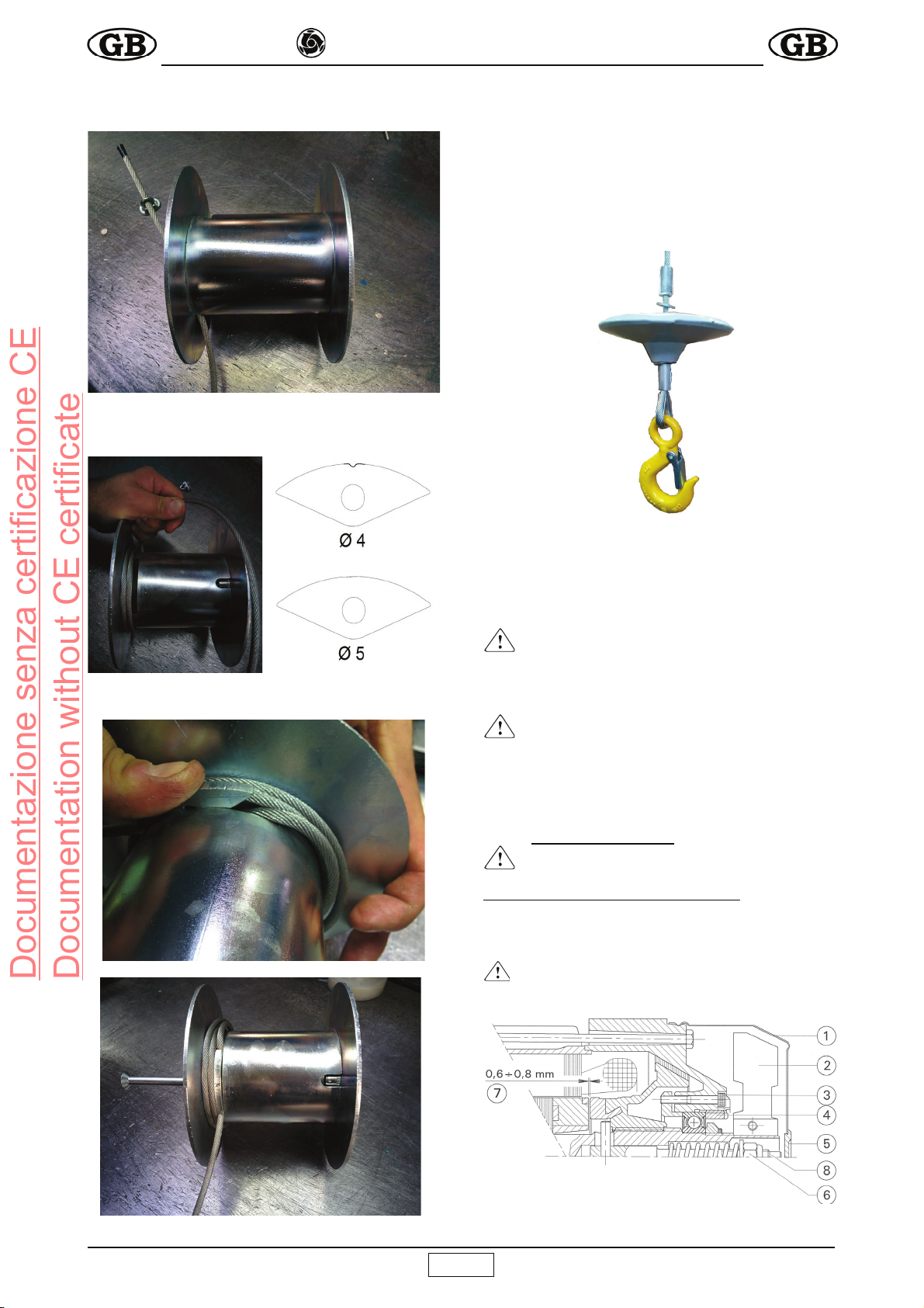
1) Das Seil durch Betätigen der Abwärtstaste leer bis zum unteren
Ladebereich absenken und prüfen, ob am Endanschlag mindestens
drei Wicklungen auf der Trommel verblieben sind.
2) Leerzyklus-Probe(LQHNJVFKZHUH3UÀDVWDXIGHP6HLODXI]XJ
anbringen und den einwandfreien Betrieb durch Ausführung eines
kompletten Auf- und Abwärtslaufs überprüfen.
Aufwärts-, Abwärts- und der Stopp-Taste, das Auslösen des oberen
Endschalters und das korrekte Aufwickeln des Kabels auf der
Trommel, sowie das Auslösen der Motorbremse ausprobieren.
3) Belastungsprobe. Dieser Test ist mit der für den Seilaufzug
maximal vorgesehenen Last auszuführen. Einen komplettenAufwärts-
und Abwärtslauf ausführen, um die Verankerungen des Seilaufzugs
und der Bremsvorrichtung des Elektromotors zu kontrollieren.
Nach dem Test ist festzustellen, ob die Tragkonstruktionen
nachgegeben haben oder Setzungen zu verzeichnen sind. Hierzu die
horizontale Ausrichtung der Trommel nachprüfen (unter Verwendung
einer Wasserwaage, siehe Abb.1).
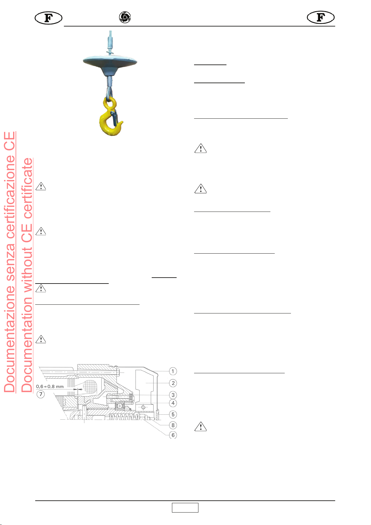
4) Der Seilaufzug ist mit einer Sicherheitsvorrichtung ausgestattet,
welche den Hub der Maschine am höchsten Punkt (Bez.9) anhält.
(V HPS¿HKOW VLFK MHGRFK GHUHQ$XVO|VHQ GXUFK UHFKW]HLWLJHV
Loslassen der entsprechenden Taste und folgliches Anhalten der
Maschine zu vermeiden.
Wenn das Seil vollkommen abgewickelt ist, muss die in der Nähe
GHU0DVFKLQHEH¿QGOLFKH%HGLHQXQJVSHUVRQGDUDXIDFKWHQGDVV
die Wicklungsrichtung an der Trommel nicht umgekehrt wird.
Nach Abschluss der Probe muss das Datum, die Prüfung
der Installation, komplett mit Unterschrift und eventuellen
Anmerkungen in das Prüfungsprotokoll (Tab.2) eingetragen
werden.
Das beschriebene Prüfverfahren, komplett mit
Leerzyklus-Probe 2) und Belastungsprobe 3) muss bei jeder
neuen Installation der Maschine durchgeführt werden.
6. GEBRAUCHS- UND SICHERHEITSHINWEISE
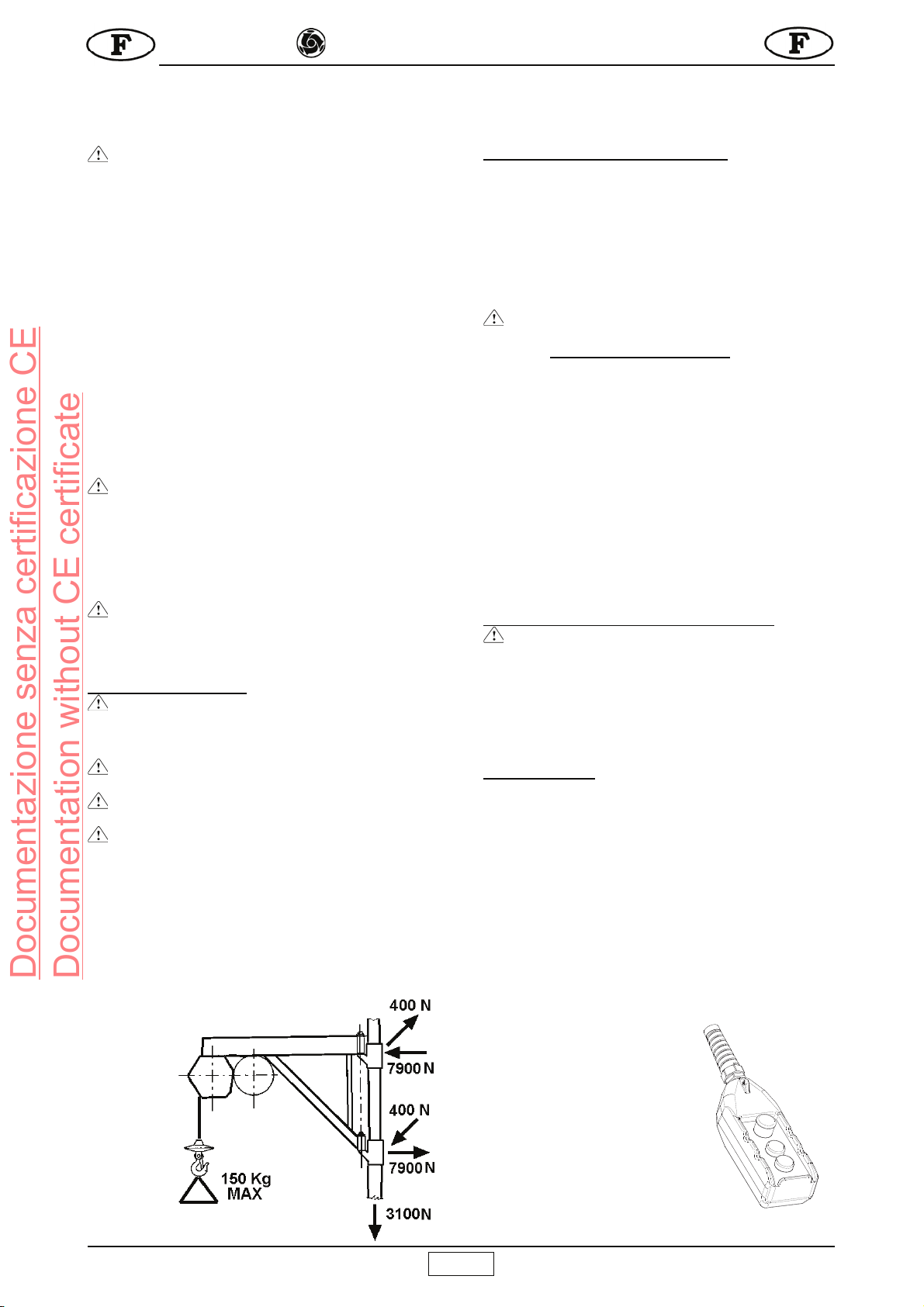
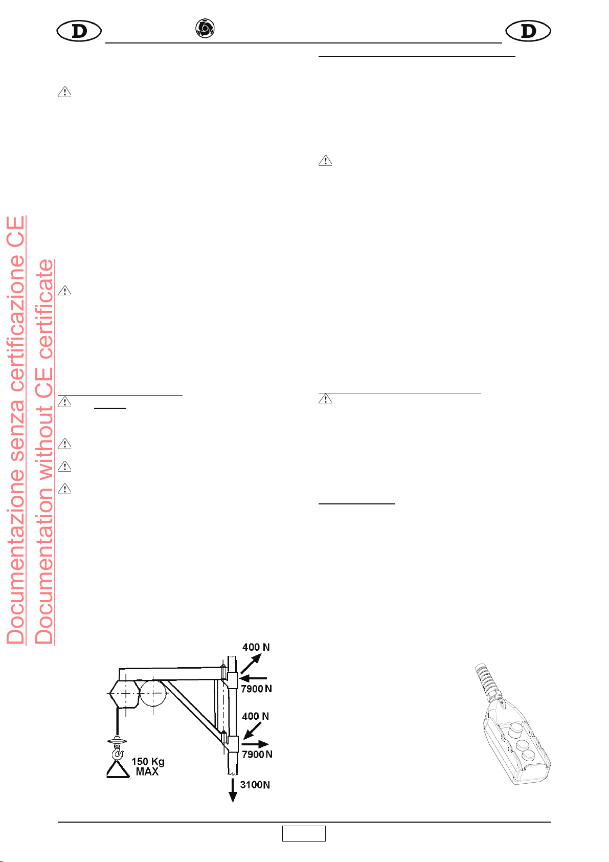
- 1)Auf keinen Fall Lasten heben, welche die Tragfähigkeit
des Seilaufzugs überschreiten.
- 2) Sicherstellen, dass sich unter der schwebenden Last
keine Personen aufhalten.
- 3) Nicht versuchen am Boden verankerte Lasten (z.B.
Pfosten, Plinthen, usw.) zu heben.
- 4) Sicherstellen, dass die Last sicher am Haken des
Seilaufzugs befestigt ist und stets die Sicherung schließen.
- 5) Falls für das Einhängen der Last irgendwelches
Zubehör (Riemen, Seile, Gurte, usw.) erforderlich ist, muss
dieses geprüft und bescheinigt sein; das Gewicht dieser
Zubehörteile muss von der Höchstraglast abgezogen werden.
- 6) Während der Hubfahrt dürfen keine Lastteile hervorstehen.
- 7) Vor dem Lösen der Last muss sichergestellt werden,
REVLHVWDELODXÀLHJW
- 8) Hängende Lasten dürfen weder ruckartig gelöst
werden noch darf zum Abladen einer Last die Verzurrung
aufgeschnitten werden, da dies eine elastische Gegenreaktion
auf die gesamte Struktur bewirkt.
- 9) Während des Betriebs nicht die Hände oder andere
Körperteile in die Nähe der Trommel bringen, weil diese sich
sonst am aufwickelnden Seil verfangen könnten, wodurch
schwerwiegende Verletzungen hervorgerufen werden können.
- 10) Während des Betriebs nicht die Hände oder andere
Körperteile in die Nähe des Gegengewichtes bringen, weil
diese sonst am Hebel des Endschalters eingeklemmt werden
können.
- 11) Die Maschine nicht bei ungünstigen
Wetterverhältnissen (Wind oder Gewitter) gebrauchen, weil
die Last in einem solchen Fall nicht ausreichend geführt
wird. Die maximale Windgeschwindigkeit sollte 12,5 m/s
nicht überschreiten.
- 12) Die Bedienungsposition und die Beleuchtung muss auf
dem gesamten Arbeitshub die freie Sicht auf die Last ermöglichen.
- 13) Sicherstellen, dass alle Schutzvorrichtungen an
korrekt angebracht sind.
- 14) Während des Gebrauchs kontrollieren, ob sich das
Kabel korrekt Windung an Windung und ohne Lockerungen
oder Überlagerungen aufwickelt, welche das Kabel selbst
beschädigen könnten. Das Kabel in diesem Fall wieder
abwickeln, gespannt halten und korrekt aufwickeln.
- 15) Sicherstellen, dass der Arbeitshub auf der
gesamten Länge frei von Behinderungen ist und dafür Sorge
tragen, dass sich niemand aus den dazwischen liegenden
Stockwerken hinauslehnen kann.
- 16) Den unteren Ladebereich abgrenzen, damit sich
während des Hebens keine Personen dort aufhalten können.
- 17) Kinder vom Seilaufzug fernhalten.
- 18) Solange der Seilaufzug nicht gebraucht wird, muss
unbedingt vermieden werden, dass sie andere Personen
benutzen können.
- 19) Der Einsatz des Seilaufzugs für schräge
Förderbewegungen (mehr als 5° im Vergleich zur Senkrechten)
ist verboten.
- 20) Der Seilaufzug darf auf keinen Fall durch Ziehen
an der Druckknopftafel auf den Zapfen geschwenkt werden,
hierzu muss stets die Tragkonstruktion manuell gedreht
werden.
- 21) Schwebende Lasten nicht unbeaufsichtigt lassen,
sondern heben oder absenken und abladen.
- 22) Während des Hebens und Senkens die Last nicht
drehen lassen, weil sonst das Seil brechen könnte.
- 23) Bevor der Seilaufzug unbeaufsichtigt gelassen wird,
die Last abnehmen, das Seil ganz auf die Trommel aufwickeln
und den Stecker aus der Steckdose nehmen.
- 24) Beim Heben und Senken einer Last stets vorsichtig
vorgehen, abrupte Bewegungssteuerungen vermeiden, um
gefährliche horizontale und vertikale Schwingungen auf ein
Minimum zu beschränken.
- 25) Den Seilaufzug vor Regen schützen.
Vor jeder erneuten Inbetriebnahme nach einem längeren Stillstand
(beispielsweise bei Arbeitsbeginn am Morgen) muss der Lastenaufzug
durch Ausführung eines Leerzyklus geprüft werden (vgl. Anleitungen
unter Punkt 2, Kap. 5).
7. PRÜFUNGEN UND WARTUNG
Achtung! Alle Wartungsarbeiten müssen bei
stillstehender Maschine, abgehängter Stromversorgung und
ohne Last erfolgen.
- Reparaturen müssen von Fachpersonal oder in den IMER-
Kundendienst-Zentren ausgeführt werden.
- Verwenden Sie ausschließlich Original-Ersatzteile.
Documentazione senza certificazione CE
Documentation without CE certificate

19
IMER INTERNATIONAL S.p.A.
ET 150 N
Alle 6-7 Tage die Leistungsfähigkeit der Bremse des
E-Motors prüfen.
Alle Aufschriften und Schilder an der Maschine stets
perfekt leserlich halten.
Schmutzablagerungen auf der Maschine müssen
regelmäßig entfernt werden.
'LH)XQNWLRQGHU(QGVFKDOWHUIU+XEVWHWVHI¿]LHQW
halten und vor jeder Arbeitsschicht kontrollieren.
Vor jedem Einsatz der Maschine systematisch den
Zustand des Stromkabels untersuchen, das in der Zwischenzeit
unwissentlich und/oder unbewusst beschädigt worden sein könnte.
7.1 STAHLSEIL
Verwenden Sie ausschließlich neue Seile mit beiliegender
Konformitätserklärung des Herstellers, in der alle nachstehend
aufgelisteten Merkmale und die Übereinstimmung mit den
Anforderungen der UNI EN 12385-4 bestätigt werden. Diese
Merkmale entsprechen den Mindestanforderungen an die Seile:
Es können Stahlseile mit höheren Werten verwendet werden, mit
Ausnahme des Außendurchmessers, der auf jeden Fall 4 mm
betragen muss.
- Außendurchmesser 4 mm
- Zusammensetzung 133 drehgesicherte Drähte
- Gleichschlag rechts
)HVWLJNHLW(OHPHQWlUGUDKW 1PP2
- Vorgeformt Ja
- Min. Bruchbelastung 10,2 kN
- Länge 41 m
2EHUÀlFKHQEHKDQGOXQJ JHIHWWHW
- Der IMER-Bestellcode ist in der Ersatzteil-Tabelle aufgeführt.
7.1.1 AUSTAUSCH DES STAHLSEILS
Diese Arbeit darf nur von einer autorisierten Kundendienststelle
IMER International ausgeführt werden.
Den Haken (Bez. 2, Abb. 1) ausbauen und das Gegengewicht
abziehen.
Die Trommel ist mit einer Vorrichtung ausgestattet, die dafür
sorgt, dass auch bei vollkommen abgewickeltem Seil stets zwei
ganze Seilwindungen aufgewickelt bleiben.
1) Das Seil vollkommen abwickeln.
2) Das Seil durch die Bohrung und die Öse aus dem
Trommelinnern herausziehen.
3) Das neue Seil in die Bohrung einführen und durch die Öse
auf der Seite der Trommel ziehen (Abb. 4.1).
Abb. 4.1
4) Die Klemme am Ende festziehen und dabei zirka 1 cm Seil
freilassen; danach das Seil ziehen, bis die Klemme an der
Innenwand der Trommel anliegt.
5) Zwei vollständige Seilwindungen enganliegend auf die
Trommel aufwickeln (Abb. 4.2).
6) Eine für das eingesetzte Seil geeignete Kabelklemme
verwenden (Abb. 4.3)
Abb. 4.2 Abb. 4.3
7) Bei der dritten Windung das Seil über die Öse in der
Trommel führen und mit der Kabelklemme in das Innere
drücken (Abb. 4.4).
Abb. 4.4
8) Dann die Schraube durch die Seite der Trommel und die
Kabelklemme führen und im Gewindeeinsatz am anderen Ende
festschrauben. (Abb. 4.5).
Abb. 4.5
9) Das Seil anziehen, bis es fest auf dem ganzen Zylinder
anliegt.
10) Das Seil Windung an Windung in aufeinanderfolgenden
Lagen korrekt aufwickeln.
11)Das Stahlseil durch das Gegengewicht und die
Aluminiumklemme führen.
12)Die Seilkausche durch die Hakenbohrung führen.
13)Das Seil erneut durch die Klemme führen und die Kausche
in der entstandenen Schlinge festziehen.
14)Das Seil ziehen, bis alle Komponenten untereinander
angezogen sind. Anschließend die Aluminiumklemme mit einer
Presse oder einem anderen Werkzeug zusammendrücken.
(Abb. 4.6)
15) Kontrollieren, ob der obere Enschalter anspricht, wenn das
Gegengewicht gegen den Hebel stößt.
16) Die in Absatz 5 beschriebene Belastungsprobe durchführen
und den erfolgten Seilwechsel in der TAB.2 eintragen
Documentazione senza certificazione CE
Documentation without CE certificate

20
IMER INTERNATIONAL S.p.A.
ET 150 N
Abb. 4.6
7.1.2 REGELMÄSSIGE KONTROLLEN
- Täglich und jedesmal wenn anomale Belastungen
auftreten (Verdrillungen, starkes Sperren der Windungen,
Knicke oder Abrieb) eine Sichtkontrolle des Seils durchführen.
Im Falle der in der Abb.14 aufgeführten Mängel muß das Seil
ersetzt werden.
- Tages- und vor dem Aufzug mit steuern die richtige
Gegengewicht zu der Verhaftung des Top-Spot und darf nicht
aufgrund einer Verformung oder Abnutzung des Hebels des
Endschalter gestoppt werden.
Alle drei Monate muß das gesamte Seil, und zwar besonders
die Enden, sorgfältig kontrolliert werden. Das Prüfergebnis ist in
das Formular des Anleitungsheftes Tab.2 einzutragen, das vom
Baustellenleiter verwahrt werden muß.
-
Das Seil mindestens einmal pro Jahr erneuern.
(,167(//81*'(502725%5(06($EE
Die Bremse des Elektromotors spricht bei Ausfall der Motorstrom-
versorgung an.
Falls sich die Bremskraft verringern sollte, muss die Vorrichtung
vom zuständigen Wartungstechniker kontrolliert und bei Bedarf
reguliert werden.
-
Achtung! Vor Eingriffen an der Bremse stets sicher-
stellen, dass die Last abgenommen, der Netzstecker gezogen
und der Motor kalt ist.
Abb. 5
7.2.1. Einstellung der Bremse
Den Verschluss 5 der Lüfterradabdeckung 1 entfernen.
Steigerung der Bremswirkung: Die selbstsichernde Mutter 6
langsam gegen den Uhrzeigersinn drehen und prüfen, ob die
Bremse während der Senkfahrt ausgelöst wird.
Reduzierung der Bremswirkung: Mutter 6 im Uhrzeigersinn drehen.
7.2.2. Regulierung des Spalts
Falls die Bremse blockiert oder abgenutzt ist, muss der Spalt
folgendermaßen eingestellt werden.
Die Lüfterabdeckung 1 abnehmen und den Lüfter 2 demontieren.
Die drei Inbusschrauben 3 lockern.
Bremse blockiert: Nut 4 im Uhrzeigersinn drehen, um den Spalt
7 zu vergrößern und die Bremse zu entsperren (Abstand 0,6-0,8
mm).
Bremse abgenutzt: Nut 4 gegen den Uhrzeigersinn drehen, um
den Spalt zu verkleinern (Abstand 0,6-0,8 mm).
Die drei Inbusschrauben 3 vorschriftsmäßig arretieren und Lüfter
samt Abdeckung montieren.
Die Bremswirkung nach ausgeführter Einstellung mehrmals mit
voller Last prüfen.
7.3 SCHMIEREN DES GETRIEBEMOTORS
- Der Getriebemotor darf kein Öl verlieren. Auffällige Ölverluste
können auf Beschädigungen der Aluminium-Struktur hinweisen.
In diesem Fall muß das Gehäuse sofort abgedichtet oder gewe-
chselt werden.
-
Vor jedem Gebrauch über das Schauglas den Ölstand
des Getriebemotors kontrollieren und eventuell auffüllen. Das
Öl muß zirka alle 2000 Betriebsstunden gewechselt werden.
Verwenden Sie zu diesem Zweck Getriebeöl mit Viskosität
VG 460 bei 40C (SAE 90-140)..
-
Altöl ist Sondermüll, der vorschriftsmäßig entsorgt
werden muß.
7.4 ELEKTRIK
Die Unversehrtheit der isolierenden Hülle des Bedienfeldes kon-
trollieren und diese im Falle der mangelhaften Dichtigkeit durch ein
IMER Original-Ersatzteil ersetzen. Sicherstellen, daß die Stahllitze,
die das Bedienfeld mit der Schalttafel verbindet, kürzer als das
Stromkabel ist, damit dieses nicht gezogen wird.
8. DEMONTAGE DER SEILWINDE
Jede Art von Last vom Haken der Seilwinde nehmen.
Das Metallseil vollkommen auf die Trommel aufwickeln. Die
Stromversorgung abhängen.
Den Splint am Haltezapfen entfernen und die schwenkbare Tra-
gestruktur ausbauen.
Bei Verwendung von Brücken den Hubwagen zunächst aus den
Führungen nehmen, von der Seilwinde ausbauen und erst dann
die Ballaste abnehmen..
9. TRANSPORT UND STILLEGUNG
- Lassen Sie die installierte Seilwinde niemals unbeaufsichtigt
stehen, ohne zuvor die Stromversorgung abzuhängen und das
Seil ganz auf die Trommel aufzuwickeln.
Falls die Maschine längere Zeit eingelagert werden soll, muß sie
XQEHGLQJWJHJHQ:LWWHUXQJVHLQÀVVHJHVFKW]WZHUGHQ
- Während dem Transport müssen die verschiedenen Maschi-
nenteile gegen Stöße und Einklemmen geschützt werden, weil
sonst die Funktionalität und die mechanische Festigkeit gefährdet
werden.
10. VERSCHROTTEN DER SEILWINDE
Bei der Verschrottung der einmal ausrangierten Seilwinde sollten
wenigstens die folgenden Phasen eingehalten werden:
a) das Öl über den speziellen Stopfen ablassen;
b) Die verschiedenen Plastikteile und Elektrokomponenten (Kabel,
Bedienfeld, usw.) trennen;
c) die Metallkomponenten nach Art des Metalls sortieren (Stahl,
Aluminium, usw.).
Die auf diese Weise sortierten Teile vorschriftsmäßig entsorgen.
- Die Komponenten nicht unkontrolliert wegwerfen, da
sie sich entzünden können und die Umwelt belasten.
11. STÖRUNGEN/URSACHEN/ABHILFEN
STÖRUNGEN URSACHEN ABHILFEN
Maschine
reagiert nicht auf
die Betätigung
der Bedientasten
(Heben –
Senken).
Not-Aus-Schalter
gedrückt.
Schalter
durch Drehen
deaktivieren.
Maschine nicht
unter Spannung.
Versorgungslei-
tung überprüfen.
Netzstecker nicht
ordnungsgemäß
angeschlossen.
Netzstecker
ordnungsgemäß
an der Steckdose
anschließen.
Schutzschalter
des externen
Schaltkastens
ausgelöst.
Schutzschalter
wieder
einschalten.
Documentazione senza certificazione CE
Documentation without CE certificate
This manual suits for next models
2
Table of contents
Languages:
Other IMER Lifting System manuals
Popular Lifting System manuals by other brands

Sigma
Sigma Far Tools One EP 400 Original manual translation

Sirio Antenne
Sirio Antenne SRS1351 - I user manual

Vestil
Vestil A-LIFT-R instruction manual

Arjo
Arjo Maxi 500 Quick reference guide

WOOD'S POWR-GRIP
WOOD'S POWR-GRIP MRTALPR4FS625DC instructions

HESHBON
HESHBON HL-26K Installation, operation and maintenance manual