Part No. 360178 Form No. F121203A
Page 2 of 12
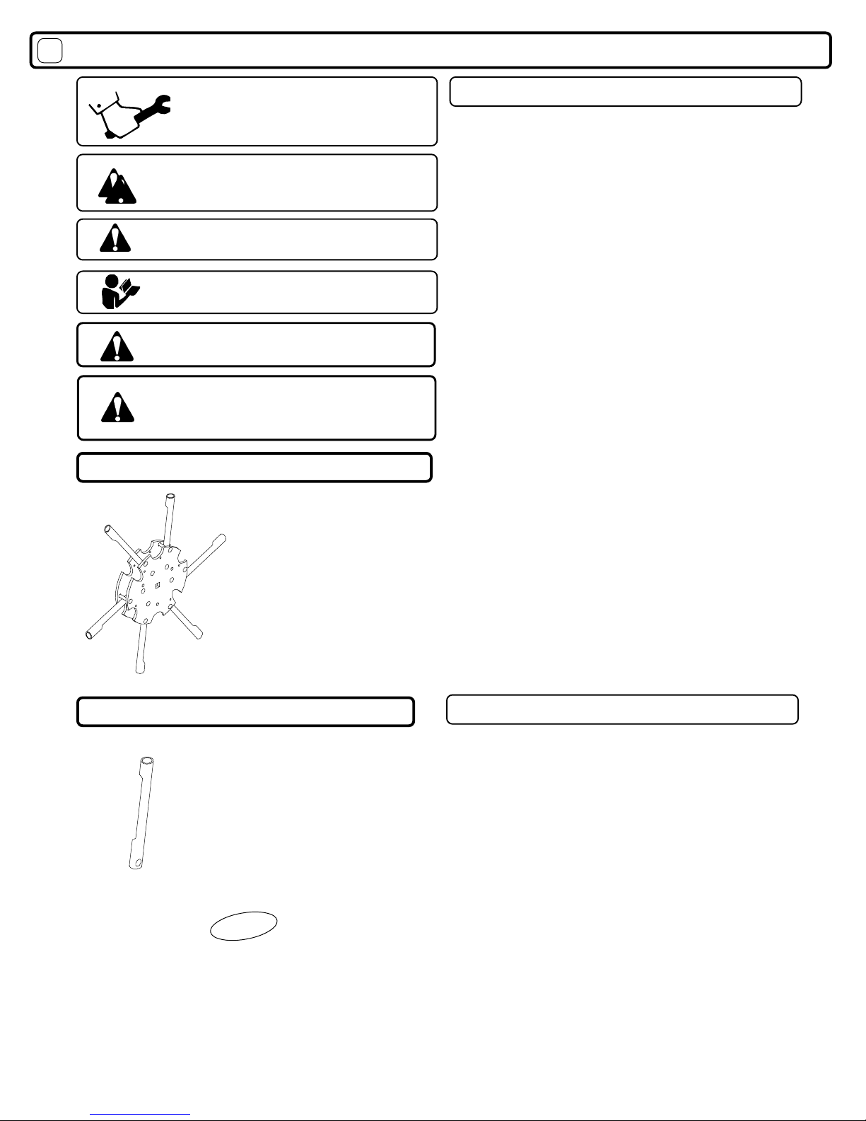
IN THE INTEREST O SA ETY
THIS SYMBOL MEANS WARNING OR CAUTION. DEATH, PERSONAL INJURY AND/OR PROPERTY
DAMAGE MAY OCCUR UNLESS INSTRUCTIONS ARE OLLOWED CARE ULLY.
BE ORE STARTING ENGINE, READ AND UNDERSTAND THE “ENTIRE OPERATOR'S MANUAL &
ENGINE MANUAL.”
WARNING: DO NOT
1. DO NOT run engine in an enclosed area.
Ex aust gases contain carbon monoxide, an
odorless and deadly poison.
2. DO NOT place ands or feet near moving
or rotating parts.
3. DO NOT store, spill or use gasoline near
an open flame, or devices suc as a stove,
furnace, or water eater w ic use a pilot
lig t or devices w ic can create a spark.
4. DO NOT refuel indoors w ere area is not
well ventilated. Outdoor refueling is recom-
mended.
5. DO NOT fill fuel tank w ile engine is
running. Allow engine to cool for 2 minutes
before refueling. Store fuel in approved
safety containers.
6. DO NOT remove fuel tank cap w ile
engine is running.
7. DO NOT operate engine w en smell of
gasoline is present or ot er explosive
conditions exist.
8. DO NOT operate engine if gasoline is
spilled. Move mac ine away from t e spill
and avoid creating any ignition until t e
gasoline as evaporated.
9. DO NOT transport unit wit fuel in tank.
10. DO NOT smoke w en filling fuel tank.
11. DO NOT c oke carburetor to stop
engine. W enever possible, gradually
reduce engine speed before stopping.
12. DO NOT run engine at excessive
speeds. T is may result in injury & /or
damage to unit.
13. DO NOT tamper wit governor springs,
governor links or ot er parts w ic may
c ange t e governed engine speed.
14. DO NOT tamper wit t e engine speed
selected by t e engine manufacturer.
15. DO NOT c eck for spark wit spark plug
or spark plug wire removed. Use an
approved tester.
16. DO NOT crank engine wit spark plug
removed. If engine is flooded, place t rottle
in “FAST” position and crank until engine
starts.
17. DO NOT strike flyw eel wit a ard
object or metal tool as t is may cause
flyw eel to s atter in operation. Use proper
tools to service engine.
18. DO NOT operate engine wit out a
muffler. Inspect periodically and replace, if
necessary. If engine is equipped wit
muffler deflector, inspect periodically and
replace, if necessary, wit correct deflector.
19. DO NOT operate engine wit an
accumulation of grass, leaves, dirt or ot er
combustible material in t e muffler area.
20. DO NOT use t is engine on any forest
covered, brus covered, or grass covered
unimproved land unless a spark arrester is
installed on t e muffler. T e arrester must
be maintained in effective working order by
t e operator. In t e State of California t e
above is required by law (Section 4442 of
t e California Public Resources Code).
Ot er states may ave similar laws. Federal
laws apply on federal lands.
21. DO NOT touc ot muffler, cylinder, or
fins because contact may cause burns.
22. DO NOT run engine wit out air cleaner
or air cleaner cover.
23. DO NOT operate during excessive
vibration!
24. DO NOT leave mac ine unattended
w ile in operation.
25. DO NOT park mac ine on a steep grade
or slope.
WARNING: DO
1. ALWAY DO remove t e wire from t e
spark plug w en servicing t e engine or
equipment TO PREVENT ACCIDENTAL
STARTING.
2. DO keep cylinder fins and governor
parts free of grass and ot er debris
w ic can affect engine speed.
3. DO pull starter cord slowly until resis-
tance is felt. T en pull cord rapidly to avoid
kickback and prevent and or arm injury.
4. DO examine muffler periodically to be
sure it is functioning effectively. A worn or
leaking muffler s ould be repaired or
replaced as necessary.
5. DO use fres gasoline. Stale fuel can
gum carburetor and cause leakage.
6. DO c eck fuel lines and fittings frequently
for cracks or leaks. Replace if necessary
7. Follow engine manufacturer operating
and maintenance instructions.
8. Inspect mac ine and work area before
starting unit.
VIBRATION
SOUND TESTS VIBRATION LEVELS 3.6 g max.
Vibration levels at t e operators andles were
measured in t e vertical, lateral, and longitudinal
directions using calibrated vibration test equipment.
Tests were performed on 02/06/2002 under t e
conditions listed:
WIND DIRECTION:
HUMIDITY:
TEMPERATURE:
BAROMETRIC PRESSURE:
GENERAL CONDITION:
OUND
Sound tests conducted were in accordance
wit 2000/14/EEC and were performed on
02/05/2002 under t e conditions listed:
GENERAL CONDITION:
WIND SPEED:
WIND DIRECTION:
HUMIDITY:
TEMPERATURE:
BAROMETRIC PRESSURE:
30.29" Hg (769 mm Hg)
53 %
Nort East
3.5 MPH (5.6 km )
42 F (6 C)
Cloudy
30.13" Hg (765 mm Hg)
90 %
Nort East
5 MPH (8 km )
37 F (3 C)
Cloudy
5
6
8
7
○○○○○○
AFETY IN TRUCTION
GENERAL AFETY
A EMBLY
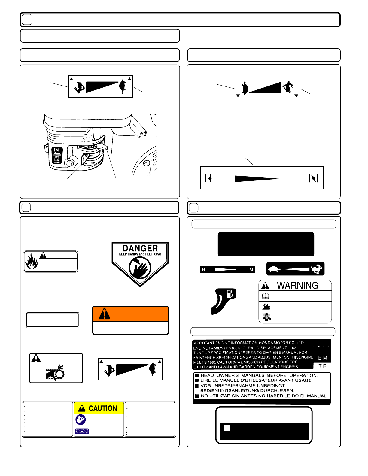
CONTROL
LABEL
OPERATION
MAINTENANCE
PART DRAWING & LI T...
TROUBLE HOOTING
WARRANTY PROCEDURE
○○○
○○ ○○○○○
○○○○○○○○
○○○○○○○○
○○○○○
○○
10-11
12
12
6 - 7
4
4
3
3
2
TABLE O CONTENTS
8 - 9
WARNING: T e Engine Ex aust from t is product contains c emicals known
to t e State of California to cause cancer, birt defects or ot er reproductive arm.
○○○○○○○○
101 dB