1. Disconnect spark plug wire.
2. Loosen four screws (112) holding belt cover (10) and remove the cover.
3. Examine condition of belt. Look for cracks, splits, delamination or damage to outer covering. Any of these things might
warrant replacement.
4. If the idler is not providing enough tension inspect the clutch cable spring (item 231) underneath the handle.This spring
body should stretch to a length of 1.75” when the operator presence handle is actuated. If not enough tension is being
put on the spring this could mean a stretched belt, but most likely the cable needs adjusted. Simply loosen the jam nuts
holding the cable on the handle assembly and adjust the cable either in or out to shorten or lengthen the spring. Re-
tighten nuts and check spring stretch.
7. Replace belt cover (10) and secure with screws removed earlier.
8. Reconnect spark plug wire.
9. Check belt tension by operating unit under conditions that caused belt slippage. If belt continues to slip it may require
replacement before operation may continue.
CHAIN REPLACEMENT
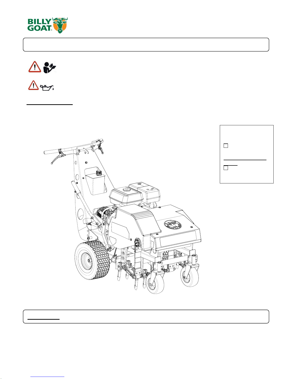
1. Remove the hood (item 4) by removing the seven bolts, washers, and lock washers. (items 111,119,128), that
secure it to the tining frame.
2. Locate the bolt (item 31, 33) and nut (item 80) that hold each chain idler sprocket to the tining frame of the unit. One
idler sprocket sets tension on the left tine drive chain and one sets tension on the right tine drive chain.
3. Loosen the bolt and nut and slide the idler sprocket (item 29) to the bottom of the slot in the bracket.
4. Locate the master link in the chain and remove.
5. When installing new chain make sure that the inner crank arm is lined up with the inner crank arm of the opposite
side. In operation, the two inner tining arms move together and the two outer tining arms move together. Any other
timing of the arms will result in unsatisfactory performance of the machine.
6. Once new chain is installed,
7. Replace the hood and reinstall the seven bolts, washers, and lock washers that secure it in place.
NOTE: Over tensioning the chain will cause premature chain and sprocket wear. DO NOT OVER TENSION THE CHAIN. A
properly tensioned chain will have slack of 3/8"-1/2" when moved by hand.
LUBRICATION
CHAINS-
1. Remove the top guard by removing the four nuts, two on each side that secures it to the frame.
2. Apply a light coat of No. 30 Oil or a penetrating chain lubricant to keep the chain clean and in good running order.
3. Replace the guard and reinstall the four screws that secure it in place.
NOTE: If machine is cleaned with a pressure washer the chains should be lubricated after each cleaning.