bily Retractable Safety Gate User manual

BG37XXXX_IM_R4 (Dec 2018)
Please Note: Instructional images may vary
in style from the product you purchased.
English
Retractable
Safety Gate
ELFE JUVENILE PRODUCTS
2520 MARIE-CURIE
SAINT-LAURENT
(QC) H4S 1N1
service@elfe.ca
www.elfe.com
1-800-667-8184

Failure to follow these warnings and the assembly instructions could result in serious injury or death.
1. Install according to manufacturer’s instructions.
2. This gate is suitable for openings up to 140 cm (55”).
3. This gate is NOT suitable for openings wider than 140 cm (55”).
4. Use only with the locking/latching mechanism securely engaged on side away from child.
5. This product is intended for use with children from 6 – 24 months.
6. Never leave child unattended. This product will not necessarily prevent all accidents.
7. Never use with a child who is able to open or climb over the gate.
8. WARNING: Incorrect fitting or positioning of this safety barrier can be dangerous. Never let go
of handle when gate is retracting.
9. To prevent serious injury, never allow adults, children or pets to climb over or under the gate,
as it may damage this safety gate.
10. The surfaces that the safety gate is to be fixed to must be suitable for the purpose and must
be structurally sound. NOTE: Do not use this gate if it can’t be installed to walls, door frames
or posts – tightly and flatly.
11. DO NOT install this gate to hollow walls.
12. The clearance space between the Base of Casing and the floor MUST NOT exceed 0.3 cm (0.12”).
13. This safety gate must NOT be fitted across window openings and the like.
14. NOTE: Never use without Locking Hooks.
15. Securely install and operate the gate according to instructions to help prevent accidental
injury.
16. Do not use the safety gate if any components are damaged or missing.
17. Install this gate away from heaters and other sources of heat.
18. This gate must NEVER be used as a pool or pond barrier.
19. Gate is not meant to replace proper adult supervision.
20. Always check that gate is locked after closing gate.
21. If the gate is used at the bottom of the stairs to prevent the child from climbing up the stairs,
it must be placed on the lowest stair.
22. If the gate is to be used at the top of the stairs to prevent the child from falling down the
stairs, it must not be placed on any stair below the level of the top stair. At the top of the
landing, position the gate 15 cm (6”) away from the top step.
23. Spacers are required when fitting gate to skirting board.
24. This product requires adult assembly.
WARNING – The position of the safety barrier in relation to the stairs may have an
adverse effect on your child’s safety. KEEP INSTRUCTIONS FOR FUTURE USE. If you sell or
give away this product, make sure to give this instruction manual to the new owner. 2
WARNING
!
Need assistance?
Call our toll-free Consumer Relations help line at 1-800-667-8184
(Monday to Friday 8:30a.m. to 5:00p.m. - Eastern Time)
SOME ASSEMBLY REQUIRED
Gate Warnings
3
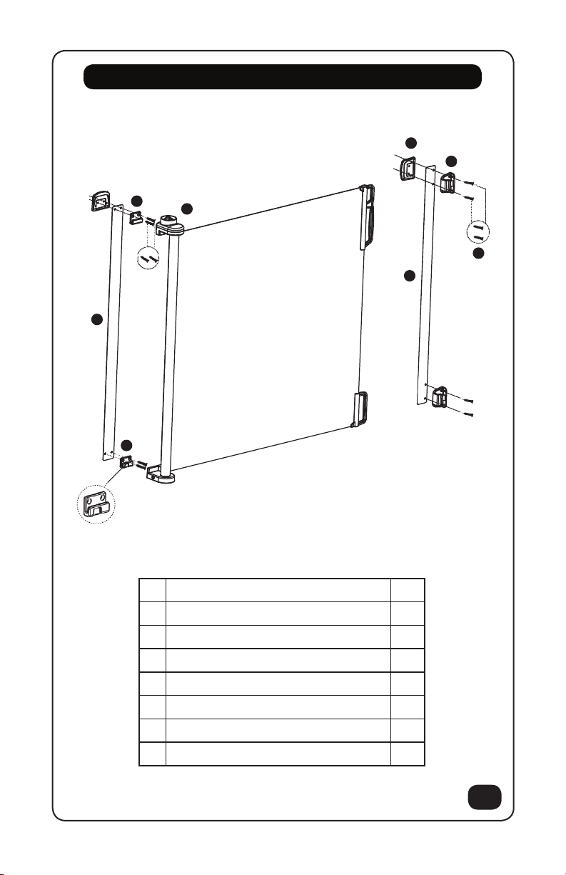
Parts List
Note: Lower gate mount has a locking groove.
Note: 2 sets of mounting brackets included for convenient relocation.
No. Parts Name (Hardware kit) Qty
A Gate Assembly 1
B Screws & Plugs 8
C Upper Gate Mount 1
D Lower Gate Mount 1
E Guide 1 template 1
F Guide 2 template 1
G Catch Mounts 2
H Wall Spacers 6
C
E
H
F
A
D
G
B
4
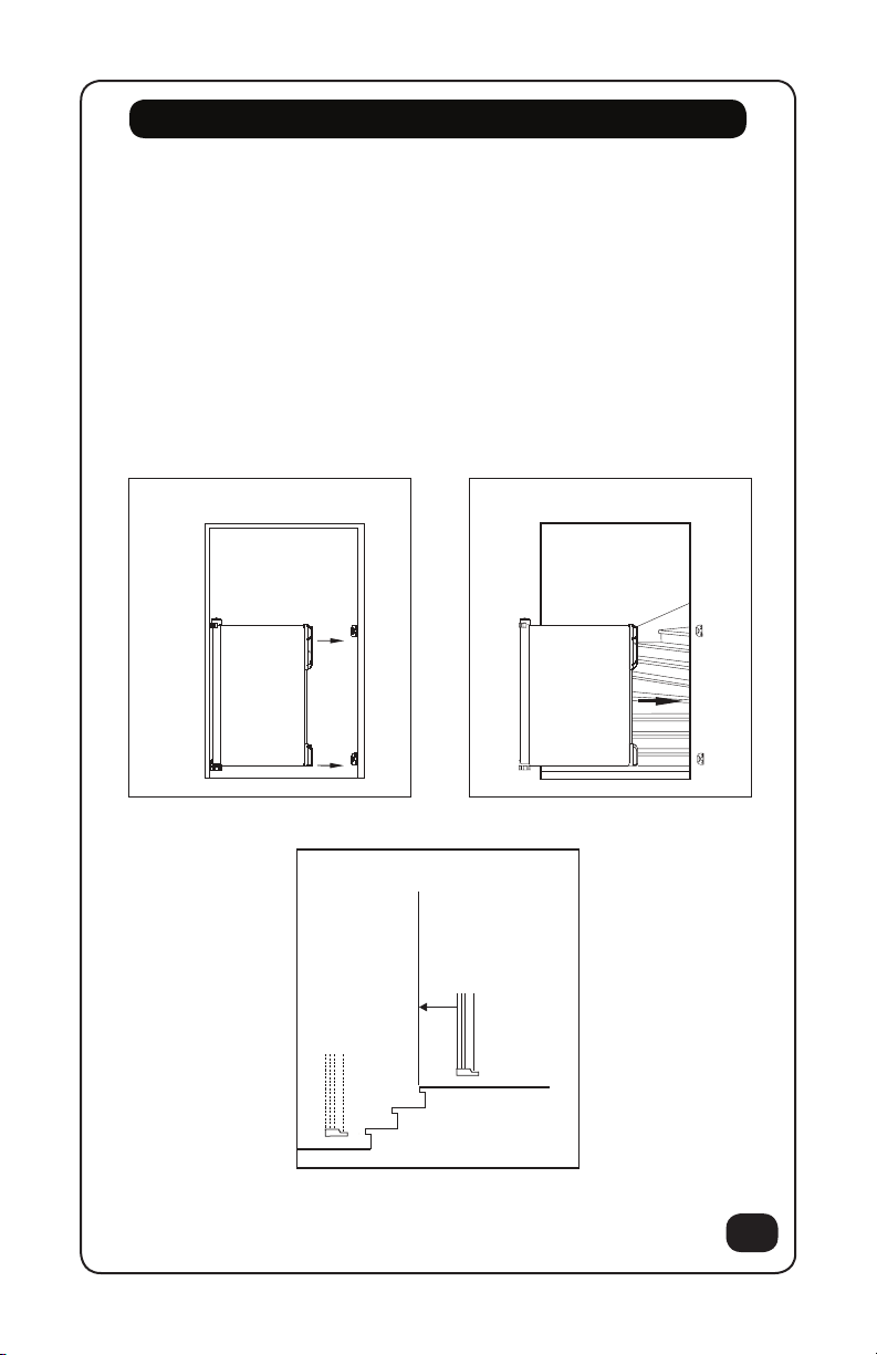
Location
The Retractable Safety Gate can be fitted either inside the opening/stairway (2-1) or on
the wall besides the opening/stairway (2-2). WARNING: the position of the safety barrier
for stairs depends on the position of the child in relation to the stair. When fitting the
Retractable Safety Gate at the top of stairs, place the gate at the top floor level, 15 cm /
6 inches from the first step (2-3). When fitting the Retractable Safety Gate at the bottom
of stairs, place the gate at the lowest stair. Always make sure that the safety barrier is in
the correct position according to the template. Before fixing the Retractable Safety Gate,
decide whether it should open left to right or vice versa, and therefore which side will be
most suitable for the handle.
2-1 2-2
2-3
15 cm
6” (po)
5
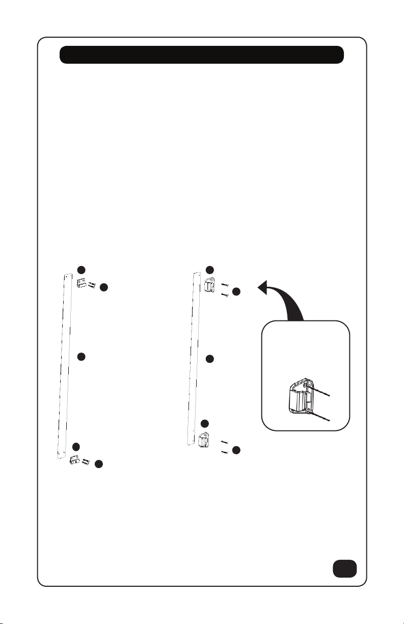
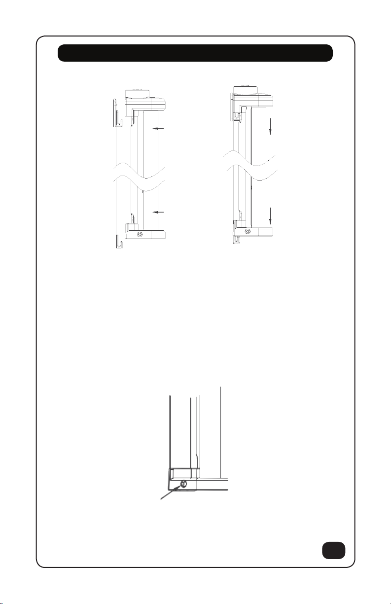
Installation Outside of Opening or Doorway
To install you will need a Phillips screwdriver, pencil, level and drill.
1. Place Guide 1 template on the surface you want the Gate Assembly to be mounted
to with the bottom of the template flush with the floor, use a level to ensure the
guide is straight. Note: leave 2 cm between guide and the edge of the opening to
ensure gate won’t overhang edge. Repeat for Guide 2 template on the opposite side
of opening.
2. Use pencil to mark the center of each hole, and then remove both Guides.
3. Drill a 3 mm pilot hole at each pencil mark for timber surfaces and for hardwall drill
a 6 mm hole and insert plugs. Note for all other surfaces use suitable fixings.
4. Align each mount in its correct position, use a Phillips screwdriver to tighten screws
till each mount is secure.
NOTE: When fixing
Catch Mounts outside
of opening. Only use
the inside countersunk
holes
EGuide 1
CUpper Gate Mount
BScrews and plugs
BB
GCatch Mount
GCatch Mount
BScrews and plugs
FGuide 2
DLower Gate Mount
6
Installation Inside Opening or Doorway
To install you will need a Phillips screwdriver, pencil, level and drill.
1. Place Guide 1 template on the surface you want the Gate Assembly to be mounted
to with the bottom of the template flush with the floor, use a level to ensure the
guide is straight. Note: leave 2 cm between guide and the edge of the opening to
ensure gate wont overhang edge. Repeat for Guide 2 template on the opposite side
of opening.
2. Use pencil to mark the center of each hole, and then remove both Guides.
3. Drill a 3 mm pilot hole at each pencil mark for timber surfaces and for hardwall drill
a 6 mm hole and insert plugs. Note for all other surfaces use suitable fixings.
4. Align each mount in its correct position, use a Phillips screwdriver to tighten screws
till each mount is secure.
NOTE: When fixing Catch Mounts only use the inside countersunk holes.
NOTE: When fixing Catch
Mounts inside of opening.
Only use the outer holes.

7
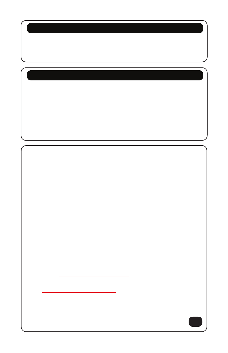
Installation (continued)
Installation with skirting/baseboard
To help correct for the offset of a skirting board or baseboard spacers will be
required. Only use spacers for the Upper Gate mount and the Upper Catch
(parts C & G). Measure the width of your skirting/baseboard and use the closest
number of spacers to fit this width.
To install you will need a Phillips screwdriver, pencil, level and drill.
1. Place Guide 1 template on the surface you want the Gate Assembly to be mounted
to with the bottom of the template flush with the floor, use a level to ensure the
guide is straight. Note: leave 2 cm between guide and the edge of the opening to
ensure gate wont overhang edge. Repeat for Guide 2 template the opposite side of
opening.
2. Use pencil to mark the center of each hole, and then remove both Guides.
3. Drill a 3 mm pilot hole at each pencil mark for timber surfaces and for hardwall drill
a 6 mm hole and insert plugs. Note for all other surfaces use suitable fixings.
4. Align each mount in its correct position, use a Phillips screwdriver to tighten screws
till each mount is secure.
Upper Gate Mount Upper Catch Mount
8
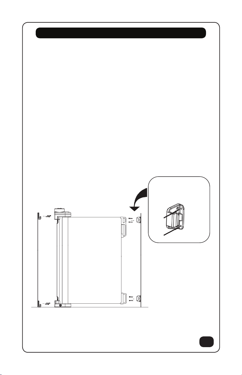
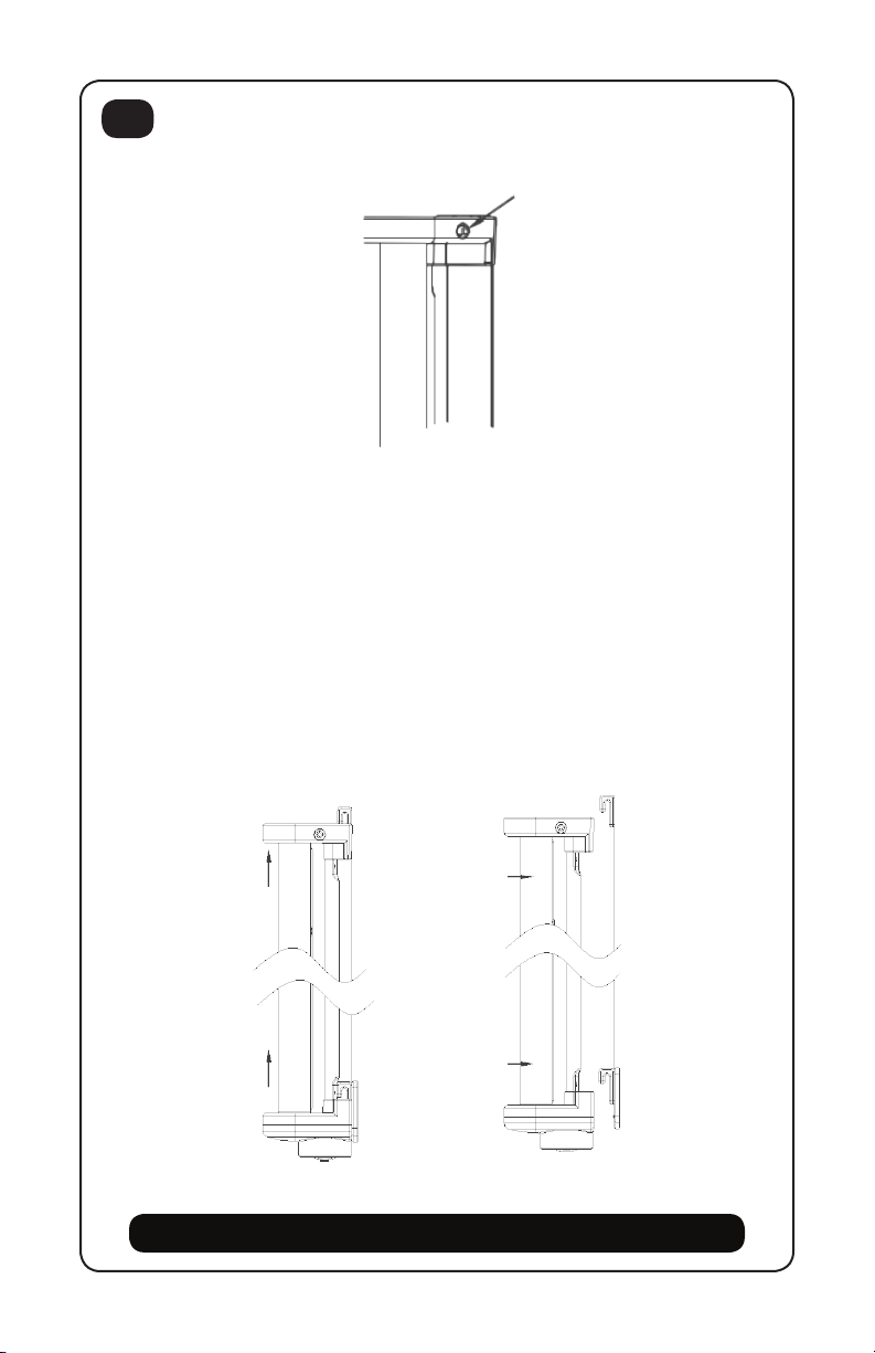
Installation (continued)
Gate Assembly
1. Attach Gate Assembly to the Gate Mounts by aligning the gate directly above the
mounts and sliding straight down over mounts.
Check that the Gate assembly is flush against the wall and is locked firmly in place.
2. To remove gate from the mounts, push and hold the lock release button while
sliding the gate upwards.
3. Locking/latching mechanism securely engaged on side away from child.
Lock Release

9
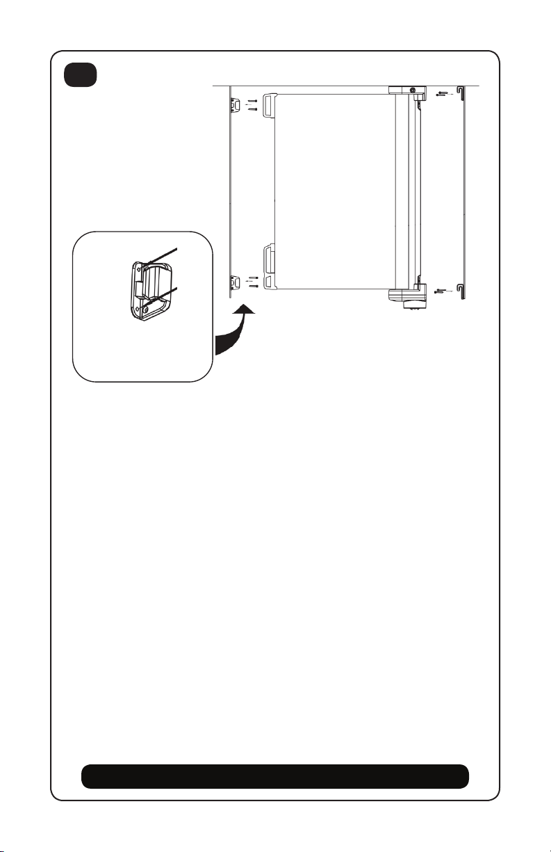
Operation
Care Instructions
To extend gate
1. To unlock the mechanism, simply push down and turn the button clockwise, at
the same time grasp the handle and pull evenly.
2. Release the button and continue pulling the handle toward the catches.
3. Hook the handle onto the catches ensuring both the top and bottom are aligned.
1. Wipe clean with damp cloth and mild soap.
2. Do not use bleach.
3. Dry with cloth.
Note: When gate is retracting always hold the handle and guide the gate evenly
back into its original position.
WARNING
!
Never let go of handle when gate is retracting.
10
Important Information:
Before you begin assembly, please read these directions. Make sure all pre-assembled parts are
tight. Store this instruction manual in a safe place, for future reference.
If a part is missing or if you have any questions, call us.
PLEASE DO NOT return product or parts to the store where they were purchased before calling us.
Please call us toll free at:
1-800-667-8184
Our service is fast, free and easier than returning the product.
Important: In order to help our customer service representatives better assist you, we require
that you complete the information below before calling:
Model Number:
Date:
Note: The label containing the Model Number and Manufacturer’s Date can be found behind
the lower gate mount.
Special Instructions
-This unit is guaranteed to meet all federal and provincial standards and will provide many years of service
provided you adhere to the guidelines provided for assembly, maintenance and operation.
-For parts or assistance, do not return to retailer where unit was purchased. Call or write Elfe Juvenile Products.
Limited Warranty
1 Year Limited Warranty
Elfe Juvenile Products will supply the original owner, without charge, any part discovered to be missing at
the time of purchase or found to be broken or defective during the 1 year warranty period.
The warranty begins on the date of purchase, as established by your purchase receipt. The model number,
date of manufacture, and the part description must be provided. The warranty does not apply to defects
caused by owner damage, product alteration, or unreasonable use. This warranty gives you specific legal
rights that may vary from province to province.

ELFE JUVENILE PRODUCTS
2520 MARIE-CURIE
SAINT-LAURENT
(QC) H4S 1N1
service@elfe.ca
www.elfe.com
1-800-667-8184

ELFE JUVENILE PRODUCTS
2520 MARIE-CURIE
SAINT-LAURENT
(QC) H4S 1N1
service@elfe.ca
www.elfe.com
1-800-667-8184

10
Renseignements importants :
Avant de commencer l’assemblage, lisez le présent livret d’instructions. Assurez-vous que les
pièces préassemblées sont solidement fixées. Rangez ce livret dans un endroit sécuritaire pour
vous y référer au besoin.
Pour toute question ou si une pièce est manquante, communiquez avec nous au numéro
ci-dessous. NE RETOURNEZ PAS le produit ou les pièces au magasin où ils ont été achetés
avant de nous téléphoner.
1-800-667-8184
Notre service est rapide et gratuit, et cette façon de procéder est plus facile que de retourner
le produit au magasin.
Important : Afin d’aider nos préposés à mieux vous répondre, veuillez noter les
renseignements ci-dessous avant de nous téléphoner :
Numéro de modèle :
Date:
Remarque : L’étiquette indiquant le numéro de modèle et la date de fabrication se
trouve à l’arrière de la monture inférieure.
Instructions spéciales
-Nous garantissons que ce produit satisfait à toutes les normes fédérales et provinciales et qu’il vous
servira pendant de nombreuses années, pourvu que vous respectiez les instructions d’assemblage,
d’entretien et d’utilisation
-Pour commander des pièces ou obtenir de l’aide, ne retournez pas le produit chez le détaillant où vous
l’avez acheté. Téléphonez ou écrivez plutôt à Elfe Juvenile Products.
Garantie limitée
Garantie limitée d’un an
Elfe Juvenile Products fournira au propriétaire original, sans frais, toute pièce manquante au moment
de l’achat ou qui se brise ou devient défectueuse pendant la période de garantie d’un an.
La garantie entre en vigueur à la date d’achat, telle qu’établie par votre reçu de caisse. Vous devez fournir
le numéro de modèle, la date de fabrication et la description des pièces. La garantie ne s’applique pas
aux défauts résultant de dommages causés par le propriétaire, d’une modification du produit ou d’un
usage abusif. Cette garantie vous confère certains droits en vertu de la loi et ceux-ci peuvent varier d’une
province à une autre.

9
Fonctionnement
Fermeture de la barrière
1. Pour déverrouiller la barrière, appuyez sur le bouton puis, en maintenant la
pression, faites-le pivoter dans le sens des aiguilles d’une montre. Tirez sur la
poignée d’un mouvement uniforme.
2. Lâchez le bouton et continuez à tirer vers les crochets du côté opposé.
3. Accrochez la barrière aux montures. Vérifiez que le haut et le bas sont bien alignés.
Remarque : Lorsque la barrière s’enroule, tenez-la toujours par la poignée et
guidez-la d’un mouvement uniforme jusqu’à sa position originale.
MISE EN GARDE
!
Ne lâchez jamais la poignée quand la barrière s’enroule.
Instructions d’entretien
1. Essuyez avec un linge humide et savon doux.
2. Ne pas utiliser de javelisant.
3. Sécher avec une serviette.
8
Installation (suite)
Assemblage de la barrière
1. Pour installer la barrière, placez la barrière directement au-dessus des montures et
descendez-la en ligne droite.
Assurez-vous que la barrière est droite tout contre le mur et solidement installée.
2. Pour détacher la barrière des montures, appuyez sur le bouton de déverrouillage
puis, en maintenant la pression, soulevez la barrière.
3. Le mécanisme de fermeture / verrouillage est solidement enclenché du côté
inaccessible à l’enfant.
Déverrouillage

7
Installation (suite)
Installation sur un mur muni d’une plinthe
Pour corriger le décalage causé par la plinthe, vous aurez besoin d’espaceurs.
N’utilisez les espaceurs que pour les montures supérieures (ordinaire et à crochet).
Mesurez la largeur de la plinthe et utilisez le nombre d’espaceurs nécessaire pour
obtenir une largeur équivalente.
Pour l’installation, vous aurez besoin d’un tournevis Phillips, d’un crayon, d’un niveau
et d’une perceuse.
1. Placez le 1er gabarit sur la surface à laquelle la barrière sera fixée. Posez la bordure
inférieure du gabarit au ras du plancher. Avec un niveau, assurez-vous que le gabarit
est droit. Remarque : Pour éviter le dépassement de la barrière, laissez un espace de
2 cm entre le gabarit et le bord de l’ouverture. Reprenez les étapes ci-dessus avec le
2egabarit pour fixer l’autre côté de la barrière.
2. Marquez au crayon le centre de chaque trou, puis enlevez les deux gabarits.
3. Sur chaque marque de crayon, percez un trou de 3 mm pour une surface en bois
ou un trou de 6 mm (dans lequel vous devez aussi insérer une cheville d’ancrage)
pour une surface en plâtre. Remarque : Pour tout autre type de surface, utilisez les
ancrages appropriés.
4. Placez chaque monture correctement, puis à l’aide d’un tournevis Phillips, serrez
chacune des vis pour solidifier les montures.
Monture supérieure Monture supérieure
à crochet
6
Installation à l’intérieur de l’ouverture ou du cadre de porte
Pour l’installation, vous aurez besoin d’un tournevis Phillips, d’un crayon, d’un niveau
et d’une perceuse.
1. Placez le 1er gabarit sur la surface à laquelle la barrière sera fixée. Posez la bordure
inférieure du gabarit au ras du plancher. Avec un niveau, assurez-vous que le gabarit
est droit. Remarque : Pour éviter le dépassement de la barrière, laissez un espace de
2 cm entre le gabarit et le bord de l’ouverture. Reprenez les étapes ci-dessus avec le
2egabarit pour fixer l’autre côté de la barrière.
2. Marquez au crayon le centre de chaque trou, puis enlevez les deux gabarits.
3. Sur chaque marque de crayon, percez un trou de 3 mm pour une surface en bois
ou un trou de 6 mm (dans lequel vous devez aussi insérer une cheville d’ancrage)
pour une surface en plâtre. Remarque : Pour tout autre type de surface, utilisez les
ancrages appropriés.
4. Placez chaque monture correctement, puis à l’aide d’un tournevis Phillips, serrez
chacune des vis pour solidifier les montures.
REMARQUE : Pour fixer les montures à crochet à l’intérieur de l’ouverture, utilisez les
trous fraisés.
REMARQUE : Pour fixer les
montures à crochet à l’intérieur
de l’ouverture, utilisez les trous
fraisés.

5
Installation à l’extérieur de l’ouverture ou du cadre de porte
Pour l’installation, vous aurez besoin d’un tournevis Phillips, d’un crayon, d’un niveau
et d’une perceuse.
1. Placez le 1er gabarit sur la surface à laquelle la barrière sera fixée. Posez la bordure
inférieure du gabarit au ras du plancher. Avec un niveau, assurez-vous que le gabarit
est droit. Remarque : Pour éviter le dépassement de la barrière, laissez un espace de
2 cm entre le gabarit et le bord de l’ouverture. Reprenez les étapes ci-dessus avec le
2egabarit pour fixer l’autre côté de la barrière.
2. Marquez au crayon le centre de chaque trou, puis enlevez les deux gabarits.
3. Sur chaque marque de crayon, percez un trou de 3 mm pour une surface en bois
ou un trou de 6 mm (dans lequel vous devez aussi insérer une cheville d’ancrage)
pour une surface en plâtre. Remarque : Pour tout autre type de surface, utilisez les
ancrages appropriés.
4. Placez chaque monture correctement, puis à l’aide d’un tournevis Phillips, serrez
chacune des vis pour solidifier les montures.
REMARQUE : Pour fixer
les montures à crochet à
l’extérieur de l’ouverture,
utilisez les trous fraisés.
EGabarit 1
CMonture supérieure
BVis et chevilles d’ancrage
BB
GMonture à crochet
GMonture
à crochet
BVis et chevilles d’ancrage
FGabarit 2
DMonture inférieure

4
La barrière rétractable peut être installée à l’intérieur de l’ouverture (2-1) ou sur le mur
à côté de l’ouverture (2-2). MISE EN GARDE : Pour bloquer l’accès à un escalier, établissez
l’emplacement de la barrière selon la position de l’enfant par rapport à l’escalier. En haut
d’un escalier, installez la barrière au même niveau que l’étage du haut et à 15 cm (6 po)
de la première marche (2 3). En bas d’un escalier, installez la barrière sur la marche la
plus basse. Vérifiez toujours que l’emplacement de la barrière correspond à celui indiqué
sur le gabarit. Avant de fixer la barrière rétractable, déterminez si vous l’ouvrirez de
gauche à droite ou vice versa et, ainsi, de quel côté ira la poignée.
Emplacement
2-1 2-2
2-3
15 cm
6” (po)

3
Liste des pièces
Remarque : La monture inférieure comprend
une encoche de verrouillage.
NoNom de la pièce (Quincaillerie) Qté
A Barrière 1
B Vis et chevilles d’ancrage 8
C Monture supérieure 1
D Monture inférieure 1
E Gabarit 1 1
F Gabarit 2 1
G Montures à crochet 2
H Espaceurs 6
C
E
H
F
A
D
G
B
Remarque: Deux jeux de fixations inclus pour déplacer la barrière aisément.
Table of contents
Other bily Indoor Furnishing manuals


