Bindicator VRF-1000 Series User manual
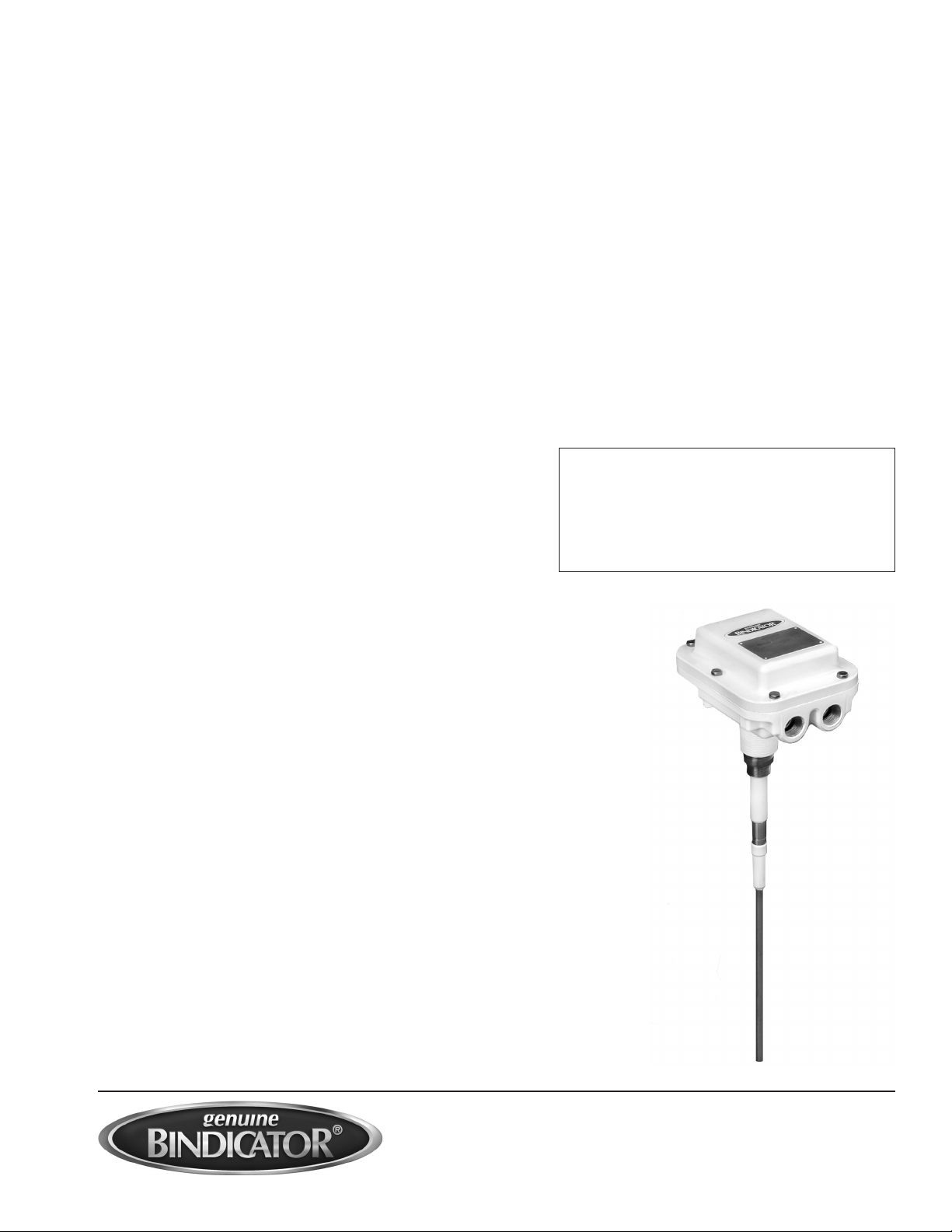
VRF-1000 Series
Integral Electronics with Opti-Sense™
Installation, Operation,
and Maintenance Manual
VRF180000
Revision G
September 2010
CAUTION
It is essential that all instructions in this
manual be followed precisely to ensure
proper operation of the equipment.

SAFETY INFORMATION
Before installing the VRF-1000, please read these instructions and be completely familiar with the
requirements and functions of the sensor.
The VRF-1000 sensor must only be installed and operated as described in this instruction manual. Note
that other actions can cause damage for which Bindicator®does not take responsibility. If the model is
not installed correctly or used in unapproved applications, dangers may arise such as product overow.
Ensure that all personnel installing, wiring, and calibrating this device are suitably qualied. All wiring
must conform to current National Electrical Code (NEC) requirements or local electrical codes. Please
be aware that any modication of the equipment may cause injury or death.
If any questions or problems arise during the installation of this equipment, please contact the
Bindicator®Applications Department at (800) 778.9242 or (864) 574.8960.

TABLE OF CONTENTS
CHAPTER 1. PRODUCT DESCRIPTION ................................................................................................ 1
Function...................................................................................................................................................... 1
Applications................................................................................................................................................ 1
Model Code Identication .......................................................................................................................... 2
Technical Specications/Approvals............................................................................................................ 3
Dimensions................................................................................................................................................. 3
CHAPTER 2. HANDLING AND STORAGE.............................................................................................. 4
Inspection and Handling ............................................................................................................................ 4
Storage....................................................................................................................................................... 4
CHAPTER 3. MECHANICAL INSTALLATION ......................................................................................... 5
Guidelines................................................................................................................................................... 5
Mounting .................................................................................................................................................... 5
CHAPTER 4. ELECTRICAL INSTALLATION ........................................................................................... 6
Guidelines................................................................................................................................................... 6
Conduit-Cable Connection................................................................................................................... 6
Input Power .......................................................................................................................................... 6
Connection Information........................................................................................................................ 6
Connection Information/Wiring Diagram.................................................................................................... 6
CHAPTER 5. SET-UP AND CALIBRATION ............................................................................................. 8
Operation.................................................................................................................................................... 8
Settings and Adjustments ........................................................................................................................... 8
Fail-Safe Selection ...................................................................................................................................... 8
High Level Fail-Safe Operation.............................................................................................................. 8
Low Level Fail-Safe Operation .............................................................................................................. 8
Sensitivity Setting.................................................................................................................................. 8
Time Delay Setting ................................................................................................................................ 8
Enable Automatic Calibration Feature................................................................................................... 9
CHAPTER 6. START-UP AND OPERATION .......................................................................................... 10
CHAPTER 7. MAINTENANCE AND SPARE PARTS LIST .................................................................... 11
CHAPTER 8. TROUBLESHOOTING...................................................................................................... 12
APPENDIX ............................................................................................................................................... 13

1
CHAPTER 1. PRODUCT DESCRIPTION
FUNCTION
The VRF-1000 is a line powered (AC or DC) material level sensor that outputs a DPDT relay contact.
The electronics and probe are integral. It is a point level sensor used to detect the presence or absence
of material at a point inside a tank, bin, or other vessel. Material coming in contact with the unit’s probe
causes its output relay to change state, thereby indicating to the user the presence of material.
Operation of the VRF-1000 is based upon the Bindicator®Opti-Sense™ technology using Variable Radio
Frequency (VRF™) which automatically selects the optimal operating frequency (20kHz to 100kHz) of
the low voltage signal applied to the probe, depending on the probe circuit impedance.
A dual core microprocessor scans the probe circuit and digitally analyzed voltage and current values to
characterize the complex impedance seen by the probe. The digital signal processor continuously
analyzed the conductance and susceptance of the probe circuit and calculates when to alarm the unit.
APPLICATIONS
This model is ideal for the point level detection of granulars, powders, liquids, and slurries. In addition, it
is effective in the measurement of materials with a dielectric constant as low as 1.2.

2
MODEL CODE IDENTIFICATION
Note 1: For 3A Sanitary Certication, add “3A”at the end of the model code. Assembly S must be
used and either Probe Type 2 (Food Grade Polysulfone) or Probe Type 4 (Stub Polysulfone)
must be used.
Note 2: Thickness of probe must be specied: 3/8 in., 1/2 in., 5/8 in., or 3/4 in. wall thickness.
Note 1: Maximum length is 45 ft. (13.72m) = 540 in. (1,371.6cm).

3
TECHNICAL SPECIFICATIONS/APPROVALS
ELECTRONICS
Line Voltage AC Models 85VAC to 265VAC; DC Models 10VDC to 36VDC
Power Consumption 5.5 watts maximum
Output Relay 2 form C (DPDT), 6A at 240VAC, 6A at 30VDC, minimum load
12V/100mA
Temperature Range -40°F to +158°F (-40° C to +70°C)
Sensitivity Settings See Chapter 5
Selectable Time Delay See Chapter 5
PROBES
Standard Duty 316 Stainless Steel and Ryton®, 150 PSI (10.5kg/cm2)
-100°F to +450°F (-73°C to +232°C)
Standard Kynar®Coated 316 Stainless Steel and Ryton®coated with Kynar®, 50 PSI (3.5kg/cm2)
-100°F to +250°F (-73°C to +121°C)
Food Grade 316 Stainless Steel and Polysulfone, 150 PSI (10.5kg/cm2)
-30°F to +300°F (-34°C to +149°C)
Stub 316 Stainless Steel and Polysulfone, 150 PSI (10.5kg/cm2)
-30°F to +300°F (-34°C to +149°C)
Heavy Duty 316 Stainless Steel and Ryton®, 150 PSI (10.5kg/cm2)
-100°F to +450°F (-73°C to + 232°C)
Heavy Duty Kynar®Coated 316 Stainless Steel and Ryton®coated with Kynar®, 50 PSI (3.5kg/cm2)
-100°F to +250°F (-73°C to +121°C)
Flush and Dome Flush 316 Stainless Steel and Epoxy, 50 PSI (3.5kg/cm2)
-30°F to +200°F (-34°C to +93°C)
Armored Food Grade 316 Stainless Steel and Food Grade Epoxy, 150 PSI (10.5kg/cm2)
-30°F to +230°F (-34° C to +110°C)
Jumbo 316 Stainless Steel and Epoxy, 50 PSI (3.5kg/cm2)
-30°F to +200°F (-34°C to +93°C)
Teon® Jacketed 316 Stainless Steel and FEP Teon®, 50 PSI (3.5kg/cm2)
-30°F to +250°F (-34° C to +121°C)
Teon® Jacketed Heavy Duty 316 Stainless Steel and FEP Teon®, 50 PSI (3.5kg/cm2)
-30°F to +250°F (-34°C to +121°C)
Fly Ash 316 Stainless Steel and Ryton®coated with Kynar®, 50 PSI (3.5kg/cm2)
-100°F to +250°F (-73°C to +121°C)
APPROVALS
FM Approved Electrical measurement equipment for use in indoor/outdoor (NEMA 4X,
IP66) unclassied locations.
DIMENSIONS
See the Appendix for appropriate model drawings and applicable housing and probe dimensions.

4
CHAPTER 2. HANDLING AND STORAGE
INSPECTION AND HANDLING
The VRF-1000 is individually packed to provide adequate protection during shipping and has been
tested and calibrated at the manufacturing facility. When the unit is received, it should be inspected for
damage that may have occurred due to mishandling during shipping. If the unit is received damaged,
DO NOT dispose of the carton or packing materials. Notify the shipping carrier immediately. If any
problems arise, please contact Bindicator®at (800) 778.9242 or (864) 574.8060.
STORAGE
After receiving the VRF-1000, care should be taken to avoid damage. If the unit is not scheduled to be
installed immediately after delivery, the following steps should be taken:
1. After inspection, repackage the unit into its original packaging.
2. Select a clean, dry site for storage. Location should be free of vibration, shock, and impact hazards.
If the VRF™ point level unit will be in storage for more than 30 days, it must be stored in a
non-condensing atmosphere with less than 100% relative humidity.
DO NOT STORE THE UNPOWERED UNIT OUTDOORS FOR A PROLONGED PERIOD.

5
CHAPTER 3. MECHANICAL INSTALLATION
GUIDELINES
The probe can be mounted on the side of the vessel horizontally, or on the top of the vessel vertically.
The probe should be located out of the direct ow of material into the vessel.
MOUNTING
Consult the appropriate dimensional drawing in the Appendix for mounting information related to the
model ordered.

6
CHAPTER 4. ELECTRICAL INSTALLATION
GUIDELINES
The VRF™ unit is a line powered point level switch with a DPDT isolated relay contact output. Wiring
will consist of:
Grounding
Input supply line power
Output relay contacts for signal/control
CONDUIT-CABLE CONNECTION
Two threaded 0.75 in. NPT female conduit openings are provided in the housing for input and output
wiring. When only one conduit opening is used for installation, the unused opening must be sealed
with a suitable Type 4X/IP66 0.75 in. - 14 NPT plug with pipe sealant in order to maintain approval
requirements.
INPUT POWER
The VRF™ unit is either an AC or DC input model. Consult the model codes in Chapter 1 and the
nameplate of the unit to determine the proper power supply.
CONNECTION INFORMATION
See Figures 4.1 and 4.2 for location of input and output wiring.
WARNING!
Either AC or DC power is to be connected to the power input depending on the model. Consult the
nameplate of the unit and Chapter 1 to determine what type of power is required. Consult Chapter 1 for
the allowable voltage ranges.
CONNECTION INFORMATION/WIRING DIAGRAM
See Figure 4.1 for location of input and output terminal blocks. Agency approved insulated barrel type
terminals are supplied in the input terminal block to provide additional safety. These terminals must be
used in order to maintain approval requirements. See Figure 4.2 for output contact positions during
stages of operation.
WARNING!
An electrical earth ground connection must be made to the housing input ground screw located inside
the enclosure. See Figure 4.1 for location. This connection is needed for both electrical safety and
proper operation of the unit. This is required for both AC and DC units.
WARNING!
The external ground wire (included) MUST be attached to the wall or the top of the metal vessel in order
to provide the proper reference to the probe.
7
DIP Switch SW1
Up Position = ON
Calibration
Indication LED
GREEN Material
Sensing LED
RED
Recalibration
Button
Relay Status
LED
Power Indicator
LED 3.3
Power Indicator
LED 5.0
Power Indicator
LED 6.0
NO1 C1 NC1 NO2 C2 NC2
Output Relay Connections
1A Fuse
Input
L2 Neutral (AC Model)
(-) (DC Model)
Input
L1 Hot (AC Model)
(+) (DC Model)
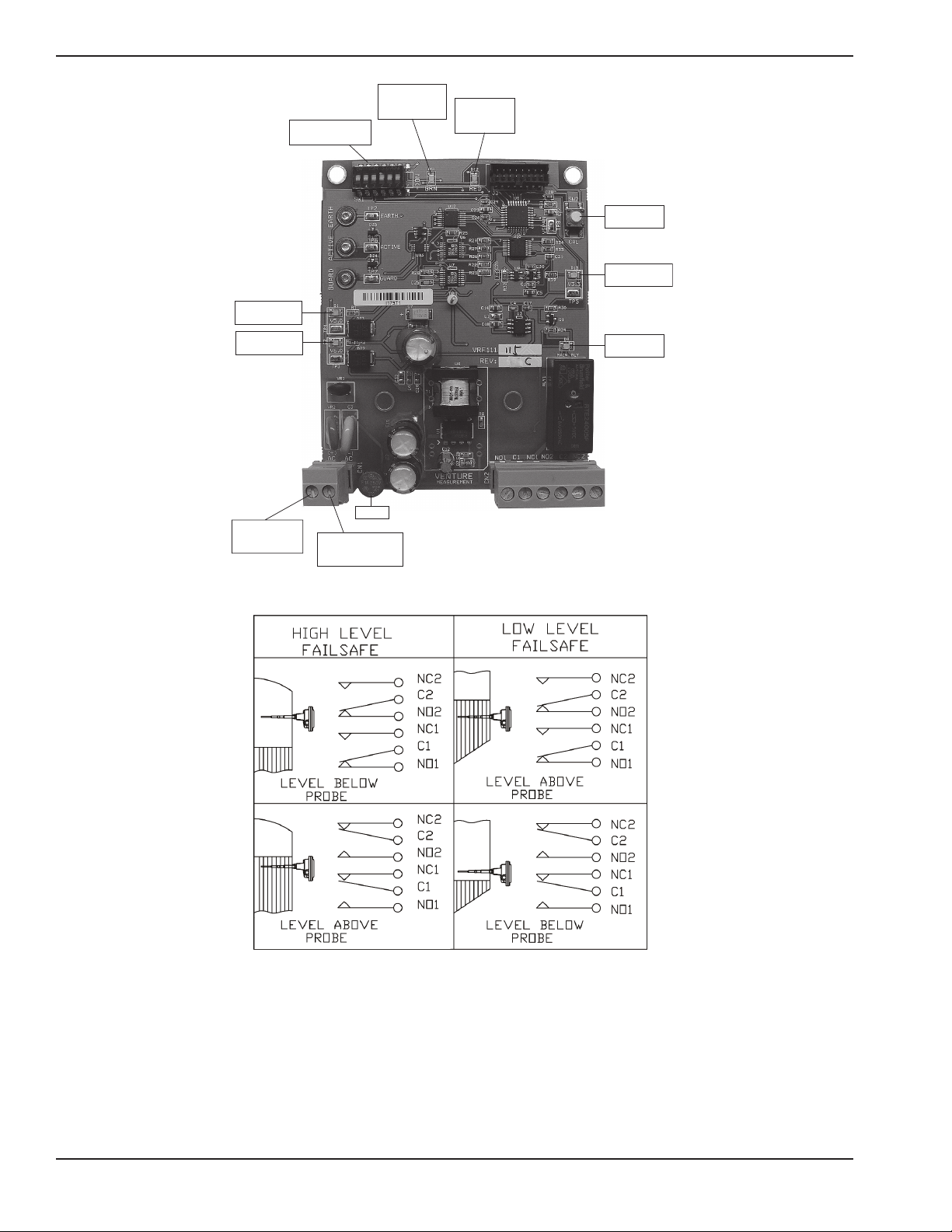
Figure 4.1 - VRF-1000 Electronics.
Figure 4.2 - High/Low Level Fail-Safe.
The output relay contacts are labeled in the un-powered alarm state. The relay is energized when the
VRF-1000 is not alarmed. This status may be opposite that of other Bindicator®brand units. If the
VRF-1000 is replacing an older Model RF-8000 or RF-9000 Series unit, connections will need to be
opposite. If a connection was made to the NC1 terminal of the RF-8000 or RF-9000 Series unit,
connect now to the NO1 terminal of the VRF-1000. C1 and C2 connections remain the same.

8
CHAPTER 5. SET-UP AND CALIBRATION
OPERATION
The VRF™ unit will begin operating when powered up. The sensitivity, fail-safe, and time delay settings
can be made without power applied. Recalibration will require that the unit be powered. Changes to
the sensitivity, fail-safe, and time delay do not require a recalibration.
SETTINGS AND ADJUSTMENTS
FAIL-SAFE SELECTION
The VRF™ is shipped from the manufacturing facility in the high level fail-safe condition. This setting is
made on DIP switch SW1, position 5. See Figure 4.1 in Chapter 4.
HIGH LEVEL FAIL-SAFE OPERATION
DIP Switch SW1 position 5 is ON.
If the electrical power fails, the relay turns OFF. This indicates material as if the tank is full.
Relay status LED is ON when no material is present, and OFF when material is present.
Alarm LED (red) is OFF when no material is present, and ON when material is present.
Relay NC output contacts are open when no material is present and closed when material is present.
NO output contacts are closed when no material is present and open when material is present.
LOW LEVEL FAIL-SAFE OPERATION
DIP Switch SW1 position 5 is OFF.
Relay status LED is OFF when no material is present, and ON when material is present.
Alarm LED (red) is OFF when no material is present, and ON when material is present.
Relay NC output contacts are closed when no material is present and open when material is present.
Relay NO output contacts are open when no material is present and closed when material is present.
SENSITIVITY SETTING
The VRF™ is shipped from the manufacturing facility in the 2pF setting. This setting is made on DIP
switch SW1 positions 1 and 2. See Figure 4.1.
TIME DELAY SETTING
The VRF™ is shipped from the manufacturing facility in the minimum time delay setting. This setting is
made on DIP switch SW1 positions 3 and 4. This setting will delay the time between when the VRF™
unit senses material and the output relay changes state. The delay is only in this direction, regardless of
fail-safe setting. There will be no delay when the material leaves the probe. See Figure 4.1.

9
ENABLE AUTOMATIC CALIBRATION FEATURE
The VRF-1000 is shipped form the manufacturing facility with the EZ-CAL™ II feature disabled (OFF).
If automatic calibration/recalibration is desired, set the SW1 DIP switch position 6 to ON. When
enabled, the unit will automatically recalibrate whenever it senses a lower capacitance than the
previously calibrated point. Sensing only air, or a lower material level than previous sensed, will initiate a
recalibration.
Note
Conductive or excessive material build-up on the Pro-Guard section of the probe will cause the probe to
recalibrate to a lower than normal point. DO NOT turn this feature on if excessive build-up is likely.
This unit can also be manually calibrated by pressing the recalibration push button. See Figure 4.1. The
probe must not have material level present when calibration is performed.

10
CHAPTER 6. START-UP AND OPERATION
The VRF-1000 will begin operating when powered up. Once properly installed in the application, it
should be calibrated when material is below the probe. If the automatic calibration feature is turned ON,
the unit will self calibrate to the current conditions, assuming that there is no material on the probe. If
there is material present, and the automatic calibration is ON, the unit will automatically recalibrate when
material level drops below the probe.
If the unit is powered on a bench prior to installation, or moved from one installation to another,
recalibration is required. Momentarily press the calibration push button. See Figure 4.1 for location.
The green calibration indication LED will turn OFF, then after 1 second will illuminate, to indicate that
calibration is complete. If the green LED is ashing, the unit is not properly calibrated. Check all ground
connections and retry.

11
CHAPTER 7. MAINTENANCE AND SPARE PARTS LIST
If it should become necessary to replace any parts on the VRF-1000 Series unit, please contact
Bindicator®at (800) 778.9242 or (864) 574.8060. Please note the model number and date code from the
nameplate located on the cover of the unit. Please have this information available at the time of calling.
A Bindicator®representative will be of assistance in identifying what replacement parts are available for
that particular model.
REPLACEMENT PROBES
PART NUMBER DESCRIPTION
LHF110016 Heavy Duty Probe (Probe 5)
LHF110044 Heavy Duty Probe, Kynar®Coated (Probe 6)
LRF110007 Standard Probe (Probe 0)
LRF110062 Food Grade Probe (Probe 2)
LRF110072 Flush Mount Probe (Probe 8)
LRF110078 Stub Probe (Probe 4)
LRF110084 Standard Probe, Kynar®Coated (Probe 1)
LRF110121 Ceramic Probe (Probe 3)
LRF110251 3/8” Thick Dome Flush Probe (Probe 7)
LRF110252 ½” Thick Dome Flush Probe (Probe 7)
LRF110253 5/8” Thick Dome Flush Probe (Probe 7)
LRF110254 ¾” Thick Dome Flush Probe (Probe 7)
LRF110905 Jumbo Probe
LRF110939 Teon®Jacketed Standard Probe (Probe T)
LRF110940 Teon®Jacketed Heavy Duty Probe (Probe U)
LRF120139 Dome Flush Probe Adapter
LRF150055 Armored Food Grade Probe (Probe A)
LRF110951 Fly Ash Probe (Probe F)
LRF110991 Mini Ceramic Probe (Probe M)
REPLACEMENT ELECTRONICS
PART NUMBER DESCRIPTION
VRF111115 Printed Circuit Board (AC)
VRF111205 Printed Circuit Board (DC)
LUC037783 1A fuse

12
CHAPTER 8. TROUBLESHOOTING
If problems are experienced with the VRF-1000 unit, check the following:
• Proper input voltage. If correct, the “Power Indication LED” should be illuminated. See Figure 4.1
for location.
• Check that a good electrical earth ground is terminated to the “Input Ground Connection” screw on
the internal housing of the unit.
• Check that the external ground wire is connected from the housing to the tank top or wall, if
mounted in a metal tank.
• Recalibrate the unit as described in Chapter 6.
• Check for excessive material build-up or physical damage to the probe.
If further assistance is needed, please contact Bindicator®Customer Care at (800) 778.9242
or (864) 574.8060.

13
APPENDIX
DRAWING NUMBER DRAWING DESCRIPTION
VRF185001 Dimensional Drawing for GP VRF-1000 and VRF-2000
VRF185002 Dimensional Drawing for VRF-1000 and VRF-2000 GP Cable Probe
VRF185003 Dimensional Drawing for Dome Flush Probe VRF-1000 and VRF-2000
VRF185004 Outline Drawing VRF Extended, G/P Type “B” Mounting
VRF185005 Outline Drawing VRF Extended, G/P Type “C” Mounting
VRF185006 Dimensional Drawing for GP VRF-1000 and VRF-2000 (Sanitary Mounting)
VRF185007 Wiring for VRF-1000
VRF185009 Dimensional Drawing for Flush Probe VRF-1000 and VRF-2000 GP/XP
VRF185010 Dimensional Drawing for VRF-1000 and VRF-2000 Teon®Coated
VRF185011 Dimensional Drawing for VRF-1000 and VRF-2000 Jumbo Probe
VRF185012 VRF-1000 and VRF-2000 Sanitary Cable Probes (Stub and Food Grade)

14

15

16

17
Table of contents
Other Bindicator Accessories manuals


