BLH NOBEL G4-HE User manual

G4 Multi Channel
Weighing Instrument
Program version 1.12.0.0
Technical Manual
PM/DT/HE types


1. Introduction
General .............................................1-1
Functions ..........................................1-2
Maintenance .....................................1-4
Safety information ............................1-4
Technical data ..................................1-5
Ordering information ......................1-12
2. Installation
Mechanical installation .....................2-1
Electrical installation .........................2-2
CPU unit............................................2-3
DC SUPPLY .....................................2-5
AC SUPPLY .....................................2-6
WF IN, WF IN2 and HS WF2 ...........2-7
AOUT1 and AOUT4 .......................2-10
DIO8 ...............................................2-11
Profibus-DP Fieldbus Adaptor.........2-12
DeviceNet Fieldbus Adaptor ..........2-14
Front panel .....................................2-16
3. Set-up
General .............................................3-1
Graphical touch display ....................3-3
Menu structure .................................3-6
Parameters .......................................3-9
Program options .............................3-46
4. Calibration
General .............................................4-1
Common parameters .......................4-2
Data sheet calibration ......................4-4
Table calibration ...............................4-5
Deadweight calibration .....................4-5
5. Operation
General .............................................5-1
Power supply ....................................5-1
Power-up sequence .........................5-1
Display alt. by normal operation .......5-2
Security locks ...................................5-4
Taring ...............................................5-5
Gross/Net operation .........................5-6
Zero setting ......................................5-6
Zero-track./Auto. zero setting ...........5-7
Motion ...............................................5-7
Weight printing .................................5-8
Batch report printing ........................5-9
Main menu .......................................5-9
Level supervision ...........................5-11
Setpoint function ............................5-12
Use of inputs and outputs ..............5-13
Filter function .................................5-13
Flow rate ........................................5-15
6. Communication
General ............................................6-1
Serial interface..................................6-1
Modbus RTU Slave ..........................6-1
Modbus TCP Slave ..........................6-2
External I/O.......................................6-3
EtherNet/IP .......................................6-4
Ftp Server.........................................6-4
Modbus protocol ..............................6-4
Fieldbus interface ...........................6-32
Fieldbus Data Definitions................6-33
Weight printing................................6-46
7. Remote Access
General ............................................7-1
Browser requirements.......................7-1
Using the Remote Access ...............7-2
Security.............................................7-2
Remote Access Login and Logout....7-3
Remote / Local Access.....................7-5
Remote Set-up..................................7-6
Remote Access Maintenance.........7-10
Instrument Restart ..........................7-18
8. Maintenance
General ............................................8-1
Diagnostics .......................................8-1
File handling ....................................8-5
Create Backup .................................8-5
Restore Backup ...............................8-6
Set Default........................................8-6
Program Upgrade .............................8-6
Instrument Restart ............................8-7
9. Troubleshooting
General.............................................9-1
Error codes ......................................9-1
Appendix
Declaration of Conformity.............App.1
Contents

Technical Manual
PRECAUTIONS
READ this manual BEFORE operating or servicing this instrument. FOLLOW these
instructions carefully. SAVE this manual for future reference.
USE IN HAZARDOUS LOCATIONS
See FM and cFM approvals.
THIS EQUIPMENT IS SUITABLE FOR USE IN CLASS I, II and III, DIVISION 2,
GROUPS A, B, C, D, E, F and G HAZARDOUS LOCATIONS or NON-HAZARDOUS
LOCATIONS.
WARNING- EXPLOSION HAZARD.
NONINCENDIVE FIELD WIRING CONNECTIONS TO CLASS I, II, III, DIV 2,
GROUPS A, B, C, D, E, F, G WHEN INSTALLED PER DWG 401706.
DO NOT REMOVE OR REPLACE CONNECTORS OR DISCONNECT EQUIPMENT
WHEN A FLAMMABLE OR COMBUSTIBLE ATMOSPHERE IS PRESENT.
TYPE 4X, INDOOR USE ONLY.
USB CONNECTION NOT ALLOWED TO BE USED IN HAZARDOUS LOCATIONS.
ATTENTION-DANGER D'EXPLOSION.
RACCORDEMENT POURATMOSPHERE NON EXPLOSIVE POUR CLASS I, II, III,
DIV 2, GROUP A, B, C, D, E, F, G INSTALLE SUIVANT PLAN 401706.
NE PAS DECONNECTER OU REMPLACER LES CONNECTEURS OU
DEBRANCHER L'EQUIPEMENT EN PRESENCE D'ATMOSPHERE INFLAMMABLE
OU EXPLOSIVE.
UTILISATION INTERIEURE UNIQUEMENT.
CONNEXION USB NON AUTORISEE EN ZONE DANGEREUSE.
INTENDED USE
The G4 Instrument family are multi-channel measuring and control devices intended for
industrial systems. Its basic function is to convert the signals from transducers to useful
information. Transducer excitation is included as well as parameter controlled signal
processing, indication of output levels, error supervision and operation of optional
external equipment.
The instrument supports several types of communication interfaces. The instruments
are modular and can be equipped with different types of I/O units. There are transducer
interface modules, digital and analog input/output modules.
!
WARNING
Only permit qualified personnel to install and service this instrument.
Exercise care when making checks, tests and adjustments that must be
made with power on. Failing to observe these precautions can result in
bodily harm.
DO NOT allow untrained personnel to operate, clean, inspect, maintain,
service, or tamper with this instrument.

G4 Multi Channel Weighing Instrument
1-1
1. Introduction
General
The G4 Instrument is a high performance multi-channel weight indicator intended for
industrial systems.
Its basic function is to convert the signals from strain gauge transducers to useful
weight information. Transducer excitation is included as well as parameter controlled
signal processing, indication of output levels, error supervision and operation of
optional external equipment. The instrument can be equipped with up to 8
synchronized weighing channels.
The instrument is modular and can be equipped with different types of I/O units to
match the demands in the specific applications. There are strain gauge transducer
interface modules, a digital input/output module, and analog output modules.
Internal solid-state outputs in the instrument can be used for output functions from level
supervision, setpoints, etc. or ‘In process’ indication, reporting the operating status of
the G4 Instrument.
The CPU unit in the instrument has several communication interfaces. It has two serial
communication ports, an Ethernet port, an USB port and a fieldbus slot.
Several G4 Instruments can be controlled from a master computer or PLC.
Serial communication interfaces are RS-485 and RS-232 for communication with a
computer/PLC (using Modbus RTU protocol) or for transmitting print out data to a
connected printer. The Ethernet interface is using Modbus TCP or (optional)
EtherNet/IP and the optional fieldbus interface uses Profibus or DeviceNet.
It is possible to access the instrument, set-up and maintenance functions, remotely
over the Ethernet connection using a Web Browser on a connected PC.
In the Weighing program there are three program options available, Flow Rate program
option, Scale Batching program option and EtherNet/IP Program option. By entering its
option code a program option is enabled. The option code can be purchased from your
supplier.
It is possible to load new software into the instrument using the USB port.
All functions in the G4 Instrument are controlled by set-up parameters. Setting of
parameter values can be performed with keys and/or graphical touch display on
the front panel.
24 V DC or 110/230 V AC powers the G4 Instrument. All input and output signals
are galvanically isolated from the power supply by operational insulation.
CPU
unit
I/O
unit
1
I/O
unit
2
I/O
unit
3
I/O
unit
4
I/O
unit
5
I/O
unit
6
Power
supply
unit
Backplane
Graphic color
display with
touch interface
Enclosure & mounting accessories
Operator panel
Key
pad
unit
Block structure of a G4 Instrument

Technical Manual
1-2
Functions
Measurement with strain gauge transducers.
Both excitation voltage and output signal are measured at the transducer to avoid
influence from voltage drop in the connection cable. Excitation to the transducer, from
the G4 Instrument is provided over separate wires.
A shielded 6-wire cable must be used to connect a distant transducer to the instrument.
A/D conversion.
The analog signals from the transducer are converted to digital form and filtered
to give an internal transducer signal with high resolution.
Calculation.
The transducer excitation and signal values are combined to form an internal
transducer signal, representing the load on the transducer. Influenced by calibration
data, this signal is converted to a digital measurement value, the weight value, which
can be presented at the local display window and at external equipment.
Error supervision.
As long as the error supervision detects no error, the signal ‘In process’ is present
but if an error is detected, ‘In process’ will be off and a specific error message will be
displayed. ‘In process’ can be set to control any digital output. Note that there are
weighing channel specific and instrument specific error detection.
Levels.
32 level comparators in the instrument can be set to switch at defined signal levels with
any selected hystereses added, meaning that the switch level can be different for
increasing and decreasing signal. Output signals from these comparators are available
on the serial communication. The level comparator outputs can also be set to control
digital outputs from the instrument.
Communication.
The G4 Instrument utilizes the serial interface, Ethernet and a fieldbus interface for
communication with control computer. The serial interface consists of a RS-232
(COM1) connection and a RS-485/RS-422 (COM2) connection. COM2 can be used
with 2- or 4-wire connection.
Weight values, level status, error status etc. can be collected and commands given
through the communication interfaces. Modbus RTU protocol is used for the serial
interfaces, Modbus TCP and EtherNet/IP for the Ethernet connection. For the optional
fieldbus interface Profibus or DeviceNet can be used.
The serial interfaces can also be used to connect a printer for printing of weight and/or
flow rate values etc. If the Scale Batching Program Option is enabled it is possible to
print batching reports.

G4 Multi Channel Weighing Instrument
1-3
Instrument modes.
In normal operation mode the G4 Instrument is presenting the measurement values on
the front panel graphical display. One or more weighing channels can be shown
simultaneously. The user can configure the display via set-up parameters.
During parameter set-up the instrument will continue normal operation. However if
hardware set-up parameters have been changed the instrument will be restarted.
The operator will always be notified before the instrument is restarted.
Parameter setting.
In the instrument all operating functions are controlled by set-up parameters with
numerical values, string values, or pre-selected values from a list of alternatives.
Parameter set-up is performed by the keys at the front panel of the instrument and/or
by using the buttons displayed on the touch display.
Presentation.
The instrument can present measured or calculated values, status of levels, parameter
settings etc. at the front panel. An extensive system of menus gives the possibility to
present various information about the instrument.
Measured or calculated values, status of levels and so on, can be transferred to
external equipment via the different communication interfaces (some are optional).
Scale Batching program option.
There is a batching function within the instrument, which is enabled with an option
code, which can be bought from the instrument supplier. The batching option gives the
possibility to perform individual batching with each scale. See the separate ‘Scale
Batching Program Option’ ‘Technical Manual Supplement’ available for the batching
option.
Flow Rate program option.
With the Flow Rate program option enabled the instrument can calculate the flow rate
based on the weight. The flow rate is calculated and set-up individually for each scale.
Flow rate can be shown on the display, sent to (optional) analog outputs and read
through any of the available communication alternatives in the instrument. An option
code is required to enable this program option. See the description of the flow rate
calculation in this manual.
Remote Access.
It is possible to access the instrument through the Ethernet connection. Using a Web
Browser on the connected PC most set-up and maintenance functions are available on
the PC. This possibility will simplify commissioning and service. It will make it possible
to access instruments from outside the local network (internet) providing the network
allow this.

Technical Manual
1-4
Maintenance
The G4 instrument needs no maintenance, performed by the end-user. Any service
or repair work must be performed by qualified personnel.
Contact your supplier.
Cleaning
Before cleaning the G4, break the power connection to the instrument.
Use a soft cloth to clean the exterior of the instrument. For cleaning
the instrument front panel, a soft, damp, cloth may be used.
Safety information
Utilization.
Before connecting power to the instrument, check that all fixation screws
at the modules are tightened so that the instruments functional grounding
by the housing is maintained.
The instrument may only be utilized for the measurement and control functions,
described in this Technical Manual. It is especially important to adhere to the load limits
of the input/output connectors. We accept no responsibility for any damage arising from
improper operation.
Any changes to the instrument, which causes any function changes, may only be
carried out by the manufacturer, or after discussion with and permission by the
manufacturer.
Meaning of symbols, used in this manual
Direct current.
Alternating current.
!
Caution, risk of danger. Documentation needs to be consulted.
G4 Multi Channel Weighing Instrument
1-5
Technical data
Enclosure
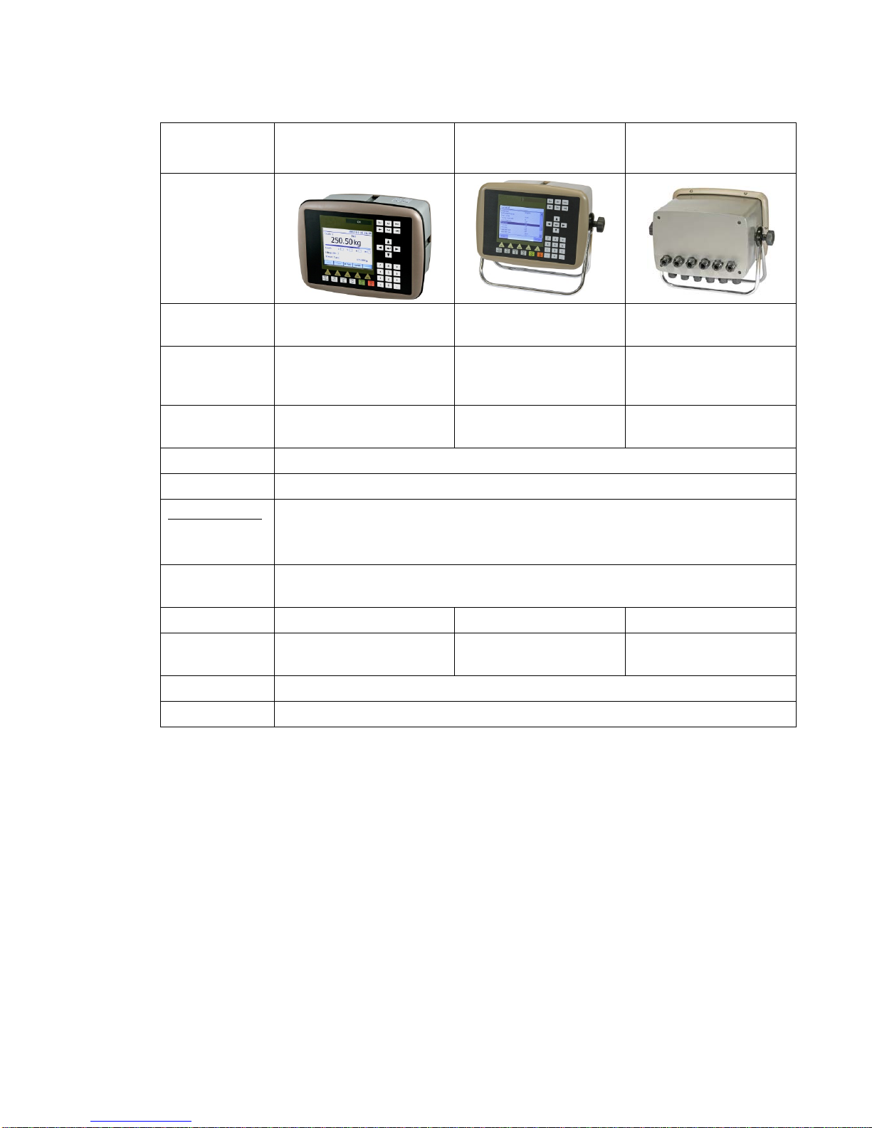
types PM - Panel mount DT – Desktop HE – Harsh
Environment
Enclosure
design Aluminum housing,
plastic panel Aluminum housing,
plastic panel Stainless steel housing,
plastic panel
Dimensions See figure
Panel thickness:
2 – 25 mm
See figure See figure
Strain relief — 6 pcs. for cable dia.
4.3 to 11.4 mm 6 pcs. for cable dia.
4.3 to 11.4 mm
Display Color TFT LCD screen with backlighting, 5.7” 320x240 pixels
Keyboard Touch screen and 34 membrane keys
Environmental
Temperature
range
Rated performance: -10 to +50 °C
Storage: -25 to +85 °C
Relative
humidity Max. 85% up to 40°C, decreasing linear to 50% at 50°C
Rated pollution Pollution degree 2 Pollution degree 3 Pollution degree 3
Protection IP65 (panel), indoor use IP65, indoor use.
Rated for wet locations IP65, indoor use.
Rated for wet locations
Altitude Up to 2000 m
EMC, RF CE (Industrial), OIML

Technical Manual
1-6
PM -Panel mount enclosure outlines and panel cutout.
DT -Desktop enclosure outlines
HE - Harsh environment enclosure outlines

G4 Multi Channel Weighing Instrument
1-7
CPU
Module type CPU module
RTC backup battery Manufacturer Type
Lithium battery Panasonic-BSG CR2032
CR2032 3V GP Batteries CR2032
Varta CR2032 (V)
COM1 (RS232) and
COM2 (RS485) For process data and control or printout data to a connected
printer. Isolated by operational insulation
Protocol Modbus RTU
Baud rate Up to 115 kbaud
Fieldbus For process data and control (optional)
Types Profibus or DeviceNet
USB Version 1
Keyboard USB keyboard for PC
USB Memory USB type for PC
For backup and restore of set-up parameters
For change to a new program version
Ethernet 10/100BASE-T. For process data, control, file transfer and
remote access.
Protocols Modbus TCP, EtherNet/IP, ftp, http.
RJ45 Indications Green LED: Transmitting. Yellow LED: Receiving.
DC SUPPLY
Module type Power supply module
Input 24 V ±15% including fluctuations, 40W
Impulse withstand (overvoltage)
category I of IEC 60364-4-443
Output 24 V output 0.1 A
The same voltage as input voltage

Technical Manual
1-8
AC SUPPLY
Module type Power supply module
Input voltage 110-240 V~ +10% -15% including fluctuations, 50/60 Hz,
40W
Impulse withstand (overvoltage)
category II of IEC 60364-4-443
Output voltage 24 V output 0.1 A
WF IN / WF IN2
Module type Weight/Force input module
Max. # of transducers 8 (350 ohm) per channel
Maximum 48 transducers per instrument
Excitation voltage: 5 VDC
A/D conversion: 3.9 kHz, 16 000000 units (24 bits)
Input range +/- 7 mV/V
Update rate: 2.3 −300 readings per second
No. of channels: WF IN has 1 Weight/Force channel
WF IN2 has 2 Weight/Force channels
Sensitivity: 0.1 µV
Zero drift: <10 nV/V/K
Span drift: <2 ppm/K
Digital I/O 4 inputs, 24 V ±15%, 5 mA from external power supply,
isolated by operational insulation
and with common return
2 outputs, 24 V ±15%, max 100 mA from external
power supply, isolated by operational insulation
and with common return

G4 Multi Channel Weighing Instrument
1-9
HS WF2
Module type High Speed Weight/Force input module
Max. # of transducers 4 (350 ohm) per channel
Excitation voltage: 10 VDC
A/D conversion: 20 kHz, 16 000000 units (24 bits)
Input range +/- 4.5 mV/V
Update rate: 12.5 −800 readings per second
No. of channels: HS WF2 has 2 Weight/Force channels,
separately isolated by operational insulation
Sensitivity: 0.1 µV
Zero drift: <10 nV/V/K
Span drift: <2 ppm/K
Digital I/O 4 inputs, 24 V ±15%, 5 mA from external power supply,
isolated by operational insulation
and with common return
2 outputs, 24 V ±15%, max 100 mA from external power
supply, isolated by operational insulation
and with common return
DIO8
Module type Digital input/output module
Separate I/O module 2 units can be used
Digital I/O 8 inputs, 24 V ±15%, 5 mA from external power supply,
isolated by operational insulation
and with common return
8 outputs, 24 V ±15%, max 100 mA from external power
supply, isolated by operational insulation
and with common return

Technical Manual
1-10
AOUT1 / AOUT4
Module type Analog output module
Number of channels 1 or 4 channels,
separately isolated by operational insulation
Resolution 65000 units, 16 bits
Voltage output 0 – 10 V, -10 – 10 V, > 1 kohm load
Current output 4 – 20 mA, 0 – 20 mA, -12 – 20 mA, -20 – 20 mA,
< 500 ohm load
Update rate Scale update rate, adjustable smoothing filter
Profibus-DP
Module type Profibus-DP fieldbus adaptor
Connector Profibus 9-pin, female D-sub (DB9F)
Baudrate Auto setting 9.6 kbps – 12 Mbps
Address 1 – 125, set by parameter
Fieldbus data 16 bytes from fieldbus to instrument.
32 – 244 bytes from instrument to fieldbus (may be limited
by the master).
See chapter ‘Communication’ section
‘Fieldbus communication interface’ for details on fieldbus
data mapping.
Mounting The fieldbus adaptor is mounted through the front of
the CPU module with LED’s and connector accessible
through the CPU front panel.
Remove the plastic cover from the fieldbus slot in the CPU
module front panel. Insert the adaptor very carefully and
make absolutely sure that the adaptor slides correctly into
the guides in the connector on the CPU PCB. Tighten
the two fastening screws at the adaptor front and check
that the two securing hooks locks into the CPU PCB.
Settings All fieldbus settings are done with setup parameters in
the instrument. No settings are done on the module itself.

G4 Multi Channel Weighing Instrument
1-11
DeviceNet
Module type DeviceNet fieldbus adaptor
Connector 5 pin male connector.
Baudrate 125, 250, 500 kbps or Auto. Set by parameter.
Address 0 – 63, set by parameter
Fieldbus data 16 bytes from fieldbus to instrument.
32 – 244 bytes from instrument to fieldbus (may be limited
by the master).
See chapter ‘Communication’ section
‘Fieldbus communication interface’ for details on fieldbus
data mapping.
Mounting The fieldbus adaptor is mounted through the front of
the CPU module with LED’s and connector accessible
through the CPU front panel.
Remove the plastic cover from the fieldbus slot in the CPU
module front panel. Insert the adaptor very carefully and
make absolutely sure that the adaptor slides correctly into
the guides in the connector on the CPU PCB. Tighten
the two fastening screws at the adaptor front and check
that the two securing hooks locks into the CPU PCB.
Settings All fieldbus settings are done with setup parameters in
the instrument. No settings are done on the module itself.
Bus Supply Voltage According to the DeviceNet (Node) Specification:
nominal 24 VDC, range 11 – 25 VDC.

Technical Manual
1-12
Ordering information
For Panel mount (PM), Desktop (DT) and Harsh environment
(HE) instruments
G4-PM-FB-S1-S2-S3-S4-S5-S6-P-SW
Instrument type
PM Enclosure type PM
DT
HE
Panel mount
Desktop
Harsh environment
FB Fieldbus interface 0
P
D
None
Profibus
DeviceNet
Si Slot 1 to 6 type 0
2
3
4
6
7
8
Blank
HS WF2 High speed weight/force input module, 2 ch
WF IN Weight/force input module, 1 channel
WF IN2 Weight/force input module, 2 channels
AOUT1 Analog Output module, 1 channel
AOUT4 Analog Output module, 4 channels
DIO8 Digital Input and Output module
P Power supply D
A DC power supply
AC power supply
SW Software (note 1)
W
F
S
(No code specified) Standard Weighing Program
Standard Weighing Program
Standard Force Program
Special Program (note 2)
Example: G4-PM-0-4-8-0-0-0-0-D-W
•G4 instrument (G4)
•Panel mount (PM)
•No fieldbus (0)
•Slot 1 = WF IN2 (4)
•Slot 2 = DIO8 (8)
•Slot 3 = Blank (0)
•Slot 4 = Blank (0)
•Slot 5 = Blank (0)
•Slot 6 = Blank (0)
•Power =DC supply (D)
•Software = Weighing program (W)
Note 1: The Software (SW) code specifies the program function that should be installed
in the instrument. If no code is specified the standard Weighing program will be
supplied.
Note 2: If a special program option is desired, the designation of the special program
must be specified when ordering.

G4 Multi Channel Weighing Instrument
1-13
Separate modules
Spec.no
Module type Module name
110 544
CPU CPU unit
110 546
HS WF2 High speed dual Weight/Force input module
110 547
WF IN Single Weight/Force input module
110 548
WF IN2 Dual Weight/Force input module
110 549
AOUT1 Single channel analog output module
110 550
AOUT4 Four channel analog output module
110 551
DIO8 Digital input/output module
110 552
BLANK Blank panel
110 553
DC SUPPLY DC supply unit
110 630
AC SUPPLY AC supply unit
110 559
PROFIBUS-DP Profibus DP fieldbus adaptor
110 560
DEVICENET DeviceNet fieldbus adaptor
Module selection rules
Every system needs 1 Power supply module and 1 CPU module (can be equipped with
one fieldbus adaptor).
Limitations on number of I/O modules that can be used in one instrument:
•Maximum 6 modules.
•Maximum 4 WF IN / WF IN2 or 2 HS WF2 modules.
•HS WF2 and WF IN(2) cannot be mixed in the same system.
•Maximum 1 AOUT1 or 1 AOUT4 module.
•Maximum 2 DIO8 modules.

Technical Manual
1-14

G4 Multi Channel Weighing Instrument
2-1
2. Installation
Mechanical installation
See chapter ‘Introduction – Technical data’ for references to PM, DT and HE
mechanical measures: outer extents, body extents and panel cutout (PM).
PM type instrument:
Make sure the panel thickness meets the specification and that there is room enough
behind the panel for the instrument and the connected cables (minimum 200 mm).
Cut a panel opening according to the specification on page 1-5.
Insert the instrument through the opening. Hold it in place while attaching brackets
and wing-headed bolts to the four nuts, sliding in grooves of the housing.
Tighten the bolts and make sure the integrated gasket of the instrument is
compressed against the mounting panel, giving a sealed attachment.
DT and HE type instrument:
Arrange enough space for cables and strain reliefs behind or below the instrument.
DT instrument housings have 6 plugged openings facing downwards, intended for
the cable strain reliefs. As an alternative, knock-out openings in the back panel can be
knocked open for strain reliefs facing backwards.
HE instrument housings have 12 plugged openings for the cable strain reliefs, facing
downwards and backwards.
Enclosed with each instrument is a set of 6 strain reliefs. For each cable one strain
relief should be mounted with a sealing washer on the exterior and a locknut inside
the housing.
Mounting legs are fitted to the instrument housings by knob-headed bolts and threaded
holes or nuts. Use the enclosed fixing brackets to attach the legs to the table or a wall.
295
278
150 108
Dia. 4.4
Dia. 4.4
DT and HE instruments.
Fixing bracket, recommended distances to surrounding surfaces.

Technical Manual
2-2
Electrical installation
The field wiring of the instrument shall be suitable to the environment
(e.g. chemically) in the end-user application.
Mains cables shall be separated and routed away from SELV or
SELV-E field wiring.
For DT and HE instruments UL Listed and KAM cord type flexible cables shall be used.
The cable diameters must be selected in accordance with the strain relief specification.
See Technical Data.
Field wiring installation shall comply with any national regulations, hereunder National
Electrical Code (NEC) for US and/or Canadian Electrical Code for Canada.
•A switch or circuit-breaker shall be included in the building installation.
•The switch shall be in close proximity to the equipment and
within easy reach of the operator
•The switch shall be marked as the disconnecting device for the equipment.
•The equipment switch or circuit-breaker employed as disconnecting device shall
comply with relevant requirements of IEC 60947-1 and IEC 60947-3.
The power supply for the instruments can be
an external DC source and an internal DC SUPPLY unit
or external AC mains and an internal AC SUPPLY unit.
For electrical installation with an internal DC SUPPLY unit, see page 2-5.
For electrical installation with an internal AC SUPPLY unit, see page 2-6.
WARNING
Make sure that that the power to the instrument is turned off before:
-any modules are removed from or inserted in the instrument.
-any connections are connected to or disconnected from the instrument.
All modules should be regarded as ESD sensitive. Make sure that an ESD safe
environment is maintained when inserting modules, removing modules and when
handling modules separately from the instrument. Modules must be kept in
metallised ESD bag when not mounted in the instrument.
!
This manual suits for next models
2
Table of contents
Other BLH NOBEL Accessories manuals


