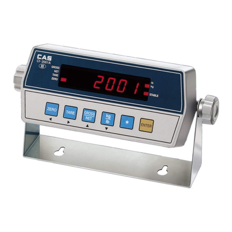
CAS CI-6000A Series User manual

2

3
Contents
1. Introduction......................................................................... 4
2. Features................................................................................ 6
3. Technical Specification...................................................... 7
4. Measure of Appearance.................................................... 9
5. Front Panel ........................................................................ 10
6. Rear Panel ......................................................................... 14
7. How to Install.................................................................... 15
8. Calibration Mode............................................................. 16
9. Set Mode ............................................................................ 24
10. Test Mode......................................................................... 43
11. Weighing Mode............................................................... 47
12. Serial Interface(COM1, COM2) ................................ 63
13. Options ............................................................................. 67

4
1. Introduction
Thank you for purchasing the CAS CI-6000A weighing indicator.
We have designed this equipment with many advanced features, high quality construction, and user-
friendly menu driven programming.
CAS indicator is shaped firmly and delicately designed to coincide with the special requirements of
several industrial fields and includes many functions and various external interfaces. Also, it contains
help display functions to be used easily.
Before using CI-6000A, It is recommended to read this manual carefully and to apply
the function application fully.
Precautions
Observe the following safety precautions :
Warning
When any damage or defect
occurs, contact your CAS
authorized dealer immediately
for proper repair.
Insert plug firmly to wall outlet to
prevent electric shock.
Scale must be grounded to
minimize electricity static. This
will minimize defect or electric
shock.
Do not pull the plug by its cord
when unplugging. Damaged
cord could cause electric shock
or fire.
To prevent from fire occurring,
Do not place or use the scale
near flammable or corrosive
gas.
To reduce electric shock or
incorrect reading, Do not spill
water on the scale or place it in
humid condition.

5
Avoid placing the scale near
heather or in direct sunlight.
Attention
For consistent and accurate
reading, maintain periodical
check by your CAS authorized
dealer.
Avoid sudden shock to the scale.
Internal mechanism could by
damaged.
Attach the rubber pad to the
bottom of the indicator.
Elimination is possible.
Place the scale on firm and
temperature consistent
environment.
Keep the scale away from the electromagnetic generation devices.
This may interfere with accurate reading.
Our Dealers :
CAS feels that each of its valued customers should get the best service
available.
Whether it’s the initial installation of our product, maintenance/repair work, or simply answering
questions about our products, CAS Corporation and all of its Authorized Dealers are highly trained to
assist you with any need regarding CAS products.

6
2. Features
1) Features
■High speed, High accuracy
■The adoption of high speed micro processor
■A/D conversion speed : Maximum 200 times/sec
■Appropriate for weighing and measurement system
■Easy operation and various options
■Simple and prompt Full Digital Calibration
(SPAC
TM : Single pass automatic span calibration)
■RFI/EMI screened
■WATCHDOG circuitry (System restoration)
■WEIGHT BACK-UP
(Weight memory at sudden power failure)
2) Main Functions
■Save date, time and calculated data at sudden power failure
■Various specification of weight conversion speed
(Digital filter function)
■Various printer connection (RS-232C Serial printer)
■Tare weight setting with keys
■Storage of measured times
■Read / Write Set-point values(7) through the PC
- each to set-point code(0~49)
■Read / Write Set Mode values(23) through the PC
■External 6 relays for input / 8 relays for output
■Users can set the max. weight and a division freely
■Control various external equipment by inner external input/output
■Print date and time by built-in clock
■Self hardware test.

7
3. Technical Specification
■Analog Part & A/D Conversion
Load Cell Excitation Voltage 8 x 350Ωload cells
Zero Adjustment Range 0.05mV 20mV∼
Input Sensitivity 0.6μV/D
System Linearity Within 0.01%of FS.
A/D Internal Resolution 1 / 1,000,000
A/D External Resolution 5,000 dd, 10,000 dd (Max)
A/D Conversion Speed Maximum 200 times/sec
■Digital Part
Span Calibration Full Digital Calibration : SPAC™
(Single pass automatic span calibration)
Input Noise Under ±0.3μVpp
Input Impedance Over 10M Ω
Display VFD (7 digit)
Size of letter 13mm (Height)
Minimum division x1, x2, x5, x10, x20, x50
Display below zero “ - ”
"ZERO" ▼Current weight of “0” kg
"STABLE" ▼Weight is stable
"GROSS" ▼Gross weight is displayed
"NET" ▼Net weight is displayed
"TARE" ▼Tare function is activated
"HOLD" ▼Hold function is activated
" * " ▼" * " key is pressed (print key)
Automatic print is set.

8
■General Specification
AC 100 ~ 240V (50/60 Hz) Input
DC +3.3V Digital Logic
DC +24V External I/O
DC +5V Analog, Load Cell
Power
AC 3.6V VFD
Product Size 192(W) x 189(D) x 96 (H)
Temperature Range -30 ~℃+60℃
Product Weight Approx. 2.4 kg

9
4. Measure of Appearance

10
5. Front Panel
1) VFD Display
■Display Lamp(▼)
ZERO lamp Current weight is 0 kg
ST lamp Weight is stable
GROSS lamp Current weight is gross weight
NET lamp Current weight is net weight
TARE lamp Tare weight is saved
HOLD lamp Lamp is on when HOLD function is activated
Lamp is on only when “*” key is pressed. And F23 is
set to “1” in the set mode
* lamp Automatic print should be set to “1” in set mode
(F41 = 1 or 2, F42 = 1)

11
2) Keyboard
You can use these keys as numeric keys
Change the set value
key increases set value and key decreases set
value
Change the position of cursor
key moves one digit to right, key moves one digit
to left
Use 1 Enter tare weight
Use 2 Enter set-point value
Use 3 Enter the set value in TEST, CAL, SET mode
■[ ZERO ]Key
Used to remove small variations in the indicator’s zero
■[ TARE ] Key
Used to weigh an item by using the container
Current weight is memorized as tare weight
If you press TARE key in unload condition, tare setting is released
■[ KEY TARE ] Key
When you already know the tare weight, press KEYTARE Key
and enter tare weight by pressing arrow keys and save it by pressing ENTER key
■[ G/N KEY ] Key
Toggles the display between gross and net weight
G. weight lamp on - gross weight / N. weight lamp on - net weight
If tare weight is saved, tare plus item's weight is gross weight and only item's weight is net weight
You can prohibit using of keyboard by pressing G/N key for 5 sec.
To use keyboard again, press G/N key for 5 sec

12
■[ * KEY ]Key
Used to set set-point value for batching operation.
(Press * key for 3 seconds more and take off)
You can select this function in set mode F23
0 : Do not use.
1 : PRINT Key.
2 : HOLD Key
■[ ENTER KEY ] Key
Set set-point code for batching operation.(00~49)
(Press the ENTER key for 3 seconds more and take off)
You can select this function in set mode F24.
0 : Do not use.
1 : TOTAL PRINT key.
2 : START key for batching operation.
3 : STOP key for batching operation.
In calibration, test, set mode : Save current condition and exit

13
3) Slide Switch
Calibration mode
Switch DIP 1 on Go to calibration mode
SW1 DIP 1
Switch DIP 1 off After calibration, it returns to weighing mode
Set mode
Switch DIP 2 on Go to set mode.
SW1 DIP 2
Switch DIP 2 off After set mode, it returns weighing mode.
Test mode
Switch DIP 3 on Go to test mode.
SW1 DIP 3
Switch DIP 3 off After test, it returns to weighing mode
It is used in calibration mode when zero value is high
SW2 DIP 1
If you set DIP 1 to on, zero value is decreased.
It is used in calibration mode when zero value is low
SW2 DIP 2
If you set DIP 2 to on, zero value is increased

1
4
6. Rear Panel
CONTROL I/O
LOADCELL
OPTION
T250mA
L250V
COM2
AC
COM1
COM1
RS-232 cable( 2 : TxD, 3 : RxD, 5,7 : Gnd )
- F33 = 1 ~ 4 function is enable (both of Set-point and Set-
mode) to read and write
- Computer, sub-display and printer
COM2
RS-232 cable( 2 : TxD, 5,7 : Gnd)
- F36 = 1 ~ 2 function is enable to read only
RS-485/422 cable( 6 : Rx+, 7 : Rx-, 8 : Tx+, 9 : Tx- )
- F36 = 1 ~ 4 function is enable(Set-point) to read and write
LOAD CELL Port for connecting. 4-wires, 6-wires load cell
External
input ZERO, TARE,START,STOP,*,ENTER key
CONTROL I/O External
output External output for batching operation
OPTION When option is used, please connect
AC 100 ~ 240VAC are available
FUSE T250mA L250V

15
7. How To Install
1) Load cell connection
Connect load cell connector to load cell port which is in the backside CI-6000A
* Connecting method
PIN
1 (EXC+)
2 (SEN+)
3 (EXC-)
4 (SEN-)
5 (SIG+)
6 (SIG-)
7 (SHIELD)
Note 1. In case of 4 wires L/C connect EX+ with SEN+, and connect EX- with SEN-.
Note 2. Wire color can be different depending on the load cell’s manufacturer or its model
2) Power
Adjusted to 220V 50/60Hz at factory.
(If you want to use 110V, adjust 110V/220V jump wire which is located
in the inner part of CI-6000A)

16
8. Calibration Mode
1) How to enter the Calibration Mode.
Open the front cover of indicator and set SW1 DIP1 to on.
At this time, message is shown on the display and is started.
After done and off the SW1 DIP1, back to the weighing mode.
2) Availabe keys.
KEY : Change the set value.
key increases set value and key decreases set value.
KEY : Change the position of cursor.
key moves one digit to right, key moves one digit to left.
ENTER KEY : The program is moved into next menu.
3) Calibration menu(CAL1~CAL7)
CAL 1 : Maximum capacity
CAL 2 : Minimum division
CAL 3 : Setting Weight
CAL 4 : Zero calibration
CAL 5 : Span calibration
CAL 6 : Check Micro Span calibration
CAL 7 : Weight Factor

1
7
CAL 1
FUNCTION : Maximum Capacity Set (Range : 1 ~ 99,999)
KEY DISPLAY DESCRIPTION
C = 05000 5000 kg
C = 0500.0 500.0 kg(First decimal point)
:
Increase or decrease
of number
:
Shift of cursor position
ENTER :
Save and go to next
menu
C = 050.00 50.00 kg (Second decimal point)
Note 1. The maximum capacity means the maximum weight of the indicator.
Note 2. The max. weight is changed depending on the decimal point.
CAL 2
FUNCTION : Minimum Division Set (Range : 0.001 ~ 50)
KEY DISPLAY DESCRIPTION
d = 1 1 kg
d = 0.2 0.2 kg (First decimal point)
d = 0.05 0.05 kg (Second decimal point)
:
Increase or decrease
of number
ENTER :
Save and go to next
menu
d = 0.001 0.001 kg (Third decimal point)
Note 1. The minimum division means the value of one division.
Note 2. The value of one division is changed depending on the decimal point.
Note 3. External resolution is obtained by dividing the maximum capacity into the min. division.
Set the resolution to be within 1/10,000.
If it is over 1/10,000, error message "Err 20" is displayed

1
8
CAL 3
FUNCTION : Setting Weight In Span CALIBRATION
KEY DISPLAY DESCRIPTION
L=05000 5000 kg
:
Increase or decrease
of number
:
Shift of cursor position
ENTER :
Save and go to next
menu
L=0500.0 500.0 kg (First decimal point)
Note 1. The setting weight should be within the 10 % to 100 % of maximum weight
100% of maximum weight is set as a default but you can change it for your needs
If the setting weight is under 10%, error message "Err 22" is displayed
If the setting weight is over 100%, error message "Err 23" is displayed
CAL 4
FUNCTION : Zero Calibration
KEY DISPLAY DESCRIPTION
Remove an item from the platter
and press ENTER key.
Zero calibration.
ENTER :
Zero calibration and
next
ZERO :
Only zero calibration
TARE :
Only span calibration
CAL 4
Analog value of
load weight state
- - -
Zero calibration is finished.
You will go to span
calibration(CAL 5)automatically.
Note 1. If Zero calibration is done without any error, You will go to span calibration (CAL 5)
automatically.
Note 2. If the zero value is too low, error message "Err 27" is displayed.
Note 3. If the zero value is too high, error message "Err 26" is displayed.
Note 4. If you want to do only zero calibration, unload the platter and press the "ZERO" key.
In a few moment, you will see "ZEro" and "CAL End" messages are displayed.
Set SW1 DIP1 to OFF and then return to the weighing mode.

19
CAL 5
FUNCTION : Span Calibration
KEY DISPLAY DESCRIPTION
Load the weight which was set in
CAL 3 and press ENTER key.
Span calibration.
ENTER :
Span calibration
CAL 5
Analog value of
load weight state
- - - Span calibration is finished.
You will go to micro span
calibration(CAL 6) automatically.
Note 1. If span calibration is done without any error,
you will go to micro span calibration (CAL 6) automatically.
Note 2. If the span value is low,
error message "Err 24" is displayed. Calibrate with lower resolution.
Note 3. If the span value is high, error message "Err 25" is displayed.
CAL 6
FUNCTION : Check Micro Span Calibration
KEY DISPLAY DESCRIPTION
500.0 Setting weight is shown on the
display.
ENTER : Save and
go to next menu
▽▽▽▼▽▽▽ Check the setting weight and set
SW1 DIP1 to off.
Note 1. Confirm if the displayed weight is equal to the setting weight that you have
set in CAL 3 and remove the weight from the platter.
If "0" is displayed, set SW1 DIP1 to OFF then you will go to normal mode.
Note 2. The bias is "0" when the central lamp lights up as above display.
Each lamp means the bias of -0.3, -0.2, -0.1, 0, 0.1, 0.2, 0.3 from the left lamp

20
CAL 7
FUNCTION : Weight Constant Calibration
KEY DISPLAY DESCRIPTION
:
Enter password.
ENTER : Exit
FACtor Enter password.
Note 1. Users do not have to use this menu, since it is used for calibration test without a
weight.

21
4) Error Message (In CAL Mode)
Error 20
▣Reason
The resolution exceeds 1/10,000
Solution☞
Lower the resolution.
The resolution = allowed weight/one division.
Modify the allowed weight in CAL1 or modify the division in CAL2 so that
the resolution is below 1/10,000
Error 22
▣Reason
The weight for span calibration is lower than 10% of the maximum
capacity of the indicator
Solution☞
Set the weight for span calibration in CAL 3 to be greater than 10% of the
maximum capacity
Error 23
▣Reason
The weight for span calibration exceeds 100% of the maximum capacity
of the indicator
Solution☞
Set the weight for span calibration to be within the maximum capacity of
the indicator in CAL 1
Error 24
▣Reason
Span value is too low
Solution☞
Load cell is damaged or setting of current resolution is not possible.
Calibrate with less resolution
Table of contents
Other CAS Accessories manuals

CAS
CAS CI-502A User manual

CAS
CAS CI-2001A User manual

CAS
CAS EXP-2000A User manual

CAS
CAS HDI User manual

CAS
CAS CI-600D Series User manual

CAS
CAS DH User manual

CAS
CAS CI-100A Installation and operating instructions

CAS
CAS CT100 Series User manual

CAS
CAS CI-400 Series User manual

CAS
CAS BI-100R User manual
Popular Accessories manuals by other brands

Philips
Philips EasySense manual

Technische Alternative
Technische Alternative RAS PLUS DL Operation, Programming, Installation Instructions

Elko
Elko iNels RFDSC-71N quick start guide

Distech Controls
Distech Controls GS-AQR Hardware installation guide

Rice Lake
Rice Lake IQ plus 800 Installation & operation manual

Beta
Beta AS-35 Operation manual