Bio-Tek Biolux HOS Series User manual

Owner's Manual
For Your New Biolux HOS Series
The Best Choice for Your Family’s Health and Hygiene
Drinking
Disinfection
Healthy Drinking Water | Natural Sanitizer

Table of Contents
HOS - Hydrogen & Ozone Water System
Introduction
To Our Valued Customers
Intended Use
Important Safety Warnings and Precautions
Product Features
Product Specications
2
2
3
5
5
Installation
Package Contents
Unit Overview
LCD Display & Control Panel
How to Install the Unit
6
7
8
11
Operation & Use
Unit Start-Up
Directions for Product Use
Other Functions
Recommendations for Using this Unit
19
20
22
27
Service & Maintenance
Consumable Parts
Troubleshooting Guide
EOS7130-HU_EN_V208
29
30

Introduction
2
To Our Valued Customers
We are not responsible for any accidents and/or malfunctions due to improper use of this product.
•
Please refer to this manual often when you have questions during the use or when troubleshooting this unit.
•
Thank you for purchasing Biolux HOS - Hydrogen & Ozone Water System. You have just purchased the nest,
most benecial and advanced health appliance in the world! Your new HOS is designed to provide you with many
years of the cleanest, healthiest and most “functional” benets available. There are many specic uses of this
amazing product, so read this manual carefully to learn how to get both optimum performance out of your HOS
Unit and to protect your investment.
This product is intended for domestic use only. Please read all safety warnings and this User’s Manual carefully
before using this product to ensure proper product usage. (Keep the manual handy for easy reference.)
Intended Use
This device not only provides saturated hydrogen water for drinking, but also ozonated water for sanitation. This is
a real one product for unlimited benets for your home!
Just exactly what are those? Your HOS employs computer accurate low-voltage electric current and selectable
proton exchange energy to perform water electrolysis through patented Indirect Electrolytic Ozone Generation
(iEOG) cell. Inside this advanced cell, driving force from the electric current and proton exchange energy split
water into pure hydrogen gas (H2) and high portion ozone (O3) contained oxygen gases (O3+O2) without using any
chemicals. Then, the hydrogen water and ozonated water are to be created by dissolving these gaseous streams in
water individually once usage is requested.
Therefore, you can choose between Hydrogen Water for Drinking (the upper button) and Ozone
Water for Disinfection Use (the lower button):
This is the natural bactericidal agent and disinfectant, effective against infestation of harmful
bacteria and virus as well as dangerous chemical and pesticide residues. It is highly effective,
efcient and free of residues.
Ozone Water
High-reducing power hydrogen water helps neutralize harmful free radicals, which further helps with
health improvement, anti-oxidation and anti-aging.
Hydrogen Water

Introduction
Important Safety Warnings and Precautions
Please read these pages carefully. They contain very important information to protect you and the valuable
warranty on your unit. Please make sure you are familiar with all the safety warning and precautions associated
with this unit.
WARNING
Could cause personal injury or have an adverse effect on health.
Never drink ozonated water. (Ozone water is for disinfection only, not for drinking.)1.
2. Only use potable drinking water in your HOS. It is recommended that you use potable municipal water as
source water (raw water).
3. Poor water quality may have negative effects on your health and your HOS! Most potable municipal water
sources will be ne in your unit. If on hard water please ask about pre-treatment options.
4. Well water and water from smaller system should be checked, and may require pre-ltering. Your HOS is not
under warranty for any damage or required cleaning by hard or poor quality water deposits.
5. Do not move the unit by the front cover. Move the unit by putting both hands underneath it. This will prevent
the unit from falling during movement.
DANGER
1.
2.
3.
4.
5.
6.
7.
To reduce the risk of electric shock, do not remove cover; no user-serviceable parts inside. Refer servicing to
qualied service personnel. Remove the cover will void the warranty.
Do not try to x the unit yourself. Call the dealer to have it xed by a qualied technician.
Do not use if the power cord is damaged or in a loose power outlet.
Never run hot water through this unit. Connecting it to a hot water (>35°C) source could damage the iEOG cell
or other parts of the HOS.
Power and water MUST be connected at all times! Do not plug and unplug power cord repeatedly. The
product’s limited warranty does not cover any damage to the iEOG cell resulting from power disconnection for
many times repeatedly. Reconnecting power for 72 times (or more) a year will void the limited warranty to the
entire product.
Protect your unit from freezing temperatures or from direct sunlight.
Keep the unit and power cord away from hot surfaces or appliances – failure to do so may result in electric
shock or re!
Could cause damage to HOS and possibly void the warranty.
Risk of Fire and Electric Shock
CAUTION
3

Introduction
These safety precautions and warnings are provided at YOUR benefit to your health and home,
for the safe and proper use of this unit and can prevent danger, bodily harm and/or possible damage
due to misuse.
Please make sure you are familiar with all the safety precautions and warnings associated with
this unit.
Biolux is not responsible for any damage or injury caused by not adhering to these precautions and
warnings.
When moving the unit, please be sure not to drag by the power cord as this could cause electric shock.
Do not place ANY objects on top of this unit regardless of how small.
Do not pull the power cord. Never touch power cord or power outlet with wet hands.
Do not use power surge protectors with this unit. Use unit with its own dedicated power source.
Do not forcibly bend, squeeze, damage or crush the power cord under heavy objects.
Do not use the unit in a dusty place. This may cause the unit to malfunction.
Do not spray water on the main unit. Do not clean with a damp cloth or any chemicals, which may leak into
the unit.
Do not place this unit on an uneven surface. Do not drop or use excessive force on this unit.
Place this product near a sink and always allow water to drain into the sink and drain.
Please be sure to keep the power cord dust free.
In case water leaks out of the unit (other than hoses) or unit is standing in a puddle of water, shut off the
water supply, unplug the power cord and refer servicing to qualied service personnel.
In the event that water gets into power supply, unplug the power cord and completely dry power outlet.
In case of strange noises, burning odor or smoke, unplug the power cord immediately and refer
servicing to qualied service personnel.
Replace pre-filter at least every 12 month or follow the recommendation from manufacturer in order to
optimize the purication performance of this unit even if the replacement indicator light isn’t turned on.
Do not poke or scratch the touch pad or LCD display with sharp objects.
Keep original packaging for storage or unit transportation.
If the power cord develops a break or short, stop using the unit and call customer service to have it replaced.
Do not reconnect or splice a defective power cord as it could result in electric shock or become a re hazard.
8.
9.
10.
11.
12.
13.
14.
15.
16.
17.
18.
19.
20.
21.
22.
23.
24.
25.
4

Introduction
Product Features
Touch button and color LCD screen for simple operation.
•
For health improvement, anti-aging and home sanitation.
•
99.999% pure Hydrogen and NOx-Free Ozone in outputs.
•
Zero latency operation, high concentrations right on starting-up.
•
Built-in gas-liquid separation and off-gas destruction at all time.
•
ORP (oxidation-reduction potential) and mv (millivolts) displays.
•
ppm (concentration of dissolved ozone) display.
•
Automatic self-cleaning and internal disinfection.
•
Food-grade and antioxidant/ozone-compatible piping and plumbing materials.
•
Certications granted by major global authorities in certication of disinfection.
•
Sufcient ow design for family use.
•
Modern design for enhanced decor.
•
Remark: The output concentrations may vary depending on intervals of usage and inuences from input pressure
and temperature.
Product Specications
5
Model: EOS7130-HG
Activation method
Output Features Hydrogen Water
Upper button 0.2s (5min output)
90L/hr (1.5L/min)
1.1~1.2 ppm
(Dissolved Hydrogen)
-518 ~ -558 mV
Neutral (No change to water pH)
2~7kg/cm2(3kg/cm2is optimal.)
AC 100 ~ 240V / 50 ~ 60Hz
60W (In standby≤30W)
300(W) x 165(D) x 400(H) [mm]
7.5kg (Around 9.5 kg at a full level)
Tap water that meets quality criteria for drinking water
(hardness of <200 ppm CaCO3, residual chlorine of <0.1 ppm, conductivity of <500 μs/cm, pH6.8~8.0)
4.3 ppm
(Dissolved Ozone)
-
4.3 - 1.0 ppm
(Dissolved Ozone)
180L/hr (3.0L/min)
Lower button 0.2s (20s output) Lower button 2s (5min output)
Ozone Water
Applicable water
quality at the source
Output ow
Concentrations
Applicable incoming
water pressure
ORP
Required voltage
External dimension
Output pH
Consumed power
Net Weight

Installation
Package Contents
HOS Main Device (x1)
Owner’s Manual ( x1)
Water Outlet Tube (x1)
Drain Clamp
Plumber’s Tape ( x1 )
Mounting Bracket ( x1 ) with Screws ( x2 )
Input Hose ( PE, white, 1.5 m )
Drain Hose ( PVC, black, 1.5 m ) Connecting Adapter
6

Installation
Unit Overview
Front View
Water Outlet Cap
Control Button
LCD Display Screen
Water Outlet Tube
Rear View
Hanging Grooves
Water Inlet Fitting
Drain Fitting
SF-100 Faucet Connector
Programming Port (Service Use Only)
Power Cord
Note: The Water Outlet Cap comes with a removable plug that needs to be removed prior to Water Outlet Tube
installation. Please see page 17 for further instruction.
7

Installation
LCD Display & Control Panel
Ready Indicator
The ready indictor shows the system is ready and output functions are available for use.
Error Indicator
When the system displays a ashing red error icon, this means there is a detectable error or problem, which has
caused the system to stop function normally. Conditions which can attribute to an error could include the following:
E10, Faulty iEOG generator (iEOG cell)
•
E45, Water Input Failure (iEOG water lling process timeout)
•
E60, Internal water leakage
•
E75, Power off exceeding number limitations
•
Due for service (consumable parts)
•
Disinfection
Drinking
Waiting Indicator
The waiting indicator indicates to wait for certain amount of time before functions can become available.
This waiting requirement can be indicated by two modes - light on/blinking under following conditions:
Light On:
First time start-up - The waiting icon will stay on until system preparation (iEOG water lling process) gets ready
(30 to 55 minutes based on input pressure).
•
Blinking:
Drinking pre-ush - The waiting icon will remain ashing during the rst 5 sec of hydrogen water output.
•
Automatic internal cleaning - The waiting icon will remain ashing during the cleaning is in process.
•
Re-start - The waiting icon will remain flashing until a compulsory time out period for re-start protection is
completed (30 minutes).
•
8
Installation
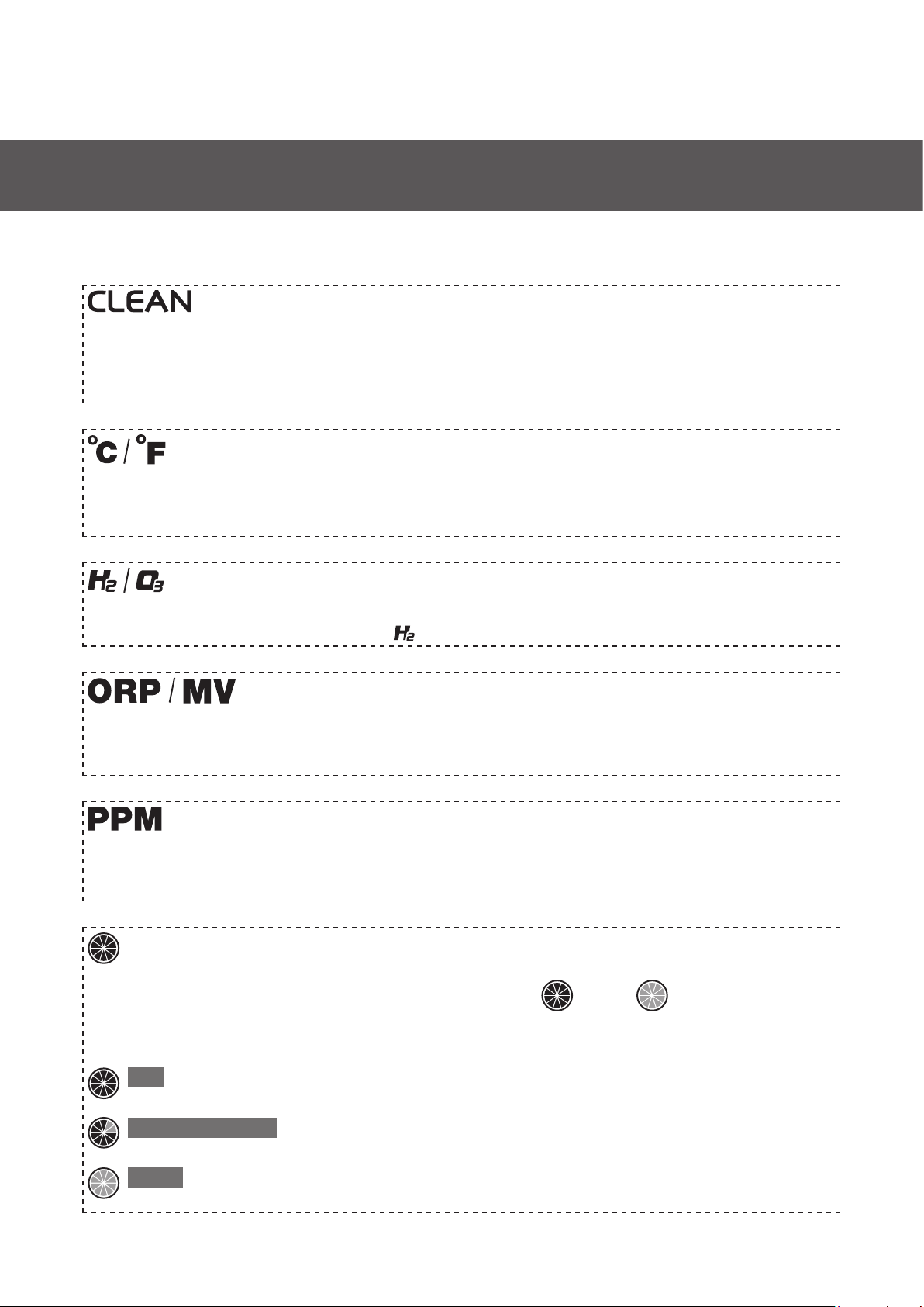
System Temperature
System’s temperature is measured and displayed during normal standby for user’s reference. Standard display is
in Degrees Celsius; Degrees Fahrenheit is optional. Please consult technician for setting.
Output Feature Indicator
Lighting up when specic function is selected. blinks during drinking pre-ush.
Parts Per Million Display
PPM stands for Parts Per Million (or mg/L), referring to the relative dissolved ozone concentration of the ozone
water output.
Oxidation-Reduction Potential Display
ORP stands for Oxidation-Reduction Potential, expressed in "mV" (millivolts), referring to the relative anti-oxidation
power of the hydrogen water output.
Ozone Performance Meter
The performance icon shows the performance charge level, from full to empty when using continuously,
filling to full in standby. When the meter shows that every segment is filled, the system is ready with peak
performance on standby.
Performance at peak
Full
Consuming or recharging performance
Vanished/Appeared
Performance at baseline
Empty
Internal Cleaning Indicator
CLEAN shows that the system is processing internal cleaning. All functions are suspended and little noise is normal
during this cleaning period. This function is available both for automatic and manual. In manual mode the water
will be discharged from the output. (P.22)
9

Installation
Power Disconnection Warning
Service Notication
Call customer service notication
Phase 1 - Within allowed power disconnection limits :
This icon is displayed when:
•
•
Phase 2 - Exceeding allowed power disconnection limits :
•
Displayed together with accumulated power off times.
- Service due.
- Error detected.
Displayed together with ERROR (E75) and accumulated power off times (Disconnection reached 72
times or more).
Service due in 3 weeks. Check service code(s).
Blink
Service due, functions suspended. Check service code(s).
On
•
•
• •
•
•
Metering life-cycle consumption for :
- iEOG module(Left)
Blinking when :
- Showing Power Disconnection Warning
- Exceeding power-off limits (equivalent to E75 code).
- Pre-filter(Right)
Disinfection
•
Ozone Water Motion
Sensor
Drinking
•
Hydrogen Water
Button
Full
Empty
Level Indicator
10

Installation
How to Install the Unit
Consult your local Biolux dealer for installation arrangements. The information described below in this section is
intended for user’s reference.
The most common configurations for home kitchens are discussed here. For additional installation options or
questions on your specic installation, please contact your regional Biolux service provider.
Tool You Will Need
Plumbing and Installation Instructions
A typical scheme for installation of HOS is shown below. Please follow all local plumbing and construction codes in
setting up the unit and all required water input, output and drain plumbing in accordance with the scheme.
Diverted Water Line
Isolation
Valve
Pre-Filter
Output
DrainCold Water In
Main Water Line
11

Installation
Typical Scheme of Installation
1. Unit location and setup
2. Locate a source for input water
3. Setup input water pre-lter
4. Connect input water and drain hoses
5. Setup and connect the water output
Instruction 1 – Counter-top or Wall-mount Installation Overview
Determine if you will place your unit simply on a stable counter or mount it on a wall near and above a sink. To
mount the HOS, please follow the directions below:
1. Drill two 6 mm holes with 30 mm in depth in the wall 400 mm above the top of the sink or counter. The
distance between the 2 holes must be 100 mm.
2. Press the plastic anchor inserts into the holes as pictured below. Push the plastic anchor insert so that the
opening is ush with the wall.
3. Place the mounting bracket on the wall and x with screws as pictured below. Hang the unit on the mounting
bracket.
Hanging Grooves
100mm
400mm
6mm
12
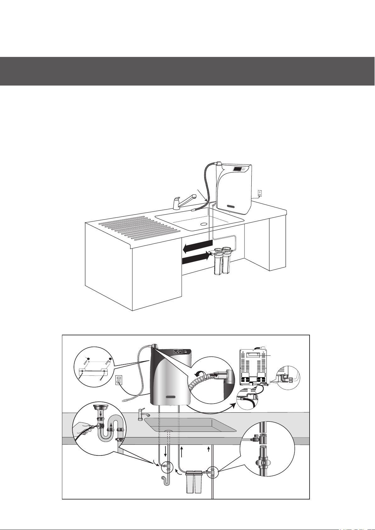
Important:
Installation
For counter-top installation, two 10 mm holes on the counter will be required for passing the input water and drain
hoses through the surface. This is in order to allow the connections from the back of the unit to under sink area for
input water and drain.
Below drawing shows the installation and relevant plumbing as installed with a counter-top scheme:
100mm
PS. before U trap
Hanging
Grooves
10mm holes x2 110~240V
Connect to drain
Tap water input
6mm
13

Installation
For under-counter installation, a digital sensor faucet designed exclusively for the unit will be required in order to
accomplish the control of output from counter-top. The HOS main device will be located under the sink. While the
connections of the input water and drain are accessible directly under the sink, the outlet will be connected to the
faucet for output.
Below drawing shows the installation and relevant plumbing schemes for under-counter installation:
Input Water
Hose
Drain Clamp
PS. before U trap
Faucet
Signal
Connection
AC Power
110~240V
Output
Hose
Input
Drain
Cold
Water
T-Adapter
Pre-Filter
Digital Sensor Faucet
(SF-100)
Existing Faucet
14
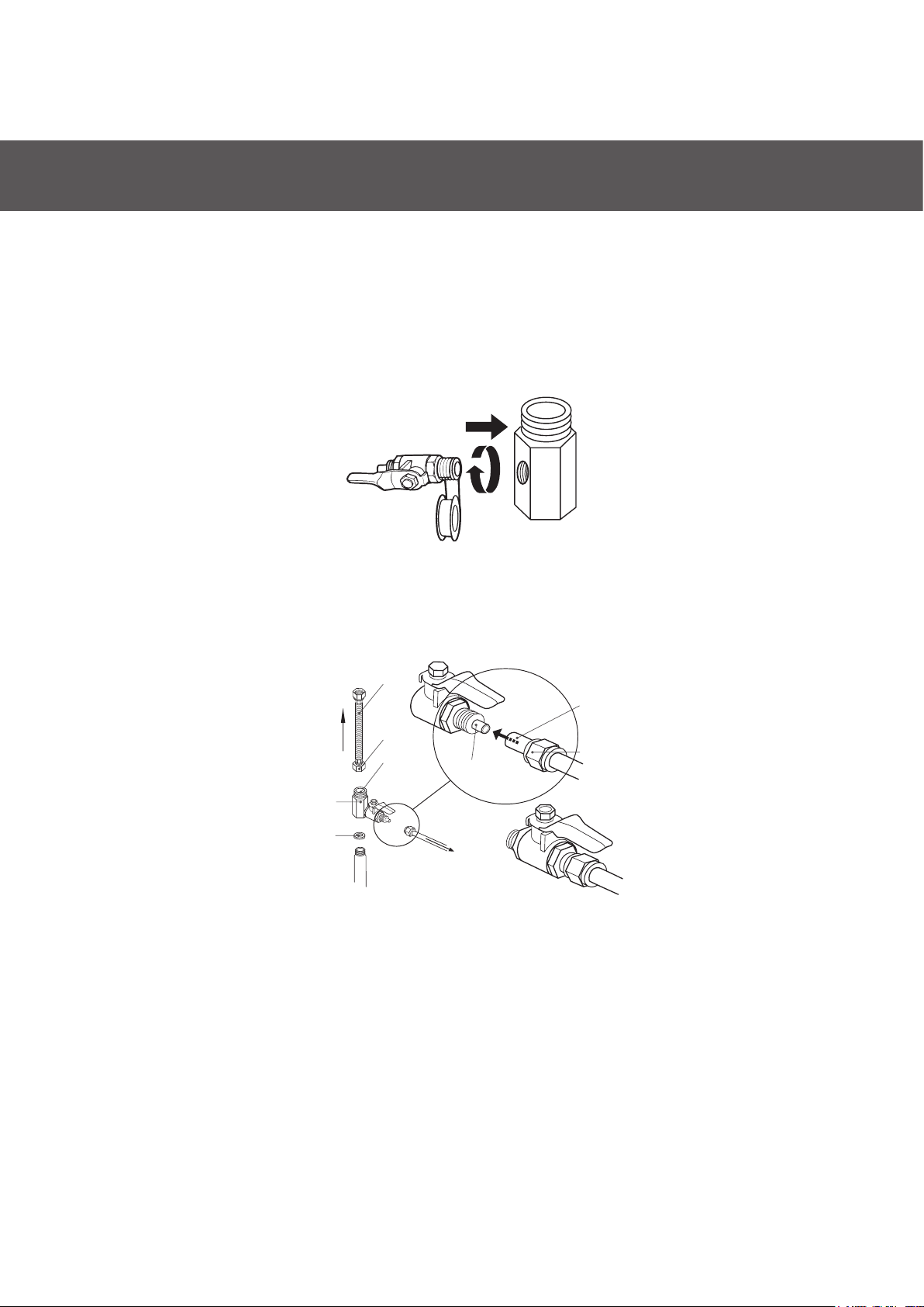
Instruction 2 – Input Water Setup
Installation
Find the ½" to ⅜" Ball Valve T-Adapter (diverter & valve) in the accessory box. Assemble and seal the threaded
connection with the plumber’s tape included in the accessory box:
1.
Instruction 3 – Setup Input Water Pre-Filter
Select an easy-to-access location and install your input water pre-lter between cold water supply and the unit (ex.
under the sink). It should be noted that after ltration water quality must meet your local standards for drinking
water requirements.
Locate the cold water supply under the sink. Shut off water supply.2.
Connect the adapter to the cold water line between the wall and the sink faucet as follows:3.
Connect the unit to the cold water line with input water pre-lter in between.4.
Input hose
Screw anchors
Washer
Diverter & Valve
To your existing faucet
Water ow direction OD 1/2"
ID 1/2"
15

Installation
Instruction 4 – Input & Drain Connection
Remove the joint tube from the unit’s inlet and outlet ttings on the back of the unit. This joint tube is used for
shipping purposes only.
1.
Find the input hose (white) and drain hose (black) in the accessory box.2.
Insert the input hose into the unit’s tting (COLD WATER IN). Tightly screw the nut onto the tting to secure the
hose into place. Then, attach the drain hose to the unit’s drain tting (DRAIN).
3.
For counter-top installation, two 10 mm holes on the counter will be required for passing the input water and
drain hoses through the surface.
4.
Setup the drain hose under-sink connection:
Drill a 10 mm hole into the sink drainpipe and install the drain hose with the drain clamp (included accessory)
in accordance with the below scheme.
5.
Insert and lock the Input water hose (white) into
“COLD WATER IN” fitting (white). Attach the drain
hose (black) to “DRAIN” tting (black).
PS. before U trap
16

Installation
Instruction 5 – Connect Water Output
To locate the water outlet, remove the plastic cap positioned at the top of the unit (rotating water output cap).
b. For under-counter installation, install the SF-100 Digital Sensor Faucet and connect it with HOS
according to the following instructions:
1. Drill a ϕ32 (mm) or 1 ¼”hole in the sink or counter top or use the available hole.
2. Insert the faucet tailpieces with supply and connection line into the hole.
3. From beneath the sink or counter top, screw the lock nut onto the faucet tailpieces and
tighten them with a basin wrench.
Digital Sensor Faucet (SF-100)
Counter top
Lock nut
3/8” tube
1.
LOCK
OPEN
a. For counter-top installation, nd the exible water outlet tube in the accessory box. Screw the
tube anticlockwise into the water outlet until there is no gap. Do not over tighten.
❶
❷
❸
❹
17

Installation
Connect the faucet and under counter unit and wire the waterproof connectors.
Connect the faucet and under counter unit and assemble the tubing as shown.
4.
5.
Waterproof connector
to faucet
Waterproof connector to under
counter unit
❺
❻
8
7910
❼
Unit water outlet cap
❼
Faucet adapter and union
converts M14 anti-clockwise
thread to M14 clockwise (use
the M14 anti-clock wise thread
to connect to the unit water
outlet cap)
❽
Ferrule (for 7x9 mm tube)
❾
M14 lock nut
❿
❽❾❿
18

Operation & Use
Unit Start-Up
Conrm all below points prior to start-up:
The following sequence of steps must be followed for manual shut-down:
The unit is switched ON by plugging the cord into wall outlet (power supply). There is no ON/OFF control switch.
Before plugging unit into wall outlet, all plumbing works should be completely set up.
The HOS is intended for constant power-on, unless in necessary situations, such as before machine servicing
activities.
The unit can be switched OFF by un-plugging the cord from wall outlet (power supply). Before shutting down the
unit, the water supply to the unit should be completely turned off.
To use the machine at the rst time, connect the unit to power to switch on and the system preparing indicator
“ ” will light up on the display panel. At this point, the unit is in preparation stage relling water for iEOG
start-up. This process will take about 30~55 minutes according to water pressure.
Note: Draining during this stage is normal.
Once this preparation phase is complete, the “ ” will go out automatically, and “ ” will light up,
indicating the unit is now ready for use. At this point, the panel displays the detected internal system temperature
on the display panel, too.
All inputs, output and drain are correctly installed to their corresponding connections.1.
Shut off water supply.1.
Ensure that the unit is connected to cold water supply input.2.
Turn off the system by un-plugging the cord from the wall outlet.2.
The power supply meets the requirements as indicated in the product specications.3.
Input water pressure is 2.0~7.0 kg/cm2 (29~100psi).4.
The area of operation is well ventilated.5.
Connection Check
Initial Start-Up
Conditionally Shut-Down
Re-Start & 30 Minutes Re-Start Protection
Note: Disconnecting the power frequently may cause unexpected impacts on the iEOG module and result in
degradation to the product performance. 72 times of power off in a year will void warranty.
To re-start the unit, connect the unit to power to switch on. In system re-starting, all functions are suspended for
30 minutes along with “ ” ashing slowly (blink/0.5 sec). During this waiting period, maintenance program
is running at background for self-check.
19
Table of contents
Other Bio-Tek Water Filtration System manuals


Popular Water Filtration System manuals by other brands

WilTec
WilTec NW-RO50-C1 Operation manual

A.O. Smith
A.O. Smith AO-US-200 owner's manual

Clean Water Systems
Clean Water Systems Fleck 9100 Installation & start?up guide

Water Factory Systems
Water Factory Systems SQC3 Series owner's manual

GRE
GRE FS550 Installation and maintenance manual

CSI
CSI UTP15-S2 Installation and operation manual


