Water Factory Systems SQC3 Series User manual

SQC Series
Owner's Manual
This Manual is for the Installation, Operation,
and Maintenance of the
WATER FACTORY SYSTEMS™
SQC3 and SQC4 Series
Reverse Osmosis (RO) Drinking Water Appliance
™
Installer: Leave with homeowner.


SAFETY INFORMATION
Read, understand and follow all safety information contained in these instructions prior to instal-
lation and use of the SQC Series Reverse Osmosis (RO) Drinking Water Appliance. Retain these
instructions for future reference.
Intended use:
The Water Factory Systems™ SQC Series Reverse Osmosis (RO) Drinking Water Appliance is intended to
connect permanently to a home plumbing system and has not been evaluated for other uses.
EXPLANATION OF SIGNAL WORD CONSEQUENCES
WARNING
Indicates a potentially hazardous situation, which, if not avoided, could result in death or serious
injury and/or property damage.
CAUTION
Indicates a potentially hazardous situation, which, if not avoided, may result in property damage.
CAUTION
Indicates a potentially hazardous situation, which, if not avoided, may result in minor or moderate
injury and/or property damage.
To reduce the risk associated with choking:
• Donot allow children under 3 years of age to have access to small parts during the installation of this
product.
To reduce the risk of physical injury:
• Allhydro-pheumaticpressurizedtanksmusthaveanappropriatepressurereliefvalveinstalled.
• Shutoffinletwatersupplyanddepressurizesystemasshowninmanualpriortolterremoval.
To reduce the risk associated with the ingestion of contaminants:
• Donot use with water that is microbiologically unsafe or of unknown quality without adequate disinfection
beforeorafterthesystem.Systemscertiedforcystreductionmaybeusedondisinfectedwaterthatmay
containlterablecysts.EPAEstablishmentNumber070595-CT-001.
•AnapprovedairgapmustexistbetweentheROSystemrejectdrainlineandthedrainlineopeningtomeet
plumbing codes.
To reduce the risk associated with irritation from Sodium Metabisulfite during installation:
• SodiumMetabisulte(CAS07681-57-4)isusedina1%preservativesolutionwithinthereverseosmosis
membrane.
• DonotputthissystemintoservicebeforetheROtankisushedasspeciedintheinstallationinstruc-
tions. Wear eye and face protection during installation.
• TorequestanMSDSrelatingtothisproduct,call203-238-8965orvisitthewebathttp://solutions.3m.
com/wps/portal/3M/en_US/MSDS(clickMSDSsearch).Foremergencies,call800-364-3577or651-737-
6501(24hours).
To reduce the risk associated with eye, skin and respiratory and digestive tract burns from Calcium Hypochlorite
during installation:
• CalciumHypochlorite(CAS7778-54-3)granulesareusedfortanksanitationinthisproduct.
• Duringinstallation,donotgetineyes,onskinorclothing.Donotingest.Weareyeandfaceprotection.
Keep out of reach of children.
• TorequestanMSDSrelatingtothisproduct,call203-238-8965orvisitthewebathttp://solutions.3m.
com/wps/portal/3M/en_US/MSDS(clickMSDSsearch).Foremergencies,call800-364-3577or651-737-
6501(24hours).
To reduce the risk associated with ingestion of water contaminated with sanitizer:
• Sanitizermustbeushedfromthesystembeforeusingasdirectedwithintheinstallationinstructions.
To reduce the risk associated with hazardous voltage due to an installer drilling through existing electric wiring or
water pipes in the area of installation:
• Donot install near electric wiring or piping which may be in path of a drilling tool when selecting the posi-
tiontomountthelterbracket.

To reduce the risk associated with property damage due to water leakage:
• Read and follow UseInstructionsbeforeinstallationanduseofthissystem.
• Installationanduse MUST comply with all state and local plumbing codes.
•
Protect from freezing,removeltercartridgewhentemperaturesareexpectedtodropbelow40°F(4.4°C)
.
•
Donotinstallsystemsinareaswhereambienttemperaturesmaygoabove110°F(43.3°C)
.
• Donotinstallonhotwatersupplylines.Themaximumoperatingwatertemperatureofthisltersystem
is100°F(37.8°C).
• Donotinstallifwaterpressureexceeds100psi(690kPa).Ifyourwaterpressureexceeds80psi(552
kPa),youmustinstallapressurelimitingvalve.Contactaplumbingprofessionalifyouareuncertainhow
to check your water pressure.
•
Donotinstallwherewaterhammerconditionsmayoccur.Ifwaterhammerconditionsexistyoumustinstalla
water hammer arrester. Contact a plumbing professional if you are uncertain how to check for this condition.
•
Wherebackowpreventiondeviceisinstalledonawatersystem,adeviceforcontrollingpressuredueto
thermalexpansionmustbeinstalled.
• Donotuseatorchorotherhightemperaturesourcesnearltersystem,cartridges,plasticttingsor
plastic plumbing.
• Onplasticttings,neverusepipesealantorpipedope.UsePTFEthreadtapeonly, pipe dope properties
may deteriorate plastic.
• Takecarewhenusingpliersorpipewrenchestotightenplasticttings,asdamagemayoccurifovertight-
ening occurs.
• Donotinstall in direct sunlight or outdoors.
• Allhydro-pneumatictanksmusthaveanappropriatepressurereliefvalveinstalled.
• Donot install near water pipes which will be in path of a drilling tool when selecting the position to mount
the bracket.
•
Mountlterinsuchapositionastopreventitfrombeingstruckbyotheritemsusedintheareaofinstallation.
• Ensurethatthelocationandfastenerswillsupporttheweightofthesystemwheninstalled.
• Ensurealltubingandttingsaresecureandfreeofleaks.
•
Donotinstallunitifcolletismissing.ContactWaterFactorySystemsifcolletsaremissingfromanyttings.
• SHUTOFFFUELORELECTRICPOWERSUPPLYTOWATERHEATERafterwaterisshutoff.
• ThedisposableltercartridgeMUST bereplacedevery12months,orsoonerifanoticeablereductionin
owrateoccurs.
• TheROMembranecartridgeMUST bereplacedatleastevery36months.
To reduce the risk of eye injury while drilling counter-tops for faucet installation:
•Safety glasses MUST be worn during the sink hole drilling operations.
To reduce the risk of eye injury while drilling counter-tops for faucet installation:
•Safety glasses MUST be worn during the sink hole drilling operations.
To reduce the risk of injury associated with household bleach:
•Read and follow manufacturers directions and cautions
•Keep out of the reach of children
• DONOTintermixwithotherchemicals
• Failure to install, operate, or maintain your drinking water appliance in accordance with
these use instructions or any other installation or use instructions accompanying this
product may result in product failure and property damage, including water leakage and
will void warranty.

INTRODUCTION
This manual explains the installation, operation and maintenance of the Water Factory
Systems™SQC Series Reverse Osmosis (RO) Drinking Water Appliances. Please read each
section of this manual carefully. The specific model chosen should be appropriate for the
local water conditions and the customer’s needs. Check the Performance Data Sheet for the
performance characteristics and the conditions of use.
The Water Factory Systems undercounter RO drinking water appliances are designed to
connect permanently to a home plumbing system. To ensure that the installation conforms to
your state and local plumbing codes, it is recommended that the installation be performed by a
qualified installation specialist for RO drinking water appliances or a licensed plumber. Failure
to install the system as instructed will VOID the warranty.
TABLE OF CONTENTS
I. Installation Instructions
A. Determine the appliance location................................................................................... 3
B. Prepare the area for installation ..................................................................................... 3
C. Prepare the appliance for installation............................................................................. 4
D. Make the faucet mounting hole ...................................................................................... 4
E. Mount the faucet............................................................................................................. 5
F. Install Stem Adapter With 1/4” Feedwater Tube Outlet ................................................. 6
G. Prefill and sanitize the storage tank ............................................................................... 6
H. Install the drain connection............................................................................................. 7
I. Install the filtration assembly and storage tank .............................................................. 7
J. Make the tubing connections.......................................................................................... 8
K. Install the icemaker hookup (optional) ........................................................................... 8
L. Start up the appliance .................................................................................................... 8
M. Flush the appliance of the preservative and check the operation.................................. 9
N. Cleanup & paperwork..................................................................................................... 9
O. Appendix for basement installations............................................................................... 11
P. Installation troubleshooting............................................................................................. 12
II. Operation & Maintenance Instructions
A. Important water quality assurance requirements ........................................................... 13
B. Replacing the filter cartridges......................................................................................... 13
C. Replacing the RO membrane cartridge.......................................................................... 13
D. Sanitizing the RO appliance........................................................................................... 14
E. Long term non-use ......................................................................................................... 15

A. DETERMINETHEAPPLIANCELOCATIONS
The appliance can be located under a sink or in a base-
ment depending on space availability and the customer’s
preference. If a basement installation is selected, additional
tubing, hardware and fittings may be needed and a hole will
have to be made from inside the cabinet, through the floor, to
the basement. Never install it in an area of the home where
the temperature may drop below 40
°
C, because damage to the
appliance may occur.
The exact placement of the various components of the
appliance will vary from installation to installation. The install-
er, in conjunction with the customer, must decide on where to
place the faucet, tank and filtration assembly by balancing the
homeowner’s convenience with ease of installation and servic-
ing. (See Fig. 1 & 7)
Considerations for an icemaker or other remote hookup
should be predetermined, including routing and any additional
tools, fittings, and tubing that may be required.
B. PREPARETHEAREAFORINSTALLATION
Remove supplies from under the sink and stack them
neatly away from the working area. Arrange a light for the work
area, if necessary.
If a basement installation is called for, determine where
the components will be located and how they will be mounted.
Special mounting brackets and hardware may be necessary to
secure the appliance to a wall or ceiling joists. (See Figure 7)
Inspect the cold water supply line and determine if any
special fittings, in addition to what is included in the kit, are
required.
NOTE: It is a good idea at this time to check the condition of
the undercounter plumbing for any existing or potential leaks.
Make sure to perform any necessary repairs prior to the instal-
lation of the drinking water device.
I. Installation Instructions
3
Fig. 1
Drain
Saddle
SinkDrain
Storage Tank
Filtration System
1/4"Orange
Tubing
3/8" Yellow
Tubing
Pressure Relief Valve
(required, not included)
Storage Tank Valve
Red SFC Tubing
1/4" Green
Tubing
Feedwater
Connection
Placement
3/8" Blue
Tubing
3/8" Black
Tubing
Reducing
Union
C. PREPARETHEAPPLIANCEFORINSTALLATION
Open the shipping carton and remove the components.
Check to see that all of the installation parts are present. They
should include the filtration assembly, storage tank, faucet,
installation hardware, RO membrane, cartridges and tubing.
Check to see that the air supply in the empty tank is approxi-
mately 7 psi (48 kPa). Adjust it if necessary. To reduce the
risk of cartridge contamination, the RO membrane cartridge
has been shipped separately in a sealed plastic bag. Follow
the steps below to install the RO membrane cartridge.
STEP 1: Cut open the sealed plastic bag and remove the RO
membrane cartridge.
STEP 2: Remove the white plug from the fitting at the bottom
of the cartridge by pushing in the small gray collet and pulling
out the plug simultaneously (see Figure 6).
STEP 3: Connect the red SFC reject tubing by inserting the
open end into the fitting at the bottom of the RO membrane
cartridge as far as it will go. Take note of the tag attached to
the SFC tube which indicates the outlet end.
STEP 4: Remove the red plastic cap from the top of the car-
tridge.
STEP 5: Line up the cartridge ears (Fig. 8), insert the cartridge
and push it into the head until it is fully seated. Twist the
cartridge 1/4 turn counterclockwise to lock it into place. The
final orientation should be such that the cartridge label faces
towards the front and the fitting is located towards the rear.
D. MAKETHEFAUCETMOUNTINGHOLE
A wide variety of RO faucet mounting situations may be
encountered. The most common are stainless steel or ceramic
on metal sinks. Consult your dealer for any other materials
which may be encountered. The faucet should be positioned
so that it empties into the sink and the spout swivels freely for
convenience. If the sink already has a hole provided that can
accommodate the RO faucet, then no drilling is required.
To reduce the risk of eye injury while drilling counter-tops
for faucet installation:
• Safety glasses MUST be worn during the sink hole drilling op-
erations.
IMPORTANT NOTE
• Ifdesired,sprayerscanbedisconnectedtoprovideasuit-
able mounting hole for the RO faucet. A pipe cap or plug
will be required to seal the sprayer connection.
Before drilling the hole, always check underneath the sink to
ensure that nothing will interfere with mounting the faucet such
as reinforcing ribs, support brackets or the cabinet construction.
Stainless steel sink, air gap or non-air gap faucet.
Recommended tools:
• Centerpunch
• Variablespeeddrillandhighspeeddrillbits
• Greenlee7/8”chassispunch(alternate9/16”
may be used for a non-air gap faucet)
• Protectivegloves
Procedure:
1) Center punch a small indent at the center of
the desired faucet location.
2) Slowly drill the required pilot hole for the
chassis punch.
3) Set up the chassis punch per the instructions and
tighten the nut to cut the desired hole size.
4) Clean up all sharp edges with a file if necessary.
Porcelain/Enamel/Ceramic sink on sheet metal or cast iron
base; air gap or non air gap faucet.
Recommended tools:
• Variablespeeddrill
• Relton7/8”porcelaincuttertoolset(alternate9/16”
porcelain bit may be used for a non-air gap faucet)
• Plumber’sputty
It is important to understand what is involved in this proce-
dure. First, the glassy layer of porcelain must be penetrated
through to the base metal. Second, a center disc of porcelain
must be removed while protecting the surrounding porcelain
against chipping or fracturing. Third, the base metal must be
drilled through to complete the hole.
Procedure:
1) Mark the center for the 7/8” hole.
2) Form a shallow putty dam around the hole area and fill it
with enough water to lubricate the carbide drill bit.
3) Carefully drill a pilot hole through the porcelain/enamel and
the base metal using a carbide type pilot drill.
Important: Always operate the drill with light bit pressure
at a slow speed (300-400 rpm).
4) Insert the pilot tip of the spring-loaded porcelain cutter into
the pilot hole.
5) Drill the porcelain/enamel using the spring-loaded porcelain
cutter, making certain a complete ring has been cut through
the porcelain/enamel to the metal base.
6) Change to the metal cutter. With a slow speed and light
pressure, cut away the inner porcelain/enamel disc down
to the base metal. Make certain that the cutter does not
touch the outer rim of the cut porcelain/enamel. Continue
with this bit to cut completely through the metal.
IMPORTANT NOTE
• When using a porcelain cutter it is critical that it is always
in a sharpened condition. Dull cutters are known to chip
sinks.
Drilling 7/8” diameter hole through countertop or stainless steel sink:
1. Locate area to be drilled. Mark center of hole with center
punch.
2. Drill hole with 7/8” drill bit suitable for countertop materials or
cast iron/stainless steel.
3. With grinding wheel or file, smooth out any rough edges.
4
E. MOUNTTHEFAUCET
Undercounter installations generally require that the
faucet’s built-in air gap be used. In basement installations,
the built-in air gap does not have to be used if one is provided
elsewhere on the drain line.
For Basement Installations Without An Air Gap Module
See Installation Instructions on page 11.
IMPORTANT NOTE
• The Uniform Plumbing Code dictates that there must be
an air gap between the RO reject line and the waste drain.
An optional non-air gap faucet, which requires a smaller
9/16” mounting hole, is available to make basement in-
stallations easier.
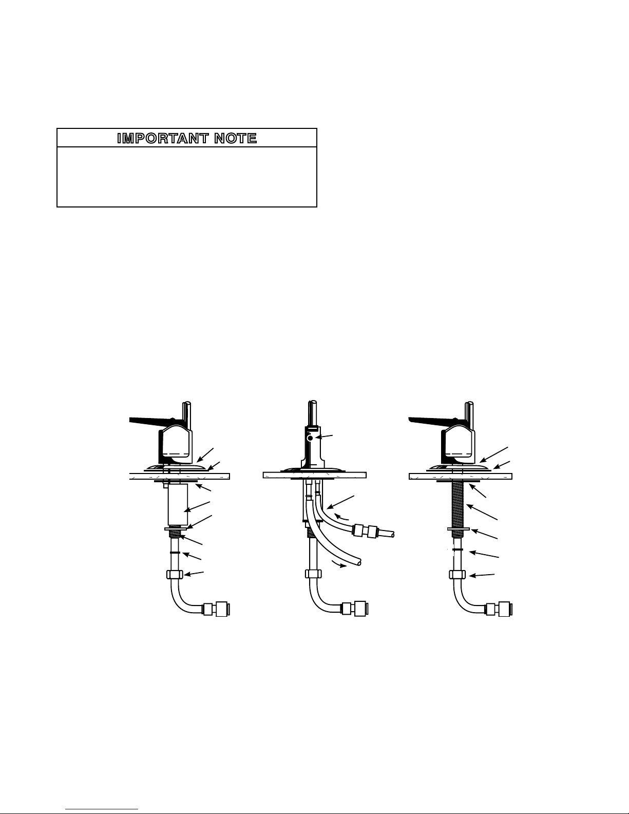
Undercounter Installation With An Air Gap Faucet:
1) Familiarize yourself with all of the components shown in
the air gap faucet diagram. (See Fig. 2)
2) Remove 3/8” tubing in front of the black faucet handle and
discard. Push faucet spout into where the 3/8” tubing was
just removed.
3) Slide the chrome base plate and rubber washer up the
threaded base of faucet.
4) Connect the 1/4” green tubing supplied in the installation kit
to the smaller barb on the air gap faucet. Push it on firmly
until it seats.
5) From above the sink counter-top, feed the air gap tubing
and the threaded nipple through the faucet mounting hole
and position the faucet spout over the sink.
6) From below the sink/countertop, install the white spacer
(open side toward the air gap tubing), flat washer, lock wash
er and hex nut onto the threaded nipple and tighten it by
hand.
7) Back off on the hex nut just enough to slide the slotted
washer (open side toward the air gap tubes) between the
white spacer and the underside of the sink/countertop.
8) After rechecking the faucet orientation, tighten the hex nut
with a 9/16” wrench until the faucet feels secure.
9) From above the sink, make any minor orientation corrections
by turning the faucet on its flats with a padded adjustable
wrench. Use care so as not to mar the chrome finish.
5
C.L.
FaucetwithAirGap FaucetwithoutAirGap
Side View Back View Side View
Chrome base plate
AirGaphole
1/4”Standard
green tubing
Specialred“SFC”
tube from RO
Black3/8”Reject
tubing to drain
Blue3/8”Product
water tubing connection
Blue3/8”Product
water tubing
Rubber washer
Plasticbottomwasher
Threaded nipple
Flatwasher
Lockwasher
Hexnut
Blue3/8”Product
water tubing
Chrome base plate
Rubber washer
Threaded nipple
Flatwasher
Spacer
Hexnut
Slotted washer
Fig. 2
1/4”x3/8”TubeConnector 1/4”x3/8”TubeConnector 1/4”x3/8”TubeConnector
Lockwasher
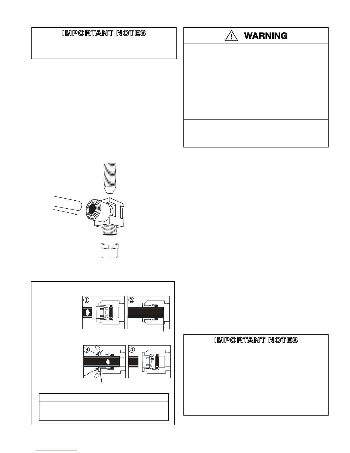
F. INSTALLSTEMADAPTERWITH1/4”FEEDWATER
TUBEOUTLET
IMPORTANT NOTES
• For basement installations, the existing orange feed
water tubing may have to be longer to reach the faucet
adapter.
1) Open faucet and turn off cold water supply to relieve pres-
sure.
2) Locate the cold water stem on the underside of the faucet
fixture. Unscrew the cold water feed tube from the faucet
stem. Locate the Faucet Adapter that came with your drink-
ing water system. Insert the black gasket into the threaded
adapter and tighten onto the Faucet Cold Water Stem under
the sink, making sure that 1/4” side connection is accessible
and not facing the wall. Make sure not to overtighten.
3) Take the Cold Water Feed Tube and attach to the Faucet
Adapter, making sure not to over tighten.
4) Locate the 1/4” Orange Tubing and insert into the 1/4”
outlet of Faucet Adapter. See Figure 3 and “Using Push-in
Fittings” below.
5) Leave cold water supply off.
G. INSTALLATIONSANITIZING*
PREFILLANDSANITIZETHESTORAGETANK
To reduce the risk associated with eye, skin and respiratory and di-
gestive tract burns from Calcium Hypochlorite during installation:
• CalciumHypochlorite(CAS7778-54-3)granulesare
used for tank sanitation in this product.
• Duringinstallation,donotgetineyes,onskinor
clothing. Do not ingest. Wear eye and face protection.
Keep out of reach of children.
• TorequestanMSDSrelatingtothisproduct,call203-
238-8965orvisitthewebathttp://solutions.3m.com/
wps/portal/3M/en_US/MSDS(clickMSDSsearch).For
emergencies,call800-364-3577or651-737-6501(24
hours).
To reduce the risk associated with ingestion of water contaminated
with sanitizer:
• Sanitizermustbeushedfromthesystembefore
using as directed within the installation instructions.
Prefilling the storage tank is always recommended so that there
is pressure to check for leaks as well as sufficient water to flush
the carbon postfilter. The SQC RO Drinking Water Appliance
is furnished with a container of special sanitizing granules. It is
important to use a sanitizer when prefilling the tank.
1) Remove protective cover from storage tank and discard.
Locate the enclosed container of sanitizing granules, open
it and pour the contents into the end of the tank. Apply PTFE
tape (not included) to threaded tank connection and install
tank valve onto connection. Do not over tighten. Open the
tank valve so that the tank valve handle is parallel to the
valve body.
2) Disconnect the 3/8” yellow tubing from the back of the
filtration assembly and connect one end of it into the tube
fitting located on the tank valve.
3) Connect the other end of the 3/8” yellow tubing to the 3/8”
x 1/4” union connector included in the tank sanitization kit.
4) Connect the free end of the 1/4” orange feed water tubing
to the other end of the 3/8” x 1/4” union connector.
5) Open the cold water supply shut off valve (making sure the
tank valve is still open) and allow the tank to fill (about
3 minutes).
6) Close the cold water supply shut off valve and the tank valve.
Disconnect the 3/8” yellow tubing from the tank valve elbow
fitting and set the tank aside while proceeding with the rest of
the installation (the sanitizatizing solution should be kept in the
tank for at least 15 minutes).
7) Reconnect the 3/8” yellow tubing to the back of the
filtration assembly. Reconnect the 1/4” orange tubing to
the feed water fitting on the filtration assembly.
IMPORTANT NOTES
• If you encounter difficulty in removing the tubing from the
tank, make sure the tank valve is closed and then cut the
yellow tubing approximately 1” away from the tank valve
fitting to relieve the pressure. Remove the 1” piece from
the tank fitting.
• If an alternate storage tank is used, it should be sanitized
with household bleach (5-1/4%). Use 3 ml. (1/2 teaspoon)
of bleach for a 2.5 gallon tank.
• After the installation is complete, it is recommended that
the 3/8” x 1/4” union connector be saved for future use in
tank sanitization.
*ForYearlyOwnerMaintenanceSanitizingInstructions,seepage14
6
To Release Tubing
Push in grey collet to
release tubing. With
collet held, pull tubing
straight out.
Collet
Backstop
“Using Push-In Fittings”
To Attach Tubing
Push tubing in as
far as it will go.
Tubing must be
inserted past o-ring
and hit backstop.
Pull tube to ensure it is secured.
CAUTION
To reduce the risk associated with property damage due to
water leakage:
• Ensure all tubing and fi ttings are secure and free of leaks.
Fig. 3
Orange Tubing
Faucet Stem
Undersink
Feedwater
Tube
H. INSTALLTHEDRAINCONNECTION
IMPORTANT NOTES
• Before starting this procedure, inspect the condition of the
drain piping, especially in older homes where the traps
and tailpieces can be deceptively thin and frail. If they are
in poor condition, it is wise to inform the customer that the
condition should be remedied.
• Some local plumbing codes may prohibit the use of sad-
dle-type valves and/or drain connections. The use of
saddle-type valves are prohibited in Alaska, Delaware,
Idaho, Kentucky, Massachusetts, Michigan, Minnesota,
New Hampshire, North Dakota, Ohio, and South Dakota.
Check your local plumbing codes for any restrictions that
apply. Massachusetts CMR 248 strictly prohibits the use
of saddle-type valves. The feed water connection must
conform to applicable plumbing codes.
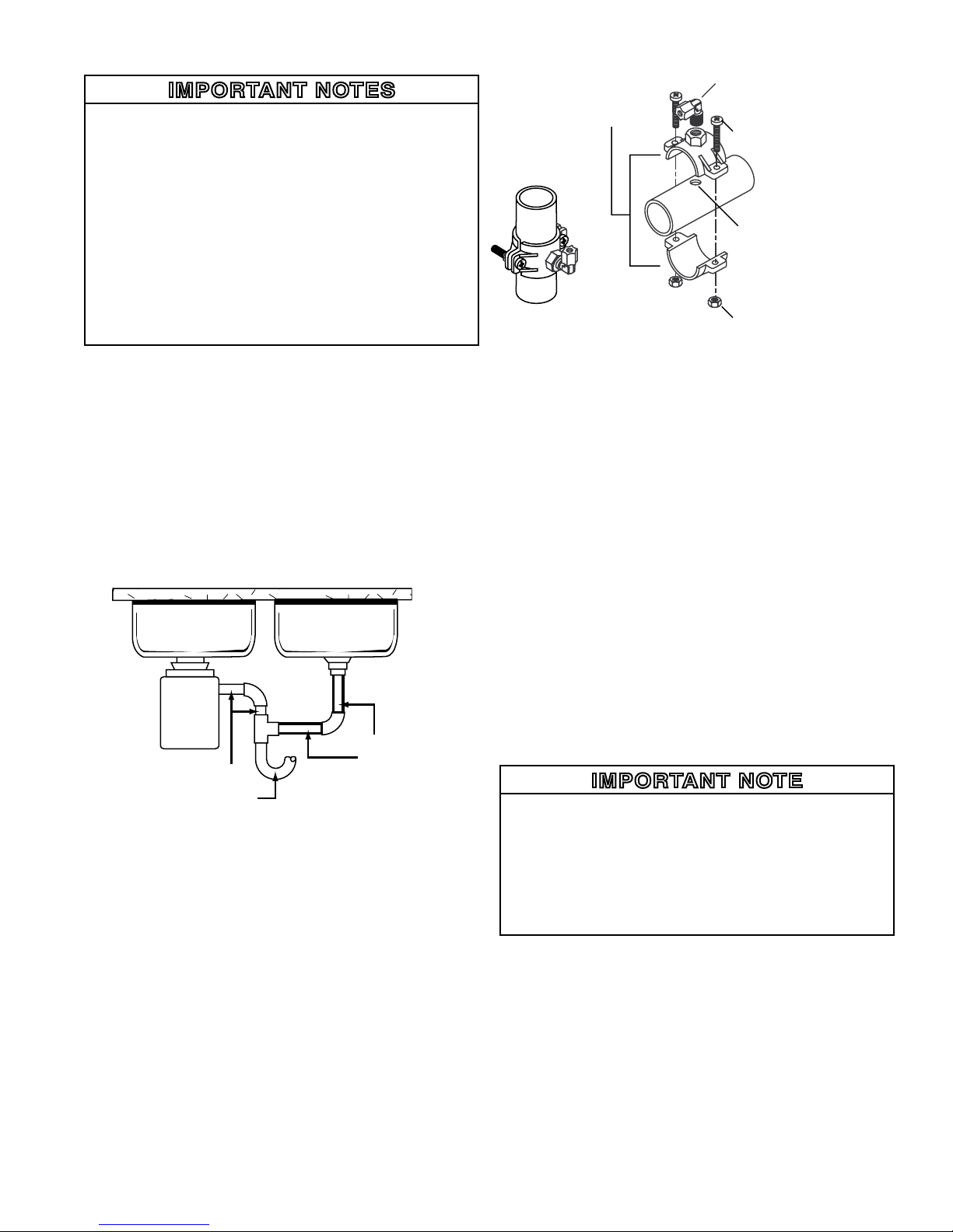
Undercounter Installation:
The drain saddle assembly is designed to fit around a
standard 1-1/2” OD drain pipe. For smaller (lavatory type) or
larger (ABS pipe) drains, consult your dealer for special drain
saddles.
The drain saddle should always be installed above (before) the
trap and on the vertical or horizontal tailpiece. Never install the
drain saddle close to the outlet of a garbage disposal because
plugging of the RO drain line may occur. (See Fig. 4)
1) Remove backing on foam seal and place over hole on
threaded half of the drain saddle. Place drain saddle at
the selected location and mark the pipe through the thread
ed opening.
2) Drill a 1/4” hole at the marked location through one side of
the drain tailpiece.
3) Position both halves of the drain saddle on the drain pipe
so that the threaded opening is lined up with the hole in
the drain pipe.
4) Use the screws and nuts to clamp the drain saddle onto
the drain pipe. Make sure that there is equal space
between saddle halves on each side. Do not overtighten.
(See Fig. 5)
5) Orient the elbow in the direction of the RO faucet location.
I. INSTALLTHEFILTRATIONASSEMBLYAND
STORAGETANK
For Basement Installation See Installation Instructions O.
Undercounter Installation:
The filtration assembly is usually mounted to the right or
the left side wall inside of the sink cabinet, taking into consider-
ationthespaceavailableandthetanklocation.Generally,the
storage tank is placed in the rear of the sink cabinet while the
filtration assembly is positioned toward the front for filter car-
tridge accessibility.
To mount the filtration assembly, elevate it at least 2” (5
cm) off of the cabinet floor and, while keeping it level, mark the
location of the mounting holes on the cabinet side wall. Make
small pilot holes with an awl or a drill and screw in the two
mounting screws; leaving just enough protruding to allow the
bracket mounting slots to slide over them.
IMPORTANT NOTE
•If the cabinet side walls are not of solid construction, the
filtration assembly can be set on the cabinet floor and held
against the side wall with the mounting screws. However,
the filtration assembly will then need to be lifted from the
mounting screws in order to remove the filter cartridges.
•It is essential that the filters be installed in the correct
location. Use the icon coded label to match the replacement
filters with their corresponding filter heads.
The storage tank may be oriented either vertically or horizon-
tally. It is generally placed to the rear of the cabinet but can
be set in the front center (between the sink basins) for ease
of access if space permits. For horizontal positioning, care-
fully detach the tank base from the tank bottom and use it as a
cradle.
7
MOUNT
HERE
NEVER
MOUNT
HERE
Fig. 4
Vertical Position Horizontal Position
Nut
Screw
DrainSaddle
Elbow
IMPORTANT:
Hole should be located on
top of the pipe if drain saddle
is positioned horizontally.
DrainSaddle
Halves
Fig. 5
GARBAGE
DISPOSAL

J. MAKETHETUBINGCONNECTIONS
With all of the components in place, the tubing connections
can be made. When routing the tubing between the compo-
nents, several guidelines should be observed.
• Tubingrunsshouldgenerallyfollowthecontourofthe
cabinet rather than interfere with the cabinet storage area.
• Striveforaneatandorderlytubing“flow”byusing
fasteners (e.g. insulated staples) to secure the tubing.
• Arrangethetubingsothattherearenosharpbends.
Leave some “play” in the tubing for ease of servicing, then
cut the tubing to the desired length.
• Trytokeepthetubingfromthefiltrationassemblytothe
tank and faucet as short as practical for good flow.
For Basement Installation See Installation Instructions O.
Undercounter Installation:
The appliance will have the 3/8” yellow and the 3/8” blue
tubing already connected to the filtration assembly.
1) The 1/4” orange tubing should already have been
connected to the cold water supply shut off valve.
Route the other end through the large opening in the “
bottom of the metal bracket and loop it back to the “Feed”
connection on the filtration assembly.
2) Attach the 1/4” x 3/8” union to 1/4” blue tubing on faucet.
3) Connect the 3/8” blue tubing from the filtration
assembly to the other end of 3/8” x 1/4” union.
4) Route the 3/8” black tubing from the faucet air gap to the
drain saddle so that it slopes continuously downward
without any loops or low spots. Cut the tubing to the
proper length and connect it to the drain saddle elbow.
5) Connect the 3/8” yellow tubing from the filtration
assembly to the tank.
6) Remove the plug from the elbow fitting on the RO module
cartridge. Insert the special SFC tube into this elbow fitting.
(Note: The elbow fitting is labeled “drain” on the RO
module.) Route the special red SFC tubing toward the
faucet. Do not cut this special SFC tubing. Its length is
important to maintain proper efficiency and performance.
7) Cut the 1/4” green tubing from the faucet air gap to the
proper length and connect it to the1/4” connector fitting on
the end of the SFC tubing.
K. INSTALLTHEICEMAKERHOOKUP(optional)
The RO drinking water appliance can be connected to any
standard refrigerator icemaker or icemaker/water dispenser. It
should never be connected to a commercial type bar icemaker.
Hooking up an icemaker involves connecting a tee with a
shut off valve into the 3/8” blue faucet tubing and routing the
tubing over to the refrigerator. Hooking up to existing copper
unit is generally not recommended unless it is less than six
months old. If copper tubing must be used, then the installa-
tion of a small in-line carbon filter at the refrigerator connection
is recommended.
Before turning off the existing tap water supply to the refrig-
erator icemaker, always shut off the icemaker first (usually by
lifting the lever arm above the bin to the uppermost position).
The icemaker should only be turned on again after the RO
system has been drained several times and the storage tank
has a full supply of water.
IMPORTANT NOTES
• Before any service is performed on the RO appliance, al-
ways turn off the icemaker valve and the icemaker unit.
Only turn them on when the system is operating and the
tank is full.
L. STARTUPTHEAPPLIANCE
1) Double check to see that all of the connections are secure.
2) Open the cold water supply shut off valve and check the
appliance for leaks. If any leaks are detected, close the
valve and correct the problem before proceeding.
IMPORTANT NOTE
If a leak occurs at a “Push In” plastic fitting, then refer to Fig. 6.
3) Open the storage tank valve and lift the faucet handle until
a steady stream of water flows. Close the faucet, wait at
least 5 minutes and carefully check for leaks. Correct
them as necessary.
IMPORTANT NOTE
When the appliance is first turned on, water may intermittently
“spurt” from the air gap opening at the side of the faucet. This
is perfectly normal, and is caused by air trapped in the sys-
tem. This will usually disappear within a short time.
8
This product is outfitted with user friendly ‘Push In’ connectors. Proper use of the
connectors is shown in Figure 3.
It is most important that the tubing selected for use with these connectors be of
high quality, exact size and roundness, and with no surface nicks or scratches. If it is
necessary to cut the tubing, use a plastic tubing cutter or sharp razor knife. Make a
clean square cut.
Should a leak occur at a ‘Push-In’ connector, the cause is usually defective tubing.
ToFix: •Relieve pressure
•Releasetubing
•Cutoffatleast1/4”fromend.
•Reattachtubing
•Confirmconnectionisleakfree.
‘Push-In’ Tubing Connector
Fig. 6

9
M. FLUSHTHEAPPLIANCEOFTHEPRESERVATIVE
ANDCHECKTHEOPERATION
1) With the tank valve closed (the tank should still contain the
sanitizing solution at this point), open the faucet (set the
faucet handle in the “up” position) and feed water valve.
Water should begin to drip from the faucet within several
minutes. Continue to flush the system for 24 hours. Water
will steadily drip from the faucet at this time. During this
procedure, the tank is being intentionally bypassed in
order to thoroughly sanitize the tank and also flush the
membrane of any preservatives.
To reduce the risk associated with irritation from Sodium Metabi-
sulfite during installation:
• SodiumMetabisulte(CAS07681-57-4)isusedina
1%preservativesolutionwithinthereverseosmosis
membrane.
• DonotputthissystemintoservicebeforetheRO
tankisushedasspeciedintheinstallationinstruc-
tions. Wear eye and face protection during installa-
tion.
• TorequestanMSDSrelatingtothisproduct,call203-
238-8965orvisitthewebathttp://solutions.3m.com/
wps/portal/3M/en_US/MSDS(clickMSDSsearch).For
emergencies,call800-364-3577or651-737-6501(24
hours).
2) After flushing for 24 hours, shut off the faucet. Open the tank
valve, lift the faucet handle again and allow the tank to
completely empty. When the tank is empty, the faucet will
drip steadily. Measure and record the rate at which water
drips from the faucet. Use a graduated cylinder (in
milliliters) and a watch with a second hand to calculate the
approximate production in gallons per day (milliliters per
minute x 0.38 = gpd). Proceed to check the reject flow by
disconnecting the tubing at the drain connection and
measuring the drip rate as outlined above. The ratio
should be a minimum of 2.5 (reject) to 1 (product).
Repeat every 5 minutes until the rate is constant. When
the rate is constant, the tank is empty.
3) Allow the system to operate in this condition for 24 hours.
4) Close the faucet and reinspect the appliance for leaks.
Allow the tank to fill completely (it will take approximately
4 hours), then drain the tank again. The water should be
discarded because it may contain some sanitizing solu-
tion.
5) The appliance should be ready to use as soon as the tank
refills. If any objectionable taste is noticed after the
second tankful is drained, instruct the customer to wait
and drain the tank the following day. Only at this time
should an icemaker be turned on if one is connected to
the appliance.
N. CLEANUPANDPAPERWORK
1) Clean up the work area thoroughly.
2) Fill out the warranty card and return it.
For replacement parts and filters, please contact your dealer
or call Water Factory Systems at 1-800-733-1199 or visit our
website at www.waterfactorysystems.com.
This system has been tested for the treatment of water contain-
ingpentavalentarsenic(alsoknownasAs(V),As(+5),orarse-
nate) at concentrations of 0.30 mg/L or less. This system treats
pentavalent arsenic, but may not affect other forms of arsenic.
This system is to be used on water supplies containing a detect-
able free chlorine residual or on water supplies that have been
demonstrated to contain only pentavalent arsenic. Treatment
with chloramine (combined chlorine) is not sufficient to ensure
complete conversion of trivalent arsenic to pentavalent arsenic.
Please see the Arsenic Facts section of the Performance Data
Sheet for further information.
10
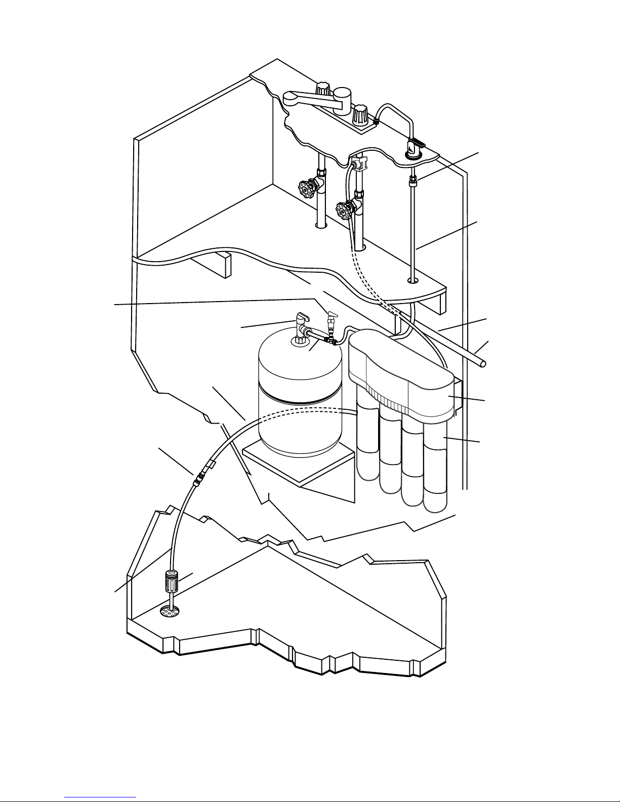
Fig. 7
(FLOOR)
Faucetwithout
AirGap
3/8”Blue
Tubing*
Forrefrigera-
tor icemaker or
water dispenser
hookup, tee into
tubing
FaucetAdapter
Cold Water
SupplyPipe
3/8”Yellow
Tubing*
Storage
Tank**
1/4”greentubing
AirGapDevice
(e.g.Gap-A-Flow)
LaundrySink,
Standpipe or
FloorDrain
(BasementFloor)
Storage Tank
Valve
RedSFCTubing
Filtration
assembly
*Forbestflow,keepthetubingasshortaspossible
**Mountthestoragetankonashelforstrapitbetweentwofloorjoists
1/4”Orange
Tubing
SQC3-has3cartridges
SQC 4 (shown)
ReducingUnion
PressureRelief
Valve(Required,
not Included)

11
O. APPENDIXFORBASEMENTINSTALLATIONS
The following variations are generally required for basement
installations:
INSTALL THE DRAIN CONNECTION
For basement installations, the drain saddle is generally
not used. Instead, the RO reject line (SFC tubing) is routed
so that it drains into a laundry sink, floor drain, or standpipe
through an approved air gap.
MOUNT THE FAUCET
If you choose to use the air gap faucet included with the
RO system, follow the faucet installation instructions given ear-
lier in this manual. Do not hook up any air gap tubing to the
faucet since an alternate air gap will be used elsewhere in the
drain line.
If you choose to use the optional non-air gap faucet, follow
the instructions below.
A) Familiarize yourself with all of the components shown in
the diagram of the non-air gap faucet. (See Fig. 2)
B) Install only the chrome base plate and rubber sealing washer
onto the threaded nipple. (Plumbers’ putty may be used in
place of the sealing washer for a neater appearance.)
C) Feed the threaded nipple through the sink/countertop
mounting hole (a 9/16” hole is adequate).
D) From underneath the sink/countertop, install the plastic
bottom washer, flat washer, star washer, and hex nut onto
the threaded nipple. Hand tighten the hex nut until the
faucet feels snug.
E) After rechecking the faucet orientation, tighten the hex nut
with at 9/16” wrench until the faucet feels secure.
F) From above the sink, make any minor orientation
corrections by turning the faucet on its “flats” with a
padded adjustable wrench. Use care so as not to mar the
chrome finish.
INSTALL THE FILTRATION ASSEMBLY AND THE
STORAGE TANK
The filtration assembly is generally mounted to the basement
wall (using wall anchors) or to the wood ceiling supports. To
mount the filtration assembly, keep the bracket level and mark the
location of the mounting holes. Install wall anchors and/or mount-
ing screws as required. Leave the screw heads protruding to
allow the bracket mounting slots to slide over them. (See Fig. 7)
The tank may be oriented either vertically or horizontally and
can be placed on a shelf, on the floor, or suspended from the ceil-
ing supports using brackets.
An effort should be made to minimize the distance between
the tank and filtration assembly in order to ensure an adequate
flow rate to the faucet.
MAKE THE TUBING CONNECTIONS
1) A proper length of the 1/4” orange feed water tubing
should already have been connected to the cold water
supply shut off valve. Route it through the large opening
in the bottom of the metal bracket and loop it back to the
“FEED” connection on the filtration assembly.
2) Connect a longer length of 3/8” blue tubing (not included) to
the faucet adapter. Route the tubing through the floor to the
location of the filtration assembly. Remove the existing
3/8” blue tubing from the filtration assembly. Route the
other end of the longer length of 3/8” blue tubing through the
large opening in the bottom of the metal bracket and connect
it to the “FAUCET” connection on the filtration assembly.
NOTE: Instead of removing the existing 3/8” blue tubing from
the filtration assembly, a 3/8” connector fitting can be used to
join the tubing from the faucet with the tubing from the filtration
assembly.
3) Route the 3/8” yellow tubing from the filtration assembly
to the storage tank.
4) Route 1/4” tubing from an appropriate drain connection
(e.g. laundry sink, floor drain, standpipe) to the location of
the filtration assembly. An air gap must be provided
between the outlet and the drain connection.
5) Connect the red SFC tubing from the filtration assembly
to the 14” tubing from the drain connection using the 1/4”
connector fitting on the end of the SFC tubing.

P. INSTALLATIONTROUBLESHOOTING
Problem: Leak at the drain saddle.
Possible Cause: Drain saddle not clamped tightly enough.
Solution: Tighten the drain saddle screws evenly and firmly.
Problem: Leak at the fittings threaded connection.
Possible Cause: Fitting is improperly taped or not `
tightened sufficiently.
Solution: Retape the threaded portion with PTFE tape and
thread it in firmly. Do not over tighten.
Problem: Leak at the fitting’s push-in connection.
Possible Cause: Tubing is damaged if there is a tubing mis-
assembly.
Solution: Remove the tubing. Squarely cut off 1/4 inch from
the end of the tubing using a sharp razor knife and reinsert it
into the fitting. Make sure that the tubing is pushed in com-
pletely until it seats.
Problem: Leak at the filter cartridge head.
Possible Cause: Damaged or misaligned O-ring.
Solution: Close the cold water supply shut off valve and the
storage tank valve. Lift up on the faucet handle and drain the
tank a minimum of 5 minutes. Remove the filter cartridge and
check the condition of the O-rings. If they are misaligned,
reseal them. If they are damaged, replace them.
Problem: The faucet leaks from the spout with the handle down.
Possible Cause: An obstructed or damaged valve seat in the
faucet mechanism.
Solution: Remove the faucet spout with a twisting/lifting
motion and slide the faucet handle forward over the spout
hole to gain access to the faucet valve. Unscrew the tee-bar
and the slotted bushing to remove the valve. Clean out any
obstruction or replace it with a new valve mechanism if neces-
sary.
Problem: No steady drip from the open faucet after the
tank is drained.
Possible Causes:
• The cold water supply shut off valve is not open.
• A leak from any product water fitting connection.
• The icemaker valve was left open before the start-up
procedure completed.
• Air is still trapped in the system.
Solutions:
• Open the cold water supply shut off valve completely.
• Correct the fitting leak as outlined above.
• Close the icemaker valve and wait until the faucet drips.
• Wait for the air to be purged from the system.
Problem: Water leaks from air gap module opening.
Possible Causes:
• The drain line tubing is looped, kinked, or has a low spot.
• The drain line is blocked or the drain hole is not drilled
through completely.
• Air is locked in the air gap outlet.
• There is excessive RO reject flow.
Solutions:
• Trim any excess tubing to obtain a short, “straight-shot” to
the drain.
• Check to see that the drain line is clear of any obstruction
and remove the drain saddle fitting to verify that the hole is
drilled through completely.
• Blow air into the air gap outlet using a short length of tubing.
• Disconnect the red SFC reject tubing from the faucet air
gap inlet tubing and check the reject flow rate. It should
be less than 5.9 ounces/min. If it is greater than 5.9 ounc
es/min, replace the red SFC reject tubing with the new one
of proper length.
Problem: Too little or no reject flow.
Possible Causes:
• Red SFC reject tubing is plugged or damaged.
• An obstruction in the faucet air gap module.
Solutions:
• Replace the SFC reject tubing with one of proper length.
• Remove the air gap module and inspect the internal flow
path. Replace the air gap module if necessary.
Problem: Chlorine or other unpleasant taste/odor is evi-
dent after the initial tank filling.
Possible Cause: Residual preservative/sanitizer is still in the
water.
Solution: Drain and fill the storage tank several times if
necessary.
Problem: Noise in the drain (gurgling or
dribbling sound).
Possible Cause: The reject water is dripping into the standing
water in the drain trap.
Solutions:
• Make sure that the 3/8” black drain tubing from the faucet
air gap module slopes continuously downward to the drain
saddle without any loops or low spots.
• Angle the drain piping so that the reject water runs down
the side of the drain pipe.
• Change the location of the drain saddle to the horizontal
drain pipe or any alternate vertical drain pipe which is
farther from the trap. Properly plug the original hole.
• Drill larger hole in drain pipe.
Caution: Make sure the drain saddle is always installed
above (before) the trap.
12

A. IMPORTANTWATERQUALITYASSURANCE
REQUIREMENTS
Reverse Osmosis drinking water appliances contain treat-
ment components that are critical for the effective reduction of
Total Dissolved Solids (TDS) as well as inorganic chemical con-
taminants. Water Factory Systems™strongly recommends that
the user test the water periodically (every six to twelve months
minimum) to verify that the appliance is performing satisfac-
torily. Your dealer may offer a water testing service. Routine
maintenance is necessary in the form of prefilter, postfilter, and
membrane replacement, based on the following guidelines:
• Sediment,Carbon,orSediment/CarbonPrefilters,and
Carbon Postfilters: Change every 12 months or sooner
depending on the feed water quality.
• RO Membrane: Change it as required based on Percent
Rejection. A testing service may be offered by your dealer
every 36 months or sooner.
B. REPLACINGTHEFILTERCARTRIDGES
The life of the prefilter cartridge generally depends on
the local water conditions (i.e., dirt, rust and/or chlorine
levels) while the life of the postfilter cartridge(s) is generally
determined by the length of service.
When to Replace the Sediment Replacement Filter
• Every twelve (12) months or sooner depending on local water
conditions.
• Anoticeabledecreaseinwaterproductionisanindication
that the filter requires changing.
When to Replace the Granulated Carbon Replacement
Filter
The granulated carbon replacement filter reduces free chlorine
in the feed water supply to protect the TFCM membrane from
chlorine attack. To find out the chlorine level in a water supply,
call the public water supplier.
When to Replace the Carbon Block Replacement
Post-Filter
• If the filter is being used to control tastes and odors, replace it
every twelve (12) months or sooner depending on local water
conditions.
When to Replace the Carbon Postfilter Cartridge
Change at a minimum of 12 months or sooner, depending
on feed water quality.
How to Replace the Prefilter and
Postfilter Cartridges
1) Lift up on the faucet handle to drain the tank. Close the
cold water supply valve. Wait five (5) minutes for the
filtration assembly to completely depressurize.
2) Remove cover and twist the filter cartridge 1/4 turn
clockwise so that the
ears on the cartridge are able to disengage from the
head. Firmly pull the cartridge from the head. It may
be necessary to twist the cartridge slightly from side to
side to help free it. (See Fig. 8)
3) Remove the new filter cartridge from its sanitary sealed
wrapper. (Double check to see that it is the correct
replacement by comparing the labels.)
4) Using tap water, wet the o-ring seals to make cartridge
insertion easier.
5) Line up the cartridge ears, insert the cartridge and push
it into the head until it is fully seated. Twist the
cartridge 1/4 turn counterclockwise to lock it into place.
6) Open the cold water supply valve and carefully check
for leaks.
7) RO System Flush Instructions:
Prefilter: Flush at least 2 gallons of water through filter
before use.
Postfilter: Flush at least 2 gallons of water through fil-
ter before use.
RO Membrane Cartridge: Run product water to drain for
24 hours.
C. REPLACINGTHEROMEMBRANECARTRIDGE
The life of the RO membrane cartridge depends on the
local water conditions and proper maintenance, e.g., regular
filter changes. The maximum recommended service life is
36 months. Unlike the filter cartridges, the RO membrane
cartridge life is not determined by the amount of water used
because of its self-cleaning feature.
II. Operation & Maintenance Instructions
13
To reduce the risk associated with property damage due to water leakage:
• Read and follow UseInstructionsbeforeinstallationanduseofthissystem.
• Installationanduse MUST comply with all state and local plumbing codes.
• Protect from freezing,removeltercartridgewhentemperaturesareexpectedtodropbelow40°F(4.4°C).
• Donotinstallifwaterpressureexceeds100psi(690kPa).Ifyourwaterpressureexceeds80psi(552kPa),youmust
install a pressure limiting valve. Contact a plumbing professional if you are uncertain how to check your water pressure.
• Donotinstallwherewaterhammerconditionsmayoccur.Ifwaterhammerconditionsexistyoumustinstalla
water hammer arrester. Contact a plumbing professional if you are uncertain how to check for this condition.
• ThedisposableltercartridgeMUST bereplacedevery12months,attheratedcapacityorsoonerifanoticeable
reductioninowrateoccurs.
• TheROMembranecartridgeMUST bereplacedatleastevery36months.

How to Replace the RO Membrane Cartridge
1) Close the cold water supply shut off valve. Lift up on the
faucet handle to drain the tank. Wait five (5) minutes for
the filtration assembly to completely depressurize.
2) Make sure that there is some slack in the red SFC tubing
connected to the fitting at the bottom of the RO membrane
cartridge. Twist the cartridge 1/4 turn clockwise so that
the tubing connection is accessible. (See Fig. 8)
3) Remove the red SFC tubing by depressing the small gray
collet and pulling the tubing away from the fitting.
Note: It is advisable to check the end of the red SFC tubing
for nicks or scratches. If any are observed, cut off 1/4” from
the end of the tubing with a sharp razor knife.
4) Firmly pull the cartridge away from the head. (It may be
necessary to twist the cartridge slightly from side to side.)
5) Remove the new RO membrane cartridge from its sanitary
sealed wrapper. (Double check to see that it is the correct
replacement by comparing the labels.) Rinse it with tap
water and dry it off.
6) Remove the white plug from the fitting at the bottom of the
cartridge by pushing in the small gray collet and pulling out
the plug.
7) Remove the red plastic cap from the top of the cartridge.
8) Using tap water, food grade silicone lubricant or glycerin,
wet the O-ring seals to make cartridge insertion easier.
9) Reconnect the red SFC reject tubing by inserting it into the
fitting at the bottom of the new RO membrane cartridge as far
as it will go. Line up the cartridge ears, insert the cartridge
and push it into the head until it is fully seated. Twist the
cartridge 1/4 turn counterclockwise to lock it into place.
10) Open
cold water supply valve
and carefully check for
leaks. Carefully inspect the fitting at the bottom of the new
RO membrane cartridge.
11) Follow the sanitizing procedure for the storage tank and
the filtration assembly outlined below.
D. YEARLYMAINTENANCESANITIZATION*
SANITIZINGTHEROAPPLIANCE
To assure the highest quality water from your RO Drinking
Water Appliance, it is important to routinely sanitize both the
storage tank and the filtration assembly.
IMPORTANT: These procedures are only intended to be
part of a routine maintenance program only and are not
designed to sanitize systems that have become highly
contaminated from misuse.
When to Sanitize the Storage Tank
• Upon start-up as described in the beginning of this manual.
• Afteranyservicingorroutinemaintenancethatinvolves
replacing the RO membrane cartridge, the postfilter(s), ser-
vicing the storage tank, or replacing the RO faucet.
When to Sanitize the Filtration Assembly
• Afteranyservicingorroutinemaintenancethatinvolves
replacing the RO membrane cartridge, the postfilter(s), ser-
vicing the storage tank, or replacing the RO faucet.
• Afteranyextendedperiodofnon-use(over30days)unless
the cartridges are stored inside a sealed plastic bag in the
refrigerator.
Remove the red SFC tubing from
the fitting before completely
removing the RO membrane modul
e
O
N
O
F
F
Fig. 8
14
* Initial sanitization to be performed using instructions on page 6.

How to Sanitize the Storage Tank and Filtration System
Sanitizing the storage tank generally requires:
• Common household bleach (5.25% non-scented)
• Eye dropper or plastic oral syringe
1) Close the cold water feed valve and lift up on the faucet
handle to empty the water in the storage tank. It should
feel light when empty.
2) Disconnect the 3/8” yellow tubing (system tank) from the
ball valve on top of the storage tank.
3) Insert into the yellow tubing 1/2 teaspoon (3 ml) of house-
hold bleach. (See Fig 9)
4) Reconnect the yellow tube to the tank ball valve.
5) Close the RO faucet and open the cold water feed valve.
6) Wait 4-5 hours.
7) Lift up the handle of the RO faucet and allow contents of
tank to drain completely into the sink.
8) Sanitizing is now complete.
9) If there is any residual chlorine/bleach taste in the next tank
full, drain tank completely a second time.
E. LONG TERM NON-USE
If the RO appliance is to be left unused for a long period of
time (greater than 30 days), follow this procedure:
1) Lift up on the faucet handle to drain the storage tank and
close the cold water supply shut off valve. Wait five min-
utes for the filtration assembly to depressurize.
2) Remove all of the filter cartridges. Turn the cartridges
upside down in the sink to drain out as much water from
them as possible.
3) Place the cartridges in an air tight plastic bag and store
them in the refrigerator.
IMPORTANT NOTE:
The cartridges must be not be allowed to freeze because
permanent damage may occur, which may result in property
damage due to water leakage.
4) When the RO appliance is ready to be put back into ser-
vice, reinstall the filter cartridges by matching the symbols
on the top of the cartridge labels with the ones on the
filtration assembly heads. Sanitize the storage tank as
described in the previous section. The filtration assembly
can be sanitized at this time if so desired.
5) Follow the start up procedure outlined in the previous
section.
15
Eyedropper
with Bleach
Prefilter
Cartridge
Cartridge Ear
1/2 Tsp.
5.25%
Unscented
Bleach
Eyedropper
with Bleach
Storage Tank
Fig. 9
To reduce the risk associated with ingestion of water contaminated with sanitizer:
• Sanitizermustbeushedfromthesystembeforeusingasdirectedwithintheinstallationinstructions.
To reduce the risk of injury associated with household bleach:
• Readandfollow manufacturers directions and cautions
• Keepoutofthereachofchildren
• DONOTintermixwithotherchemicals


3M Purification Inc.
400 Research Parkway
Meriden, CT 06450, U.S.A.
Tel (800) 733-1199
(203) 237-5541
Fax (203) 203-8701
www.3Mpurification.com
www.waterfactorysystems.com
Please recycle. Printed in U.S.A.
Water Factory System is a trademark of 3M Company used under license.
3M is a trademark of 3M Company.
© 2010 3M Company. All rights reserved.
98-880040 0210
Limited Warranty: 3MPuricationInc.warrantsthisProductwillbefreefromdefectsinmaterialandmanufactureforthefollowingperiodsfromthedateof
purchase:Ten(10)yearsfortheProduct,exceptforthereplacementltercartridgeandmembrane,whicharewarrantedforone(1)year.Thiswarrantydoes
notcoverfailuresresultingfromabuse,misuse,alterationordamagenotcausedby3Morfailuretofollowinstallationanduseinstructions.Nowarrantyis
givenastotheservicelifeofanyltercartridgeormembraneasitwillvarywithlocalwaterconditionsandwaterconsumption.IftheProductfailstosatisfy
thisLimitedWarrantyduringthewarrantyperiod,3MwillreplacetheProductorrefundyourProductpurchaseprice.Thiswarrantydoesnotcoverlabor.The
remedystatedinthisparagraphisCustomer’ssoleremedyand3M’sexclusiveobligation.
Thiswarrantygivesyouspeciclegalrights,andyoumayhaveotherrightswhichmayvaryfromstatetostate,orcountrytocountry.Foranywarranty
questions,pleasecall1-866-990-9785ormailyourrequestto:WarrantyClaims,3MPuricationInc.,400ResearchParkway,Meriden,CT06450.Proofof
purchase(originalsalesreceipt)mustaccompanythewarrantyclaim,alongwithacompletedescriptionoftheProduct,modelnumberandallegeddefect.
Limitation of Liability: 3M will not be liable for any loss or damage arising from this 3M product, whether direct, indirect, special, incidental, or consequen-
tial,regardlessofthelegaltheoryasserted,includingwarranty,contract,negligenceorstrictliability.Somestatesandcountriesdonotallowtheexclusionof
limitationofincidentalorconsequentialdamages,sotheabovelimitationorexclusionmaynotapplytoyou.
This manual suits for next models
1
Table of contents
Other Water Factory Systems Water Filtration System manuals


Popular Water Filtration System manuals by other brands


AquaMaster
AquaMaster AMS700 Owner's manual and installation guide

US Water Systems
US Water Systems Flexx Oxi-Gen FX-150 owner's manual

Pentair
Pentair Logix 762 user guide

Penguin Water
Penguin Water 200-PWRO Series manual

Pure-Pro
Pure-Pro WF-30 user manual

UV Dynamics
UV Dynamics UVD400 Installation and maintenance manual


