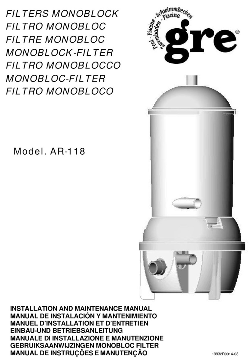
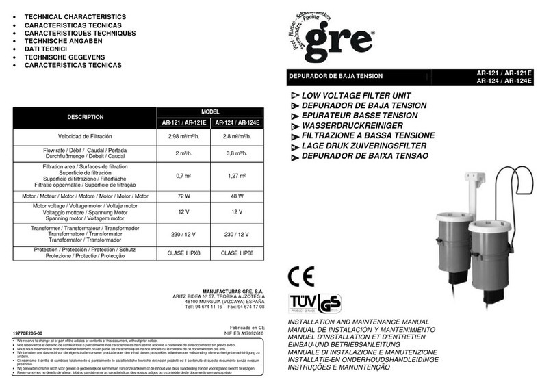
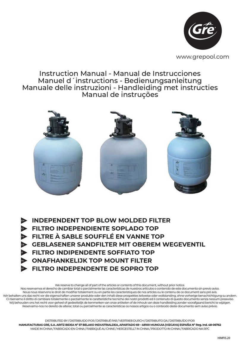
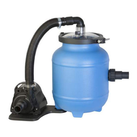
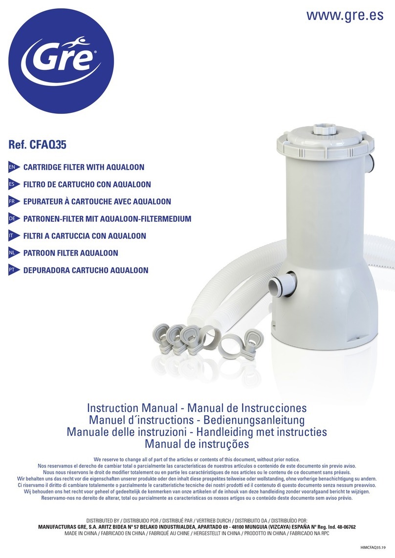
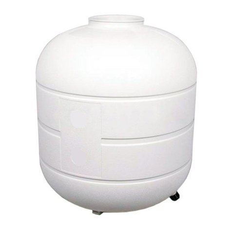
GRE FS550 Manual

INSTALLATION AND MAINTENANCE MANUAL
MANUAL DE INSTALACIÓN Y MANTENIMIENTO
MANUEL D´ INSTALLATION ET D´ENTRETIEN
EINBAU-UND BETRIEBSANLEITUNG
MANUALE DI INSTALLAZIONE E MANUTENZIONE
INSTALLATE EN ODERHOUD HANDLEIDING
MANUAL DE INSTRUÇÕES E MANUTENÇAÕ
MONOBLOCK FLITER ●FILTRO MONOBLOC ●FILTRE MONOBLOC ●MONOBLOCK-FILTER
FILTRO MONOBLOCCO ●MONOBLOCK FILTER ●FILTRO MONOBLOCO
HIMFILTROS.14
www.PiscineHorsSol.com

English - MONOBLOCK FILTER
INSTALLATION AND GENERAL MAINTENANCE MANUAL . . . . . . . . . . . . . . . . . .page 3
Español - FILTRO MONOBLOC
MANUAL DE INSTALACIÓN Y MANTENIMIENTO GENERAL . . . . . . . . . . . . . . .página 11
Français - FILTRE MONOBLOC
MANUEL D’INSTALLATION ET MAINTENANCE GÉNÉRAL . . . . . . . . . . . . . . . . . .page 19
Deutsch - MONOBLOCK-FILTER
EINBAU-UND BETRIEBSANLEITUNG . . . . . . . . . . . . . . . . . . . . . . . . . . . . . .Seite 27
Italiano - FILTRO MONOBLOCCO
MANUALE DI INSTALLAZIONE E MANUTENZIONE GENERALE . . . . . . . . . . . . .pagina 37
Nederland- MONOBLOCK FILTER
INSTALLATIE EN ODERHOUD HANDLEIDINGL . . . . . . . . . . . . . . . . . . . . . . . .page 45
Portugues -FILTRO MONOBLOCO
MANUAL DE INSTALAÇÃO E MANUTENÇÃO GERAL . . . . . . . . . . . . . . . . . . . .página 53
www.PiscineHorsSol.com

3
ENGLISH
Installation and General Maintenance Manual - POOL PUMPS
INSTRUCTIONS FILTRE MONOBLOC
Read manual carefully and keep it in a safe place for future reference.
This manual covers the filtration group which is described (name and reference) in the attached document "TECHNICAL
CARACTERISTICS".
• All electrical installations should comply with the following standard:
European Low Voltage Directive 2006/95/CE,
EN 60335-2-41, safety of household or similar electrical appliances, particular requirements for pumps.
As such with all rules pertaining to “to the construction of electrical installations within specific confines: swimming pools and
fountains”, or the equivalent standard in force in each region or country.
• The electrical installation should be done by someone qualified in working with electrical equipment. This equipment is not
designed for those with physical, sensory or mental handicap or people lacking in experience, unless done under supervision or
with instructions of use from a person in charge of safety.
• The height of the sand should not exceed 2/3 of the height of the tank.
• It is important to check that the suction ports are not blocked.
• Check regularly the filter level of dirtiness.
• The equipment must not be switched on while the pool is being used.
• Do not operate the equipment unless it is properly primed.
• NEVER touch the filter when it is operating if you are wet or have wet hands.
• When handling the filter or valve, DISCONNECT the power supply.
• Make sure that the ground is dry before touching the electrical equipment.
• Do not submerge the equipment or put it in a place where it could be submerged.
• Do not permit children nor adults to sit or lean on the equipment. Children should be supervised to ensure that they do not play
with the equipment.
• If the supply cord is damaged, it must be replaced by the manufacturer or its service agent or a similarly qualified person in order
to avoid a hazard.
• It is essential that any damaged element or set of elements is changed as soon as possible. Only use parts that are approved by
the sales representative.
• The equipment should be connected to a power supply (see data on the pump’s plate), with earth connection, protected by a
residual current device (RCD) having a rated residual operating current not exceeding 30 mA. or by an insulating transformer.
• Forbid access to the pool if any damage of the filtration system(s) occurs.
• Where chemical products are used to treat the pool water, it is recommended that a minimum filtration time is respected in order
to protect bathers' health, as stated by the health regulations.
FIG. POS. NAME
11A 4 functions valve
1 1B 5 functions valve
1 1C 6 functions valve
1 2 Filter
1 3 Monobloc base
1 4 Conection hose valve-pump
1 5 Pump
Some of the equipment's accessories (silica sand, hoses, manometers...) are not included in all models of monoblocs.
1 PACKING COMPONENTS
The equipment which you have just purchased is a special apparatus conceived and designed especially for above ground
swimming pools. As a result of its innovative design and high level of functionality, it provides you with the different components
required to filter water: filter, pump and selector valve in a single unit. The main components of this filter are as follows:
www.PiscineHorsSol.com

ENGLISH
MONOBLOCK FILTER - Installation and General Maintenance Manual4
REQUIREMENTS FOR CORRECT INSTALLATION
This filter is easy to install and can be assembled by one adult in about 2 hours, taking care to follow the instructions detailed
in this manual correctly. Only the following tools are required to correctly handle the filter components and to install it:
2 BEFORE CONNECTING THE FILTER
LOCATION
Place the filter on a flat, solid surface at a minimum distance of 3.5 meters from the pool (in accordance with standard installation
regulations of electric equipment in swimming pools in force in each region or country) and at the same level as the bottom of the
pool to prevent air from entering the cleansing circuit and to ensure that the filter remains primed (Fig. 2). The filter should be
protected from sun and rain, and kept in a sufficiently ventilated area during operation. Never cover it during operation.
In models where pool connection hoses are supplied, these will be 4.5 metres in length. In all cases, check that this length is
sufficient in order to install the apparatus on a flat, solid surface more than 3.5 metres away from the pool. If the hose length
is insufficient, contact your service centre.
When hoses are not supplied with the apparatus, hoses with a minimum length of 4.5 metres should be used which allow the
filtering equipment to be placed on a flat, solid surface more than 3.5 metres away from the pool. This hose set is available
as an optional kit from your vendor.
It is important to check that the suction ports are not blocked.
During the installation process, if in doubt, contact the vendor of the equipment
ASSEMBLY
Once the filter is set in place, proceed as follows:
• Fix the filter to the base. Depending on the monoblock filter.
• Fix the pump to the base with the screws and washers supplied (Fig. 10).
• Place the inner collector correctly on the bottom of the filter (Fig. 9).
• Cover the mouth of the collector situated on the inside of the filter with a plastic protector to make sure sand does not enter (Fig. 4).
• Put the sand inside the filter: The height of the sand should not exceed 2/3 of the height of the tank (Fig.4).
The silica sand lasts for an unlimited period of time. It should only be replaced if lost. Record the reference of the level of
silica sand for future replacement (Fig. 4).
• Remove the remains of sand from the filter opening and take off the protective plastic.
• Put the selector valve with its coupling and secure with the metal band or seal (Fig. 3).
• Firmly tighten the screw on the metal band which joins the valve to the filter (Fig. 3).
• Connect the (PUMP) and (RETURN) terminals of the selector valve to the corresponding hoses, tightening them firmly with
the clamps (Fig. 5).
NOTE: Check that the hoses allow the filtering equipment to be located and fixed on a flat, solid surface that is more than 3.5
metres from the pool.
TASK TOOL ALTERNATIVE TOOL
Tighten the hose flanges 7 mm Stecker screwdriver Philips screwdriver
Tighten the pump screws Open-end or socket wrench Open-end or socket wrench 13
Cut the liner Cutter knife
Protection of collector pipe Piece of plastic Piece of fabric
www.PiscineHorsSol.com

ENGLISH
Installation and General Maintenance Manual - MONOBLOCK FILTER 5
• Connect the other end of the suction hose to the skimmer tightening firmly with a clamp. Repeat the same procedure with
the return nozzle terminal and connect the discharge hose.
• Following installation, the first cycle of filter backwash should be performed. In order to do so, follow the instructions in section 5.3.
• It is important to check that the suction ports are not blocked.
3 ELECTRICAL CONNECTION
All electrical installations should comply with the following standard:
European Low Voltage Directive 2006/95/CE,
EN 60335-2-41, safety of household or similar electrical appliances, particular requirements for pumps.
As such with all rules pertaining to “to the construction of electrical installations within specific confines: swimming pools and
fountains”, or the equivalent standard in force in each region or country.
The equipment should be connected to a voltage (see data on the pump’s plate)power supply, with earth connection, protected
by a residual current device (RCD) having a rated residual operating current not exceeding 30 mA. (Not supplied; available for
purchase in electrical shops). or by an insulating transformer.
4 TOP SELECTOR VALVE
VALVE TYPES AND FUNCTIONING
A- 4 function valve: The top selector valve on the filter is used to select the 4 different filter functions: filtration (filter), backwash,
waste and closed.
B- 5 function valve: The top selector valve on the filter is used to select the 5 different filter functions: filter, backwash,rinse,
waste and closed.
C- 6 function valve: The top selector valve on the filter is used to select the 6 different filter functions: filter, backwash,
recirculate, rinse, waste and closed.
To vary the position of the 4 function valve, proceed as follows: (Fig. 6)
• Disconnect the equipment from the mains.
• Loosen the upper triangular knob on the valve by turning it until you can lift the cover of the housing and turn it.
• Turn the cover until the desired setting is aligned with the discharge hose, where the anchorage is, and the rib is
inserted in its housing.
• Re-tighten the knob by turning it, but be careful not to over-tighten so as not to damage the internal components of the valve.
To vary the position of the 5 function valve / 6 function valve, proceed as follows: (Fig. 7)
• Disconnect the equipment from the current.
• Firmly press the upper selector valve, displacing the front rib, until you can turn it.
• Turn the control gently until the front rib is in line with the desired operation.
• Slowly release the control, making sure that the front rib is sitting firmly in its place
ASSEMBLING THE PRESSURE GAUGE
WITHOUT PRESSURE GAUGE 1 2
www.PiscineHorsSol.com

ENGLISH
MONOBLOCK FILTER - Installation and General Maintenance Manual6
5 OPERATION
The operation of this filter is based on the filtration capacity of the silica sand which is inside. The water in the pool is driven by the
filter pump and forced to pass through the silica sand. The sand acts as a filtering element which retains the impurities in the water.
The environment, trees, pollen, insects and frequency of bathing, amongst other factors, determine the dirtiness of the water in
the pool. Depending on these factors, the silica sand in the filter should be cleaned with greater or less frequency (see section
5.3). Check regularly the filter level of dirtiness.
To keep the pool water in good condition, use the chemical products recommended by the manufacturer (chlorine, alga
protection, flocculants, etc.).
CHEMICAL PRODUCTS SHOULD NEVER BE PLACED IN THE BASKET OR THROUGH THE FILTER, AS THIS WOULD
DETERIORATE THE MATERIALS OF THE UNIT AND LIMIT ITS EFFICACY.
Where chemical products are used to treat the pool water, it is recommended that a minimum filtration time is respected in
order to protect bathers' health, as stated by the health regulations.
5.1 PRIMNG THE FILTER
The filter must be correctly primed at all times. If the filter is not primed it means that an air chamber has been created inside which
causes defective circulation of water. This prevents proper filtration of the water by the silica sand and is detrimental to the motor.
The filter may become unprimed for several reasons:
• Starting up a new unit.
• Starting up a unit after an extended period of inactivity.
• Following use of a suction bottom cleaner.
• Air absorbed by the skimmer due to the low level of water in the pool.
• Due to incorrect use of the unit, suction cover or skimmer plug.
When is the filter unprimed?
We can see that the filter is unprimed when:
• The water entering the filter sounds like it is falling freely. This indicates that an air chamber has been created between the
water inlet and the silica sand.
• An excess of air bubbles is released through the return nozzle.
• The bottom cleaner (not supplied) does not operate with suction, and the silica sand remains clean after cleaning.
How can we prime the filter?
• Verify that the suction hose is connected to the skimmer and the passage is clear (the plug is not in place).
• With the valve on the filter position, slightly loosen the drain nut which is beside the pressure gauge, so as the air
accumulated inside the filter can leave.
• When you see that only water is released (for 1 to 2 minutes), re-tighten the nut.
5.2 FILTRATION
NEVER HANDLE THE VALVE WHILE THE MOTOR IS RUNNING
Carry out a wash of the sand before the first filtration. (Part 5.3)
The valve should be in the filter position (FILTER). The service life of the filter will be longer if the periods of continuous operation do not exceed 4
hours.Theneedfordailyfiltrationisdeterminedbythevolumeofwaterinyourpoolinm3inrelationtothem3/hfilterflowrateforawatertemperature
of approximately 21ºC and placed 3.5 m from the pool. Leave the motor at a standstill for at least 2 h between each 4 h period of operation.
Pool volume in m3= Hours required Example: 42 m3=7.63 hours
Filter flow rate in m3/h 5.5 m3/h 2 cycles of 4 hours with a break of 2 hours
www.PiscineHorsSol.com

ENGLISH
Installation and General Maintenance Manual - MONOBLOCK FILTER 7
In the initial filtration treatment it is important to leave the filter at a standstill for the periods indicated. It is recommended
that you increase the amount of time in ratio to any temperature rise in the pool.
5.3 FILTER BACKWASH
The backwash process cleans the silica sand from inside the filter. This is achieved by reversing the direction of water circulation
with the top selector valve. This process should be done regularly. For this purpose you should observe several factors which
indicate the dirtiness of the sand:
•When a reduction in the return flow rate of over 30% of the system's nominal flow rate is detected.
•When the manometer indicates an excessive pressure (see the maximum working pressure given in the instruction manual
included with the device).
To clean the filter, proceed as follows according to valve type:
4 function valve: (Fig. 6)
•Disconnect the filter from the mains. Never move the selector valve while the motor is running.
•Loosen the upper triangular knob on the valve until you can lift the cover and turn it (Fig.6). Place the valve on the backwash
setting, reinserting the cover in its housing and re-tightening the knob by turning it. Do not over-tighten the knob so as to
avoid damaging the valve.
•Connect a hose to the valve waste outlet from the valve and direct the other end of the hose to a drain or sewer.
•Run the filter for approximately 2 minutes (until impurities no longer run out with the water).
•Stop the filter and leave it to rest for 2 minutes so as to let the silica settle and stop it from running out into the pool.
•Reset the valve to the desired setting (filtration or closed) (Fig. 6) and remove the hose from the drain outlet.
For 5 and 6 function valves: (Fig. 7 and Fig.8)
•Disconnect the filter from the mains. Never move the selector valve while the motor is running.
•Firmly press the upper selector valve, displacing the front rib, until you can turn it (Fig. 7).
• Turn the control gently until the front rib is in line with the backwash operation (Fig. 7).
•Connect a hose to the valve waste outlet from the valve and direct the other end of the hose to a drain or sewer.
•Run the filter for approximately 2 minutes (until impurities no longer run out with the water). In the valve model fig.8, this
can be seen through the transparent window on the side.
•Stop the equipment.
• Put the valve in the rinse position and connect the filter for a few seconds (Fig. 7).
•Stop the equipment, put it in the desired filter position (Fig. 7) and remove the hose from the waste position, if you desire.
5.4 DRAINING THE POOL
The filter allows you to drain nearly the entire poolafter the bathing season has ended. In order to do so, you should set the
top selector valve on the waste setting (Fig. 6) (Fig. 7) without plugging in the filter and connect a hose to the valve waste
outlet and direct the other end to the drain or sewer.
Depending on the skimmer model (see specific manual), proceed as follows:
5.4.1 With wall skimmer (for Dream Pool swimming pools):
•Remove the inner basket from the skimmer and cover the suction inlet with the plug supplied for this purpose.
•Disconnect the suction hose from the skimmer inlet. Loosen the clamp which secures the hose, supporting it so that no water
leaks and it loses priming.
•Remove the hose, covering the end so it remains primed, and submerge it immediately in the pool.
•Weigh down the end of the suction hose with a heavy object which will not damage the liner so that it is forced to sink to
the bottom of the pool.
•Start up the pump and drain the pool. Remember that the filter will not fully drain the pool. When a few centimetres of
water are left and the pump no longer sucks in water, turn it off.
www.PiscineHorsSol.com

ENGLISH
MONOBLOCK FILTER - Installation and General Maintenance Manual
8
• If you are going to refill the pool with water, first manually remove the remaining water without damaging the liner.
• If you are going to disassemble the pool, you can fold the bag with the remaining water in the centre and after removing
the plate, unfold the bag to empty it completely. This operation should only be done when you are disassembling the pool.
5.4.2. With self-supporting skimmer (for Magic Pool swimming pools):
Aside from the drain included within the pool, you can use the filter system to empty it:
• Raise the self-supporting skimmer until it is hanging outside the pool, to prevent water from entering the skimmer.
• Disconnect the suction hose from the skimmer inlet by the outer part of the pool wall. Loosen the clamp which secures the
hose carefully so that the liner is not damaged. Hold the hose so that no water leaks and it loses priming.
• Remove the hose, covering the end so it remains primed, and submerge it immediately in the pool.
• Weigh down the end of the suction hose of the skimmer inlet with a heavy object which will not damage the liner so that it
is forced to sink to the bottom of the pool.
• Start up the pump and drain the pool. Remember that the filter will not fully drain the pool. When the pump no longer sucks
in water, turn it off.
• If you are going to refill the pool with water, first remove the remaining water through the drain without damaging the pool.
THE HOSE SHOULD NOT CONTINUE TO APPLY SUCTION TO THE BOTTOM OF THE POOL LINER. THE PUMP MAY
BE SERIOUSLY DAMAGED IF IT OPERATES WITHOUT WATER CIRCULATION OR MAY DAMAGE THE LINER.
5.5 CLEANING THE BOTTOM OF THE POOL
To clean the bottom of the pool, you can use the unit's pump, using one of the following accessories:
• AR20637 or 08011 (a 32 mm diameter hose will be needed) for units FA6030 and FA6040.
• AR2064 (a 38 mm diameter hose will be needed) for units FA6050, FA6070, FA6080 and FA6100.
For any enquiries on warranties or after-sales service, please contact the vendor.
A hose which extends beyond the length required to reach all points of the pool is more difficult to use. Cut off the section of
the hose which is not needed. Check that the rubber terminals conserve their seal.
Priming the bottom cleaner hose:
Insert the bottom cleaner into the pool vertically, with the pole and the hose connected. Let it fill with water and keep the rest
of the hose outside of the water. Continue to insert the hose in the water slowly by 50 cm sections which should be submerged
at the same time as they are completely filled with water. Proceed up until the end, when the entire hose is filled with water
and submerged. If the hose is not fully primed, the bottom cleaner will not perform suction and the cleansing unit may be
damaged if it is forced to operate when it is empty.
Depending on the skimmer model (see specific manual), proceed as follows:
5.5.1. With wall skimmer (Dream Pool swimming pools):
• Place the suction cover accessory inside the skimmer with the inlet facing upwards, without removing the basket.
• Prime the hose.
• Pass the end of the hose through the gate of the skimmer from the INSIDE OF THE POOL, ensuring that no air gets in. Connect
it to the inlet of the suction cover, pressing it at a slant to create the join. Then insert it horizontally, introducing the hose
further. Pay attention not to damage the skimmer gate during this operation.
• The water level of the skimmer should be at a maximum and above the join between the cover and the hose to prevent air
from entering.
• Run the pump in the FILTER position and clean the bottom of the pool.
5.5.2. With self-supporting skimmer (Magic Pool swimming pools):
• Remove the upper floating ring from the skimmer and without removing the preliminary filtration basket, place the suction
cover accessory in the upper part of the skimmer with the inlet facing upwards and immerse the skimmer inside the pool
sufficiently to ensure that the suction cover does not take in air.
www.PiscineHorsSol.com
FS300,FS300NP,FS400, FS400T and FS500
FS250 and FS250NP

ENGLISH
Installation and General Maintenance Manual - MONOBLOCK FILTER 9
• Prime the hose.
• Ensuring that no air enters, connect the hose to the suction cover inlet. The join between the hose and the cover should always
be submerged to prevent air from entering.
• Run the pump and clean the bottom of the pool.
5.6 RINSING MODELS 5 FUNCTION VALVE / 6 FUNCTION VALVE: (FIG. 7)
Having completed a “WASH” cycle of the filter and having put the installation on “FILTER”, for a few seconds the water will
be cloudy flowing into the pool. To avoid having this cloudy water running into the pool, you can use the “RINSE” setting.
This works as follows: immediately after the “WASH”, stop the pump, turn the valve to “RINSE” (fig. 7) and connect the pump
again for one minute, then stop the pump and turn the valve to “FILTER”.
5.7 RECIRCULATION: MODEL 6 FUNCTION VALVE
With the valve in this position, the water goes directly from the pump to the pool, without passing through the filter (Fig. 7).
5.8 CLOSED SETTING
The “CLOSED” setting for the selector valve is used to prevent water from circulating through the hoses and the filter.
6 CABLE REPLACEMENT
If the supply cord is damaged, it must be replaced by the manufacturer or its service agent or a similarly qualified person in
order to avoid a hazard.
7 MAINTENANCE
After the bathing season has ended, the filter should be kept in a dry place where it is protected from bad weather. For this
reason, after performing a final backwash to clean the silica sand, dismantle the hoses and drain the water in the filter through
the tank drain plug until it is completely empty.
After removing all of the water from the filter, carefully clean the remains of silica sand from the thread before replacing the
plug. Failure to do so could damage the thread.
The filter tank drain plug should only be used in this operation.
VERY IMPORTANT:
Following an extended period of inactivity, before starting up the filter check that the filter is correctly primed.
7.1 CARE OF THE PUMP
The filter pump is designed to operate without any specific maintenance. Some consumable elements or those that are exposed
to wear and tear may have a shorter life-span than the guarantee period.
For any form of maintenance, contact the manufacturer or its service centre.
TROUBLE-SHOOTING AND TECHNICAL ASSISTANCE
This filter and its instructions are especially designed for home use. There is no need for professional assistance, except in special
cases. The following are some of the problems and causes which may arise over time during the life-span of the filter, and which you
may be able to fix on your own. For any enquiries on warranties or after-sales service, please contact the vendor.
It is essential that any damaged element or set of elements is changed as soon as possible. Only use parts that are approved
by the sales representative.
www.PiscineHorsSol.com

ENGLISH
MONOBLOCK FILTER - Installation and General Maintenance Manual10
Forbid access to the pool if any damage of the filtration system(s) occurs.
When handling the filter or valve, DISCONNECT the power supply.
PROBLEM CAUSE SOLUTION
Water leakage. Analyze the reason for water loss.
Ensure that the clamps and terminals are in the
correct position and have been tightened.
If the water loss continues contact the pool
manufacturer’s after-sales service.
After the filter has started up, there
is no flow in the return nozzle.
The valve is not in the “filter” setting.
The filter is above the level of the water
and is unprimed.
The suction cover or the skimmer plug has
been inserted.
Disconnect the filter and put the valve in the
correct setting.
Place the filter in the correct position and prime it.
Remove the suction cover or the skimmer plug.
Intermittent operation. Low water level on skimmer.
The filter is not primed.
Fill the pool and prime the filter.
Prime the filter.
The flow rate of the filter is low. Due to use, the filter is dirty.
The filter is not primed.
Perform a backwash.
Prime the filter.
Water comes out through the
mouth of the filter.
The connection between the valve and the
filter is dirty.
The metal band is loose.
Clean the sand from the opening. Insert the
coupling on the valve properly and tighten the
metal band firmly.
The filter valve leaks through the
drain terminal (WASTE).
Damage of inner coupling due to incorrect
use of chemical products.
Valve head broken due to incorrect use
(over-tightening).
Change the top valve cover.
Do not put chemical products in the preliminary
filtration skimmer basket.
Change the valve head; do not over-tighten.
The motor does not start up.
It makes no noise or vibration. There is no current in the electrical line. Make sure that there is current running in the
electrical line.
The motor does not start but a
buzzing sound can be heard. Problem with the motor. Please contact the vendor.
www.PiscineHorsSol.com

Manual de instalación y mantenimiento - FILTRO MONOBLOC 11
ESPAÑOL
1 COMPONENTES EMBALAJE
El equipo que acaba usted de comprar es un aparato especialmente concebido y diseñado para piscinas elevadas. Con un
innovador diseño y una gran funcionalidad, dispone usted de los diferentes elementos necesarios para filtrar el agua: Filtro,
bomba y válvula selectora en un mismo aparato. Los principales componentes de este equipo son:
INSTRUCCIONES FILTRO MONOBLOC
Lea atentamente y guarde esta documentación para futuras consultas.
Este manual cubre el grupo de filtración que se describe (nombre y referencia) en el documento adjunto "CARACTERÍSTICAS TÉCNICAS "
• En todo lo referente a la instalación eléctrica debe seguirse la normativa:
Directiva Europea 2006/95/CE de aparatos de baja tensión,
EN 60335-2-41, seguridad en aparatos electrodomésticos y análogos, requisitos particulares para bombas
Así cómo toda la normativa aplicable que haga referencia “a la construcción de instalaciones eléctricas en confines especiales. Piscinas
y fuentes”, o análogas, vigente en cada zona o país.
• La instalación eléctrica debe ser hecha por personal profesional cualificado en instalaciones eléctricas. Éste equipo no está destinado
a personas con capacidades físicas, sensoriales o mentales reducidas o sin experiencia, a no ser que hayan tenido supervisión o
instrucciones acerca de su uso por un responsable de seguridad.
• La altura de la arena no debe sobrepasar los 2/3 de la altura del depósito.
• Es obligatorio verificar que los orificios de aspiración no estén obturados.
• Se debe comprobar regularmente el nivel de obturación del filtro.
• No tenga el aparato en marcha mientras utiliza la piscina.
• No haga funcionar el equipo sin estar correctamente cebado.
• No toque NUNCA el equipo en marcha con el cuerpo húmedo o las manos húmedas.
• Siempre que deba manipular el equipo o la válvula, DESCONÉCTELO de la tóma de corriente.
• Asegúrese de que el suelo está seco antes de tocar el equipo eléctrico.
• No coloque el equipo sumergido o donde pueda quedar sumergido.
• No permita ni a niños ni a adultos apoyarse o sentarse sobre el equipo. Los niños deben ser supervisados para asegurar que no juegan
con el equipo.
• Si el cable de alimentación está dañado, debe ser substituído por el fabricante, por su servicio postventa o por personal cualificado
similar con el fin de evitar un peligro.
• Es obligatorio cambiar lo antes posible el elemento o el conjunto de elementos deteriorados. Sólo deben utilizarse piezas aprobadas
por el responsable de comercialización.
• El equipo se debe conectar a una toma de corriente (ver chapa característica bomba), con conexión a tierra, protegida con un
interruptor diferencial (RCD) con una corriente de funcionamiento residual asignada que no exceda de 30 mA, o a través de un
transformador de aislamiento..
• Se debe prohibir el acceso a la piscina en caso de deterioro del sistema o los sistemas de filtración.
• Cuando se utilicen productos químicos para tratar el agua de la piscina, se recomienda respetar un tiempo mínimo de filtración a fin
de preservar la salud de los bañistas que depende del cumplimiento de las normas sanitarias.
FIG. POS. NAME
11A Válvula 4 funciones
1 1B Válvula 5 funciones
1 1C Válvula 6 funciones
1 2 Filtro
1 3 Base monobloc
1 4 Manguera conexión válvula-bomba
1 5 Bomba
Existen algunos accesorios del equipo (Arena sílex, mangueras, manómetros...) que no están incluidos en todos los modelos de monoblocs.
www.PiscineHorsSol.com

NECESIDADES PARA UNA CORRECTA INSTALACIÓN
Por su facilidad de instalación este equipo puede ser montado por una persona adulta y en un periodo de tiempo de alrededor de
2 horas, con la precaución en todo momento de hacer un correcto seguimiento de las instrucciones detalladas en este manual. Para
una manipulación correcta de los componentes del equipo y su correcta instalación son necesarias las siguientes herramientas:
2 ANTES DE CONECTAR EL FILTRO
SITUACIÓN
Colocar el equipo sobre una superficie plana y sólida, a una distancia no inferior a 3,5 metros de la piscina (según norma de
instalación de equipos eléctricos en piscinas vigente en cada zona o país.) y al mismo nivel del fondo de la piscina para evitar que
entre aire en el circuito de depuración y el filtro se descebe (Fig. 2). Es conveniente resguardar el equipo del sol y la lluvia, y
mantenerlo con una ventilación suficiente durante su funcionamiento. Nunca tapar el equipo durante su funcionamiento.
En los equipos en los que se proporcionan las mangueras de conexión con la piscina, éstas tienen una longitud de 4,5 metros.
Comprobar, en todos los casos, que dicha longitud sea suficiente para la colocación del equipo en una superficie plana ysólida y situado
a más de 3,5 metros de la piscina. En el caso que la longitud de las mangueras no fuera suficiente, contacte con su servicio técnico.
En el caso que no se proporcionen las mangueras con el equipo, se deberán usar unas mangueras de longitud mínima de 4,5 metros
que permitan la situación del equipo de filtrado en una superficie plana y sólida y a más de 3,5 metros de la piscina. Dicho juego
de mangueras existe cómo kit opcional en su vendedor.
Es obligatorio verificar que los orificios de aspiración no estén obturados.
Durante el proceso de instalación, en caso de duda contacte con el vendedor del equipo.
MONTAJE
Una vez situado el equipo, proceder como sigue:
•Fijar filtro a base monobloc según modelo.
•Fijar la bomba en la base monobloc con los tornillos y arandelas subministradas, (Fig.10).
•Asentar correctamente el colector interior en el fondo del filtro, (Fig.9).
• Tapar la boca del colector situado en el interior del filtro con un plástico protector para evitar la entrada de arena (Fig.4).
•Introducir la arena en el interior del filtro: La altura de la arena no debe sobrepasar los 2/3 de la altura del depósito (Fig.4).
La arena de sílex tiene una duración ilimitada. Sólo debe reponerse en caso de pérdida. Tome la referencia del nivel de arena
de sílex para reposiciones futuras, (Fig.4).
•Eliminar los restos de arena de la boca del filtro y retirar el plástico protector.
•Colocar la válvula selectora con su junta y colocar el zuncho o cierre, (Fig.3).
•Apretar fuertemente el tornillo del zuncho que sujeta la válvula al filtro, (Fig.3).
• Proceda a conectar en los terminales de (PUMP) y (RETURN) de la válvula selectora con las mangueras correspondientes,
fijándolas fuertemente con las abrazaderas. (Fig.5) .
NOTA: Comprobar que las mangueras permitan la situación y fijación del equipo de filtrado en una superficie plana y sólida y
a más de 3,5 metros de la piscina.
• Proceda a conectar el otro extremo de la manguera de aspiración al skimmer apretando fuertemente con una abrazadera,
repita la operación con el terminal de la boquilla de retorno y conecte la manguera de impulsión.
FILTR0 MONOBLOC - Manual de instalación y mantenimiento12
ESPAÑOL
FUNCIÓN HERRAMIENTA HERRAMIENTA ALTERNATIVA
Apretar las bridas de las manguerasDestornillador stecker 7mmDestornillador boca Philips
Apretar los tornillos de la bomba Llave de boca o tubo 13 Llave de boca o tubo 13
Recortar el liner Cutter Cuchilla
Protección del tubo del colector Trozo de plástico Trozo de tela
www.PiscineHorsSol.com

Manual de instalación y mantenimiento - FILTRO MONOBLOC 13
ESPAÑOL
• Una vez instalado, deberemos efectuar un primer ciclo de lavado del filtro, para ello seguiremos lo descrito en el apartado 5.3.
• Es obligatorio verificar que los orificios de aspiración no estén obturados.
3 CONEXIÓN ELÉCTRICA
En todo lo referente a la instalación eléctrica debe seguirse la normativa:
Directiva Europea 2006/95/CE de aparatos de baja tensión
EN 60335-2-41, seguridad en aparatos electrodomésticos y análogos, requisitos particulares para bombas.
Así cómo toda la normativa aplicable que haga referencia “a la construcción de instalaciones eléctricas en confines especiales.
Piscinas y fuentes”, o análogas, vigente en cada zona o país.
El equipo se debe conectar a una toma de tensión (véase los datos en la chapa característica de la bomba) con conexión a
tierra, protegida con un interruptor diferencial (RCD) con una corriente de funcionamiento residual asignada que no exceda de
30 mA. (No suministrado. Puede adquirirse en establecimientos de electricidad). o a través de un transformador de
aislamiento.
4 VÁLVULA SELECTORA SUPERIOR
TIPOS DE VALVULAS
A- Válvula 4 funciones: La válvula selectora superior del filtro es la encargada de seleccionar las 4 diferentes funciones del filtro:
filtración (filter), lavado (backwash), vaciado (waste) y cerrado (closed).
B- Válvula 5 funciones: La válvula selectora superior del filtro es la encargada de seleccionar las 5 diferentes funciones del filtro:
filtración (filter), lavado (backwash), enjuague (rinse), vaciado (waste) y cerrado (closed).
C- Válvula 6 funciones: La válvula selectora superior del filtro es la encargada de seleccionar las 6 diferentes funciones del filtro:
filtración (filter), lavado (backwash), recirculación (recirculate), enjuague (rinse), vaciado (waste) y cerrado (closed).
Para variar la posición de la válvula 4 funciones proceder como sigue: (Fig. 6)
• Desconectar el equipo de la toma de corriente.
• Aflojar el pomo triangular superior de la válvula hasta que nos permita levantar la tapa de su alojamiento y girarla.
• Girar la tapa hasta que la operación deseada esté alineada con la manguera de impulsión y el nervio quede encajado en
su alojamiento.
• Apretar el pomo de nuevo, no excesivamente ya que se pueden dañar elementos internos de la válvula.
Para variar la posición de la válvula 5 y 6 funciones proceder como sigue: (Fig.7)
• Desconectar el equipo de la toma de corriente.
• Presionar firmemente el mando superior de la válvula desencajando el nervio delantero de su alojamiento, hasta que nos
permita girar sobre sí mismo.
• Girar suavemente el mando hasta alinear el nervio delantero con el alojamiento de la operación deseada.
• Soltar el mando sin brusquedad, comprobando que el nervio delantero queda bien encajado en su alojamiento.
MONTAJE DEL MANÓMETRO EN MODELOS
SIN MANÓMETRO 1 2
www.PiscineHorsSol.com

FILTR0 MONOBLOC - Manual de instalación y mantenimiento14
ESPAÑOL
5 FUNCIONAMIENTO
El funcionamiento de este equipo se basa en la capacidad de filtrado de la arena de sílex que hay en su interior. El agua de la piscina
es impulsada por la bomba del filtro y forzada a pasar a través de la arena de sílex, quedando retenidas las impurezas del agua en
la arena que actúa de elemento filtrante. El ambiente, árboles, polen, insectos y frecuencia de baños, son entre otros, los factores
que determinan la suciedad del agua de la piscina. La arena de sílex del filtro se deberá limpiar con mayor o menor frecuencia en
función de dichos factores (ver apartado 5.3). Se debe comprobar regularmente el nivel de obturación del filtro.
Para mantener en buen estado el agua de la piscina debemos además utilizar los productos químicos aconsejados por el
fabricante (cloro, antialgas, floculante, etc.).
EN NINGÚN CASO EL PRODUCTO QUÍMICO DEBE PONERSE EN EL CESTO O A TRAVÉS DEL FILTRO, ELLO
DETERIORARÍA LOS MATERIALES DEL APARATO Y LIMITARÍA SU EFICACIA.
Cuando se utilicen productos químicos para tratar el agua de la piscina, se recomienda respetar un tiempo mínimo de filtración
a fin de preservar la salud de los bañistas que depende del cumplimiento de las normas sanitarias.
5.1 CEBADO DEL FILTRO
Es imprescindible que el filtro se encuentre en todo momento correctamente cebado. Que el filtro no este cebado significa que
en su interior se ha creado una cámara de aire que provoca una circulación defectuosa del agua, hecho este que impide el
correcto filtraje de la misma por parte de la arena de sílex y perjudica el motor.
El filtro puede descebarse por varios motivos:
• Puesta en marcha de un equipo nuevo.
• Puesta en marcha de un equipo tras un periodo largo de falta de utilización.
• Tras utilizar un limpiafondos de aspiración.
• Absorción de aire por el skimmer debido a un nivel bajo en el agua de la piscina.
• Por una incorrecta utilización del equipo, tapa de aspiración o tapón de skimmer.
¿Cuándo está descebado el filtro?
Detectaremos que el filtro está descebado cuando:
• Comprobemos que el sonido del agua entrando en él suena a caída libre, hecho que nos indica que entre la entrada del
agua y la arena de sílex se ha creado una cámara de aire.
• Comprobemos que por la boquilla de retorno salen burbujas de aire en exceso.
• Comprobemos que el limpiafondos (no suministrado) no aspira, teniendo límpia la arena de sílex tras un lavado.
¿Cómo cebar el filtro?
• Comprobar que la manguera de aspiración está conectada al skimmer y el paso abierto (no tiene el tapón puesto).
• Con la válvula en posición de filtrado (filter), aflojar ligeramente el tapón de purga que se encuentra junto al manómetro
para que permita salir el aire acumulado en el interior del filtro.
• Cuando se observe que solo sale agua (entre 1 y 2 minutos), cerrar de nuevo la tapón de purga.
5.2 FILTRACIÓN
NO MANIPULAR EN NINGÚN CASO LA VÁLVULA CON EL MOTOR EN MARCHA.
Previo a la filtración inicial realizar un lavado de la arena. (Apartado 5.3)
La válvula debe estar en posición de filtrado (FILTER). La vida útil del filtro se alarga con periodos de funcionamiento continuado
no superiores a 4 h. Sus necesidades de filtración diarias vienen determinadas por el volumen en m3de agua de su piscina en
relación a los m3/h de caudal del filtro para una temperatura del agua de 21ºC aproximadamente y colocado a 3,5 m de su
piscina. Deje al menos 2 h. de reposo al motor entre cada periodo de funcionamiento de 4 h.
www.PiscineHorsSol.com

Manual de instalación y mantenimiento - FILTRO MONOBLOC 15
ESPAÑOL
Volumen piscina en m3= Horas necesariasEjemplo:42 m3=7,63 horas
Caudal filtro en m3/h 5,5 m3/h 2 ciclos de 4 horas con un ciclo intermedio de 2 horas de descanso
En el tratamiento inicial de filtración debe respetar los periodos de reposo indicados. Se recomienda aumentar el tiempo de
filtración cuanto mayor sea la temperatura del agua de su piscina.
5.3 LAVADO DEL FILTRO
Con el proceso de autolavado procedemos a limpiar la arena de sílex del interior del filtro, para ello se invierte el sentido de
circulación del agua mediante la válvula selectora superior. Este proceso debe hacerse con regularidad, para ello se debe estar
atento a varios factores que determinan que la arena está sucia:
•Que se detecte una disminución del caudal de retorno de más del 30% del caudal nominal del equipo.
•Que el manómetro nos indique una presión excesiva (ver presión máxima de trabajo indicada en la documentación del equipo).
Para el lavado de la arena deberemos proceder como sigue:
Válvula 4 funciones: (Fig. 6)
•Desconectar el equipo de la toma de corriente. No mover nunca la válvula selectora con el motor en marcha
• Aflojar el pomo triangular superior de la válvula hasta que nos permita levantar la tapa de su alojamiento y girarla (Fig.
6). Poner la válvula en posición de autolavado (backwash), encajando nuevamente la tapa en su alojamiento y volver a
apretar el pomo, no excesivamente, podría deteriorarse la válvula.
•Conectar una manguera a la salida de desagüe (waste) de la válvula y dirigir el otro extremo de la manguera a un desagüe
o alcantarilla.
• Poner en marcha el filtro durante 2 min. aproximadamente (hasta que dejen de salir impurezas con el agua).
• Parar el filtro y dejar reposar durante 2 min. para permitir el asentamiento del sílex y evitar su expulsión a la piscina.
• Volver a colocar la válvula en posición deseada (filtrado o cerrado) (Fig. 6) y retirar la manguera de la salida de desagüe
Válvula 5 y 6 funciones: (Fig. 7 y 8)
•Desconectar el equipo de la toma de corriente. No mover nunca la válvula selectora con el motor en marcha
• Presionar firmemente el mando superior de la válvula desencajando el nervio delantero de su alojamiento que nos permite
girar sobre sí mismo (Fig. 7).
•Girar suavemente el mando hasta alinear el nervio delantero con el alojamiento de la operación de lavado (backwash) (Fig. 7).
• Conectar una manguera a la salida de desagüe (waste) de la válvula y dirigir el otro extremo de la manguera a un desagüe
o alcantarilla.
• Poner en marcha el filtro durante 2 min. aproximadamente, hasta que dejen de salir impurezas con el agua. En el modelo
de válvula fig. 8 se puede observar a través de la mirilla transparente que hay en el lateral.
• Parar el equipo.
•Colocar la válvula en posición de enjuague (rinse) y conectar el filtro durante unos segundos (Fig. 7).
• Parar el equipo, pasar a la posición deseada de filtrado (filter) (Fig. 7) y retirar la manguera de la posición de desagüe
(waste), si se desea .
5.4 VACIADO DE LA PISCINA
El equipo le permite vaciar casi totalmentela piscina una vez terminada la temporada de baño. Para ello deberá poner
la válvula selectora superior en posición de desagüe (waste) (Fig. 6, Fig. 7), sin enchufar el equipo todavía, conectar una
manguera a la salida de desagüe (waste) de la válvula y dirigir el otro extremo de la manguera a un desagüe o alcantarilla.
Según el modelo de skimer (ver manual especifico), proceder como sigue:
5.4.1. Con skimmer de pared (Piscinas Dream Pool):
•Retirar el cesto interior del skimmer y tapar la aspiración con el tapón suministrado a tal efecto.
www.PiscineHorsSol.com

FILTR0 MONOBLOC - Manual de instalación y mantenimiento16
ESPAÑOL
• Desconectar la manguera de aspiración de la toma del skimmer, aflojando la abrazadera que la sujeta y sujetando la
manguera para que no pierda el agua y se descebe.
• Retirar la manguera, tapando el extremo para que no se descebe, y sumergirla inmediatamente en la piscina.
• Lastrar el extremo de la manguera de aspiración con un objeto pesado que no pueda dañar el liner, para forzar su inmersión
hasta el fondo de la piscina.
• Poner en marcha la bomba y proceder al vaciado de la piscina. Recuerde que con la ayuda del equipo no se vaciará
totalmente la piscina, cuando queden algunos cms de agua y la bomba ya no aspire agua deberá apagarla.
• Si va a llenar nuevamente la piscina de agua, antes saque manualmente el agua restante sin dañar el liner.
• Si va a desmontar la piscina puede plegar la bolsa con el agua restante en el centro y tras retirar la chapa,
desplegar la bolsa para vaciarla completamente. No se debe efectuar esta operación salvo para desmontar la piscina.
5.4.2. Con skimmer autoportante (Piscinas Magic Pool):
Además del desagüe que incorpora la piscina, puede utilizar la depuradora para vaciarla:
• Levantar el skimmer autoportante hasta que quede colgando por el lateral exterior de la piscina, para evitar que el agua entre en él.
• Desconectar la manguera de aspiración de la toma del skimmer por la parte exterior de la pared de la piscina, aflojando la
abrazadera que la sujeta con precaución para no dañar el liner y sujetando la manguera para que no pierda el agua y se descebe.
• Retirar la manguera, tapando el extremo para que no se descebe, y sumergirla inmediatamente en la piscina.
• Lastrar el extremo de la manguera de aspiración de la toma del skimmer con un objeto pesado que no pueda dañar el liner,
para forzar su inmersión hasta el fondo de la piscina.
• Poner en marcha la bomba y proceder al vaciado de la piscina. Recuerde que con la ayuda del equipo no se vaciará
totalmente la piscina, cuando la bomba ya no aspire agua deberá apagarla.
• Si va a llenar nuevamente la piscina de agua, antes saque por el desagüe el agua restante sin dañar la piscina.
EVITAR QUE LA MANGUERA QUEDE SUCCIONANDO EL FONDO DE LINER DE LA PISCINA, PODRÍA PERJUDICAR
SERIAMENTE LA BOMBA AL FUNCIONAR SIN CIRCULACIÓN DE AGUA O DAÑAR EL LINER POR SUCCIÓN.
5.5 LIMPIEZA DEL FONDO DE LA PISCINA
Para la limpieza del fondo de la piscina, aproveche la bomba del equipo, con uno de los accesorios siguientes:
• AR20637 ó 08011 (precisa manguera de diámetro 32mm) para los equipos FA6030 y FA6040.
• AR2064 (precisa manguera de diámetro 38mm) para los equipos FA6050, FA6070, FA6080 y FA6100.
Para cualquier consulta referente a garantías o a servicio post-venta, contacte con su vendedor.
Una longitud de manguera mayor a la necesaria para llegar a todos los puntos de la piscina dificulta su uso. Recorte el tramo
de manguera que le sobre. Vigile que por los terminales de goma no pierda su estanqueidad.
Cebado de la manguera del limpiafondos:
Introducir despacio en el interior de la piscina el limpiafondos con la pertiga y la manguera conectada, verticalmente, dejando
que se llene de agua, manteniendo el resto de la manguera fuera del agua. Vaya introduciendo la manguera en el agua
despacio por tramos de 50 cm que deben quedar hundidos a la vez que se llenan completamente de agua, hasta el final, donde
toda la manguera deberá quedar llena de agua y hundida. Si la manguera no está totalmente cebada, el limpiafondos no
aspirará y podremos dañar la depuradora haciéndola trabajar en vacío.
Según el modelo de skimer (ver manual especifico), proceder como sigue:
5.5.1. Con skimmer de pared Piscinas Dream Pool):
• Poner en el interior del skimmer el accesorio tapa aspiración con la toma hacia arriba, sin sacar el cesto.
• Cebar la manguera.
• Pasar desde EL INTERIOR DE LA PISCINA el extremo de la manguera por la compuerta del skimmer y cuidando que no entre
aire en ella, conectarla a la toma de la tapa aspiración, sujetando esta en oblicuo para facilitar la unión. Luego alojarla
horizontalmente introduciendo más la manguera. Atención no dañar la compuerta del skimmer en esta operación.
www.PiscineHorsSol.com
FS300,FS300NP,FS400, FS400T y FS500
FS250 y FS250NP

Manual de instalación y mantenimiento - FILTRO MONOBLOC 17
ESPAÑOL
• El nivel de agua del skimmer debe estar al máximo y por encima de la unión entre la tapa y la manguera para evitar la
entrada de aire.
• Poner en marcha la bomba en posición de filtrado (FILTER) y proceder al limpiado del fondo de la piscina.
5.5.2. Con skimmer autoportante Piscinas Magic Pool):
• Quitar el anillo superior flotante del skimmer y sin sacar el cesto prefiltro, poner en la parte superior del skimmer el accesorio
tapa aspiración con la toma hacia arriba y hundir el skimmer en el interior de la piscina lo suficiente para que la tapa
aspiración no tome aire.
• Cebar la manguera.
• Cuidando que no entre aire en ella, conectarla a la toma de la tapa aspiración. La unión de la manguera y la tapa debe
quedar siempre sumergida para evitar la entrada de aire.
• Poner en marcha la bomba y proceder a la limpieza del fondo de la piscina
5.6 ENJUAGUE PARA VÁLVULAS 5 FUNCIONES/6 FUNCIONES: (FIG. 7)
Después de haber realizado un “LAVADO” del filtro y poner la instalación en posición de “FILTRACIÓN”, el agua durante unos
segundos afluye a la piscina de color turbio, con el fin de evitar que esta agua turbia circule a la piscina existe esta posición de
la válvula selectora “ENJUAGUE”.
Operar como sigue: Inmediatamente después del “LAVADO”, parar la bomba, situar la válvula en posición de “ENJUAGUE”
(Fig.7).y conectar la bomba durante 1 minuto, transcurrido éste parar la bomba y situar la válvula en “FILTRACIÓN”.
5.7 RECIRCULACIÓN PARA VÁLVULA DE 6 FUNCIONES
En esta posición la válvula selectora efectúa el paso del agua procedente de la bomba directamente a la piscina, sin pasar por
el interior del filtro. (Fig.7).
5.8 CIERRE
La posición de la válvula selectora cerrado (CLOSED) se utiliza para evitar la circulación del agua a través de las mangueras y
del filtro. .
6 SUSTITUCIÓN DEL CABLE
Si el cable de alimentación está dañado, debe ser substituído por el fabricante, por su servicio postventa o por personal
cualificado similar con el fin de evitar un peligro.
7 MANTENIMIENTO
Una vez terminada la temporada de baño se deberá guardar el equipo en lugar seco y protegido de la intemperie.
Por este motivo y tras haber hecho un autolavado final para dejar límpia la arena de sílex, se desmontarán las mangueras y
se vaciará totalmente de agua del filtro a través del tapón de vaciado del depósito.
Una vez expulsada toda el agua del equipo, limpiar cuidadosamente la rosca de residuos de arena de silex antes de volver a
colocar el tapón, ya que podrían inutilizar la rosca.
El tapón de vaciado del deposito filtro solo debe ser usado en esta operación.
MUY IMPORTANTE:
Antes de poner el equipo en funcionamiento tras un largo período de inactividad asegurarse que el filtro está correctamente
cebado.
www.PiscineHorsSol.com

FILTR0 MONOBLOC - Manual de instalación y mantenimiento18
ESPAÑOL
7.1 CUIDADOS DE LA BOMBA
La bomba del equipo está preparada para funcionar con un mínimo mantenimiento. Algunos elementos fungibles o sometidos
a desgaste pueden tener una vida útil inferior al período de garantía del equipo.
Para cualquier acción de mantenimiento contacte con el fabricante de la piscina o su servicio técnico.
SOLUCIÓN DE AVERIAS Y SERVICIO TÉCNICO
Este equipo y sus instrucciones están especialmente diseñados para una utilización familiar, sin necesidad de una intervención
profesional, salvo en casos excepcionales. Aquí presentamos los problemas y causas que pueden surgir con el paso de los años de vida
útil del filtro y que usted puede solucionar. Para cualquier consulta referente a garantías o a servicio post-venta, contacte con su vendedor.
Es obligatorio cambiar lo antes posible el elemento o el conjunto de elementos deteriorados. Sólo deben utilizarse piezas
aprobadas por el responsable de comercialización..
Se debe prohibir el acceso a la piscina en caso de deterioro del sistema o los sistemas de filtración.
Siempre que deba manipular el equipo o la válvula, DESCONÉCTELO de la tóma de corriente.
PROBLEMA CAUSA SOLUCIÓN
Pérdida de agua. Analice la causa de la pérdida de agua.
Asegurar que las abrazaderas y terminales estan
correctamente posicionadas y apretados.
Si sigue la pérdida de agua contacte con el servicio
postventa del fabricante de la piscina.
Una vez puesto en marcha el
equipo, no da caudal en la
boquilla de retorno.
La válvula no está en la posición de filtrado
(filter).
El filtro está por encima del nivel del agua y
se ha descebado.
La tapa de aspiración o el tapón del skimmer
están puestos.
Desconectar el filtro y situar la válvula en la
posición correcta.
Situar el filtro en una posición correcta y
cebarlo.
Quitar la tapa de aspiración o el tapón del
skimmer.
Funcionamiento intermitente. Nivel del agua en skimmer bajo.
El filtro está descebado.
Llenar la piscina y cebar el filtro.
Proceder al cebado del filtro .
El equipo da poco caudal. A causa de su uso el filtro está sucio.
El filtro está descebado.
Efectuar un autolavado.
Proceder al cebado del filtro.
Sale agua por la boca del filtro. La zona de unión entre la válvula y el filtro
está sucia.
El zuncho está flojo.
Limpie la arena de la boca, coloque correctamente
la junta en la válvula y apriete fuertemente el
zuncho.
La válvula del filtro gotea por el
terminal de desagüe (WASTE).
Junta interior dañada por uso incorrecto del
producto químico.
Válvula cabezal rota por uso incorrecto
(apriete excesivo).
Proceder al cambio de la tapa superior de la
válvula.
No poner el producto químico en el cesto prefiltro
del skimmer ni en el filtro.
Cambiar válvula cabezal, no apretar excesivamente.
No arranca el motor. No hace
ningún ruido ni vibración. Falta corriente en la línea eléctrica. Verificar que hay corriente en la línea eléctrica.
No arranca el motor pero
se oye un zumbido. Fallo en el motor. Contacte con su vendedor.
www.PiscineHorsSol.com

Manuel d’installation et d’entretien - FILTRE MONOBLOC 19
FRANÇAIS
FIG. POS. NAME
11A Vanne 4 fonctions
1 1B Vanne 5 fonctions
1 1C Vanne 6 fonctions
1 2 Filtre
1 3 Base monobloc
1 4 Tuyau connexion vanne—pompe
1 5 Pompe
Certains accessoires de l’équipement (sable de silex, tuyaux, manomètres, etc.) ne sont pas fournis avec tous les modèles de Monobloc.
INSTRUCTIONS FILTRE MONOBLOC
À lire attentivement et à conserver pour une consultation ultérieure.
Ce manuel se réfère au groupe de filtration dont le nom et la référence figurent dans les "RESEIGNEMENTS TECHNIQUES" ci-joints.
• Pour tout ce qui concerne l’installation électrique, il faut suivre les normes:
La Directive Européenne 2006/95/CE, relative au matériel électrique destiné à être employé dans certaines limites de tension,
EN 60335-2-41, sécurité des appareils électrodomestiques et analogues, règles particulières pour les pompes.
La pompe doit être installée et utilisée comme mentionné dans la notice afin de respecter les exigences de la norme NF C 15 100.
Ainsi que toute norme applicable ayant trait « à la construction d’installations électriques, aussi bien dans des piscines
couvertes que dans des piscines en plein air », ou les normes analogues en vigueur dans chaque région ou pays.
• L’installation électrique doit être réalisée par des professionnels qualifiés en installations électriques. Cet appareil n’est
pas destiné à des personnes avec des capacités physiques, sensorielles ou mentales réduites ou sans expérience, à moins
qu’ils aient reçu une supervision ou des instructions concernant son utilisation par un responsable de la sécurité.
• La hauteur du sable ne doit pas dépasser les 2/3 de la hauteur du réservoir.
• Il est impératif de vérifier que les orifices d'aspiration ne sont pas obstrués.
• Vérifier régulièrement le niveau de contamination du filtre.
• Veillez à ce que l’appareil ne soit pas en marche pendant que vous utilisez la piscine.
• Ne faites pas fonctionner l’appareil s’il n’est pas amorcé correctement.
• Ne touchez JAMAIS le filtre en marche si vous avez le corps ou les mains humides.
• Chaque fois que vous devez manipuler le filtre ou la vanne, DÉBRANCHEZ-LES de la prise de courant.
• Vérifiez que le sol est bien sec avant de toucher l’équipement électrique.
• Ne placez pas le filtre dans un endroit où il pourrait être mouillé, cela pourrait provoquer une électrocution.
• Interdisez aux enfants et aux adultes de s’appuyer ou de s’asseoir sur l’appareil. Les enfants doivent être surveillés afin
de s’assurer qu’ils ne jouent pas avec l’appareil.
• Si le câble d'alimentation est endommagé, il doit être remplacé par le fabricant, son service après vente ou des
personnes de qualification similaire afin d'éviter un danger.
• Il est impératif de changer le plus tôt possible tout élément ou ensemble d'éléments détériorés. N'utiliser que des pièces
approuvées par le responsable de la mise sur le marché.
• L’appareil doit être branché sur une prise de courant (voir informations sur la tôle caractéristique de la pompe) avec prise
de terre, protégé par un interrupteur différentiel (RCD) avec un courant de fonctionnement résiduel assigné qui n’excède
pas 30mA, ou alimentée par un transformateur de separation des circuits.
• Interdire l'accès à la piscine en cas de détérioration du système ou des systèmes de filtration.
• Lorsque des produits chimiques sont utilisés pour traiter l'eau de la piscine, il est recommandé que le temps minimum
de filtration soit respecté afin de protéger la santé des baigneurs, à la suite des règlements de santé.
1 LISTE DU MATÉRIEL
L’appareil dont vous venez de faire l’achat est spécialement conçu pour être utilisé dans des piscines hors sol. Vous avez maintenant
à votre disposition un équipement d’une conception innovatrice et d’une grande fonctionnalité comprenant l’ensemble des éléments
nécessaires au filtrage de l’eau, c’est-à-dire le filtre, la pompe et la vanne de sélection. Les principaux éléments de cet appareil sont:
www.PiscineHorsSol.com

FILTRE MONOBLOC - Manuel d’installation et d’entretien20
FRANÇAIS
CONSEILS POUR UNE INSTALLATION CORRECTE
Facile à monter, cet appareil peut être monté par une seule personne adulte et dans un temps approximatif de 2 heures. Les
instructions détaillées dans ce manuel doivent être suivies correctement et à tout moment.
Pour une manipulation adéquate des composants du filtre et pour leur installation correcte, vous n’aurez besoin que des outils suivants:
2 AVANT DE CONNECTER LE FILTRE
EMPLACEMENT
Placer le filtre sur une surface plane et solide, à une distance minimum de 3,5 mètres de la piscine (selon la norme relative à
la construction des installations électriques dans les piscines en vigueur dans chaque région ou pays) et au même niveau que
le fond de la piscine afin d’éviter que l’air ne pénètre dans le circuit d’épuration et que le filtre se désamorce (Fig. 2). Il est
recommandé de protéger le filtre du soleil et de la pluie et qu’il soit toujours ventilé en cours de fonctionnement de l’appareil.
Ne jamais le recouvrir pendant le fonctionnement.
Les tuyaux de raccordement fournis avec certains équipements mesurent 4,5 mètres. Vérifier néanmoins que cette longueur soit
suffisante pour installer l’équipement à plus de 3,5 mètres de la piscine, sur une superficie plane et solide. Dans le cas où la
longueur des tuyaux serait insuffisante, veuillez contacter votre service technique.
Dans le cas où les tuyaux ne seraient pas fournis avec l’équipement, utiliser des tuyaux d’une longueur minimum de 4,5 mètres
qui permettront d’installer l’équipement à plus de 3,5 mètres de la piscine, sur une superficie plane et solide. Ce jeu de tuyaux
est en vente chez votre revendeur en kit optionnel.
Il est impératif de vérifier que les orifices d'aspiration ne sont pas obstrués.
Pendant le processus d’installation, veuillez contacter le revendeur du matériel en cas de doute.
MONTAGE
Une fois le filtre mis en place, procéder comme suit:
•Fixer le filtre à la base, selon le modèle de filtre monobloc.
•Fixer la pompe à la base au moyen des vis et des rondelles fournies (Fig.10).
•Loger le collecteur intérieur correctement dans le fond du filtre (Fig. 9) .
•Boucher/protéger la bouche ducollecteursitué à l’intérieurdufiltre avecun plastique protecteurafin d´éviterl’entrée desable (Fig.4).
•Introduire le sable à l’intérieur du filtre: La hauteur du sable ne doit pas dépasser les 2/3 de la hauteur du réservoir (Fig. 4).
La durée du sable de silex est illimitée. Il ne faut en remettre qu’en cas de perte. Prenez note du niveau qu’atteint le sable
de silex pour savoir comment le compléter à l’avenir (Fig. 4).
•Éliminer les restes de sable de la bouche du filtre et retirer le plastique de protection.
•Placer la vanne de sélection et le joint correspondant et placer la frette ou la fermeture (Fig.3).
•Bien serrer la fermeture fixant la vanne au filtre (Fig. 3).
•Branchez sur les bornes de (PUMP) et (RETURN) de la vanne de sélection les tuyaux correspondants, en les fixant fortement
au moyen des brides (Fig. 5).
FONCTION OUTIL OUTIL ALTERNATIF
Serrer les colliers des tuyaux Tournevis Stecker 7 mm Tournevis tête Philips
Serrer les vid de la pompeClef plate ou à pipe 13 Clef plate ou à pipe 13
Coupe le linerCutterLame
Protection du tube du collecteurMorceau de plastiqueMorceau de tissu
www.PiscineHorsSol.com
This manual suits for next models
7
Table of contents
Languages:
Other GRE Water Filtration System manuals
Popular Water Filtration System manuals by other brands

Avitana
Avitana aira RONDO Series Mounting instructions

Terra Universal
Terra Universal WhisperFlow 6601-24A-UR-220 product manual

Vortex
Vortex DFF instruction manual

ELECTROSEA
ELECTROSEA CLEARLINE System CL-430-N1.0 Operation manual

MFJ
MFJ VEC-820K manual

Mutable Instruments
Mutable Instruments Ripples user manual