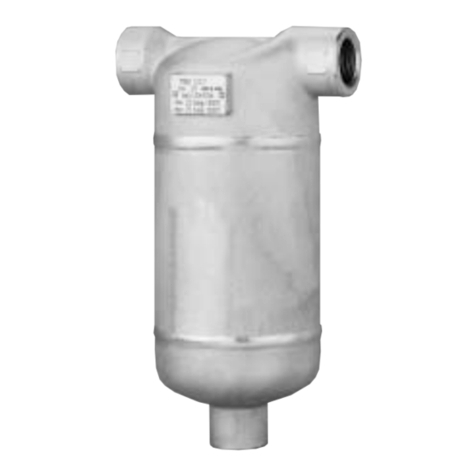
TLV DC3A User manual

Copyright (C) 2012 by TLV Co., Ltd. All rights reserved.
Deutsch
Polski
English
CYCLONE SEPARATOR TRAP
ZYKLON-ABSCHEIDER
DC3A/DC3S
DC3A/DC3S
INSTRUCTION MANUAL
EINBAU- UND BETRIEBSANLEITUNG
Keep this manual in a safe place for future reference
Gebrauchsanleitung leicht zugänglich aufbewahren
INSTRUKCJA OBSŁUGI
Należy przechowywać instrukcję w dostępnym miejscu
SEPARATOR CYKLONOWY Z
ODWADNIACZEM DC3A/DC3S

Introduction
Before beginning installation or maintenance, please read this manual to ensure correct use of the
product. Keep the manual in a safe place for future reference.
For use on mains and branches, the Cyclone Separator Traps use centrifugal force to separate
condensate from air or steam, and feature a built-in free float steam trap for the automatic
discharge of the collected condensate. The DC3A model is for air lines, the DC3S model is for
steam. (Do not use for toxic, flammable or otherwise hazardous fluids.)
1 MPa = 10.197 kg/cm2, 1 bar = 0.1 MPa
For products with special specifications or with options not included in this manual, contact TLV
for instructions.
The contents of this manual are subject to change without notice.
Einführung
Bitte lesen Sie die Betriebsanleitung vor Einbau und Inbetriebnahme sorgfältig durch und
bewahren Sie sie für späteren Gebrauch an einem leicht zugänglichen Ort auf.
Dieser Zyklonabscheider wird in Haupt- und Abzweigleitungen eingesetzt. Er nutzt die
Zentrifugalkraft zum Entfernen von Kondensat aus Dampf und Druckluftleitungen.
Der Abscheider hat einen eingebauten "Freischwimmer“ Kondensatableiter zur automatischen
Ableitung des angesammelten Kondensats. DC3A wird in Druckluftleitungen, DC3S in
Dampfleitungen eingebaut. (Nicht für giftige, entflammbare oder sonst wie gefährliche Fluide
benutzen.)
1 bar = 0,1 MPa
Wenden Sie sich an TLV für Sonderausführungen, die nicht in dieser Einbau- und
Betriebsanleitung enthalten sind
Wir behalten uns vor, den Inhalt dieser Betriebsanleitung ohne Ankündigung zu ändern.
Wstęp
Należy zapoznać się z tą instrukcją szczegółowo i stosować się do zawartych w niej
zaleceń.
DO stosowania na rurociągach głównych llub odnogach. Separator wykorzystuje siłę odśrodkową
od odseparowania drobin kondensatu oraz posiada wbudowany odwadniacz dla automatycznego
odprowadzania zbierającego się kondensatu. Model DC3A przeznaczony jest do powietrza,
model DC3S przeznaczony jest do pary wodnej ( Nie stosować do czynnikow wybuchowych ,
niebezpiecznych , żrących , palnych )
Dla specjalnych wersji lub nietypowych zastosowań prosimy o kontakt z firmą TLV
Zawartość instrukcji może się zmieniać bez uprzedniej informacji
―1―
Deutsch
Français
English

1. Safety Considerations
―2―
English
• Read this section carefully before use and be sure to follow the instructions.
• Installation, inspection, maintenance, repairs, disassembly, adjustment and valve
opening/closing should be carried out only by trained maintenance personnel.
• The precautions listed in this manual are designed to ensure safety and prevent equipment
damage and personal injury. For situations that may occur as a result of erroneous handling,
three different types of cautionary items are used to indicate the degree of urgency and the
scale of potential damage and danger: DANGER, WARNING and CAUTION.
• The three types of cautionary items above are very important for safety; be sure to observe
all of them, as they relate to installation, use, maintenance, and repair. Furthermore, TLV
accepts no responsibility for any accidents or damage occurring as a result of failure to
observe these precautions.
Indicates an urgent situation that poses a threat of death or serious injury.
Indicates a DANGER, WARNING or CAUTION item.
Indicates that there is a potential threat of death or serious injury.
WARNING
CAUTION
WARNING
DANGER
CAUTION Indicates that there is a possibility of injury, or equipment/product
damage.
NEVER apply direct heat to the float. The float may explode due to
increased internal pressure, causing accidents leading to serious injury
or damage to property and equipment.
Use hoisting equipment for heavy objects (weighing approximately
20 kg (44 lb) or more). Failure to do so may result in back strain or other
injury if the object should fall.
Take measures to prevent people from coming into direct contact
with product outlets. Failure to do so may result in burns or other injury
from the discharge of fluids.
When disassembling or removing the product, wait until the internal
pressure equals atmospheric pressure and the surface of the
product has cooled to room temperature. Disassembling or removing
the product when it is hot or under pressure may lead to discharge of
fluids, causing burns, other injuries or damage.
Be sure to use only the recommended components when repairing
the product, and NEVER attempt to modify the product in any way.
Failure to observe these precautions may result in damage to the product
or burns or other injury due to malfunction or the discharge of fluids.
Use only under conditions in which no freeze-up will occur. Freezing
may damage the product, leading to fluid discharge, which may cause
burns or other injury.
Use under conditions in which no water hammer will occur. The
impact of water hammer may damage the product, leading to fluid
discharge, which may cause burns or other injury.
Install properly and DO NOT use this product outside the recommended
operating pressure, temperature and other specification ranges.
Improper use may result in such hazards as damage to the product or
malfunctions, which may lead to serious accidents. Local regulations may
restrict the use of this product to below the conditions quoted.

―3―
Deutsch
1. Sicherheitshinweise
• Bitte lesen Sie dieses Kapitel vor Beginn der Arbeiten sorgfältig durch und befolgen Sie die
Vorschriften.
• Einbau und Ausbau, Inspektion, Wartungs- und Reparaturarbeiten, Öffnen/Schließen von
Armaturen, Einstellung von Komponenten, dürfen nur von geschultem Wartungspersonal
vorgenommen werden.
• Die Sicherheitshinweise in dieser Einbau- und Betriebsanleitung dienen dazu, Unfälle,
Verletzungen, Betriebsstörungen und Beschädigungen der Anlagen zu vermeiden. Für
Gefahrensituationen, die durch falsches Handeln entstehen können, werden drei verschiedene
Warnzeichen benutzt: GEFAHR; WARNUNG; VORSICHT.
• Diese drei Warnzeichen sind wichtig für Ihre Sicherheit. Sie müssen unbedingt beachtet werden,
um den sicheren Gebrauch des Produktes zu gewährleisten und Einbau, Wartung und
Reparatur ohne Unfälle oder Schäden durchführen zu können. TLV haftet nicht für Unfälle oder
Schäden, die durch Nichtbeachtung dieser Sicherheitshinweise entstehen.
bedeutet, dass eine unmittelbare Gefahr für Leib und Leben besteht.
Dieses Zeichen weist auf GEFAHR; WARNUNG; VORSICHT hin.
bedeutet, dass die Möglichkeit der Gefahr für Leib und Leben besteht.
WARNUNG
VORSICHT
WARNUNG
GEFAHR
VORSICHT
bedeutet dass die Möglichkeit von Verletzungen oder Schäden an
Anlagen oder Produkten besteht.
Die Schwimmerkugel darf NICHT ERHITZT werden, da sie infolge
erhöhten Innendruckes platzen kann, was schwere Unfälle und
Verletzungen oder Beschädigung von Anlagen zur Folge hat.
Für schwere Werkstücke (ca. 20 kg oder mehr) werden Hebezeuge
dringend empfohlen. Nichtbeachtung kann zu Rückenverletzungen oder
Verletzungen durch das herunterfallende Werkstück führen.
In sicherer Entfernung von Auslassöffnungen aufhalten und andere
Personen warnen, sich fernzuhalten. Nichtbeachtung kann zu
Verletzungen durch austretende Fluide führen.
Vor Öffnen des Gehäuses und Ausbau von Teilen warten, bis der
Innendruck sich auf Atmosphärendruck gesenkt hat und das
Gehäuse auf Raumtemperatur abgekühlt ist. Nichtbeachtung kann zu
Verbrennungen oder Verletzungen durch austretende Fluide führen.
Zur Reparatur nur Original-Ersatzteile verwenden und NICHT
VERSUCHEN, das Produkt zu verändern. Nichtbeachtung kann zu
Beschädigungen führen, die Betriebsstörungen, Verbrennungen oder
andere Verletzungen durch austretende Fluide verursachen.
Nur in frostsicherer Umgebung einsetzen. Einfrieren kann das Produkt
beschädigen, was zu Verbrennungen oder Verletzungen durch
austretende Fluide führt.
Nur an Stellen einbauen, an denen kein Wasserschlag eintreten
kann. Wasserschlag kann das Produkt beschädigen und zu
Verbrennungen oder Verletzungen durch austretende Fluide führen.
Die Einbauhinweise beachten und die spezifizierten Betriebsgrenzen
NICHT ÜBERSCHREITEN. Nichtbeachtung kann zu Betriebsstörungen
oder Unfällen führen. Lokale Vorschriften können zur Unterschreitung der
angegebenen Werte zwingen.

―4―
Polski
1. ZALECENIA BEZPIECZEŃSTWA
•
•
Należy zapoznać się z tą instrukcją szczegółowo i stosować się do zawartych w niej zaleceń.
•
• Montaż, Inspekcja, Obsługa, Naprawa, Demontaż oraz inne prace związane z otwieraniem i
zamykaniem zaworów powinny być wykonywane tylko przez przeszkolony personel
•Ostrzeżenia wymienione w niniejszym dokumencie zostały opracowane aby zapewnić
bezpieczeństwo, zapobiegać uszkodzeniom urządzeń oraz zranieniom osób obsługujących. Dla
sytuacji które mogą wystąpić w czasie błędnej obsługi, określono 3 główne typy zagrożeń i ich
oznaczenia w zależności od stopnia ryzyka wynikającego z uszkodzeń: ZAGROŻENIE,
OSTRZEŻENIE, UWAGA.
•
Trzy typy oznaczeń są bardzo ważne dla bezpieczeństwa i należy pamiętać aby zapoznać się z
nimi, gdyż dotyczą instalacji, stosowania, obsługi i naprawy. Firma TLV nie odpowiada za
jakiekolwiek wypadki i uszkodzenia wynikające z braku stosowania się do tych oznaczeń.
Sygnalizuje nagłą sytuację, która może grozić śmiercią lub
poważnym zranieniem
Sygnalizuje ZAGROŻENIE , OSTRZEŻENIE, UWAGA
Sygnalizuje potencjalne zagrożenie śmiercią lub poważnym zranieniem
UWAGA
OSTRZEŻENIE
ZAGROŻENIE
UWAGA
Sygnalizuje możliwość zranienia lub uszkodzenia urządzenia lub produktu
Należy prawidłowo instalować urządzenie. NIE WOLNO stosować urządzenia
przy parametrach spoza zakresu zalecanych ciśnień oraz temperatur pracy lub
innych ograniczeń podanych w specyfikacji urządzenia. Niewłaściwe
zastosowanie może prowadzić do uszkodzenia produktu, jego nieprawidłowej
pracy,a nawet może prowadzić do poważnych wypadków. Lokalne przepisy w
tym względzie mogą być bardziej restrykcyjne od podanych w spec yfikacjach.
Należy podjąć kroki aby zapobiegać możliwości pojawienia się osób w
zasięgu wylotu urządzenia.
Niestosowanie się do powyższego może prowadzić do oparzeń lub zranień na
skutek kontaktu z czynnikiem wypływającym z urządzenia.
Nie stosować nadmiernych sił podczas montażu urządzeń na połączeniach
gwintowych. Nadmierny moment może prowadzić do zerwania połączenia i
wydostania się czynnika na zewnątrz, co z kolei prowadzi do zagrożenia
oparzeniem lub innym zranieniem.
Podczas obsługi lub naprawy należy zawsze nosić odporne na temperatury
rękawice ochronne. Niestosowanie się może prowadzic do oparzeń.
Podczas demontażu oraz zdejmowania produktu z instalacji, należy
poczekać do momentu gdy ciśnienie wewnątrz urządzenia zrówna się z
ciśnieniem atmosferycznym i temperatura powierzchni urządzenia spadnie
do temperatury pokojowej.
Demontaż i zdejmowanie produktu z instalacji gdy jest gorące lub pod ciśnieniem
może prowadzić do wycieku czynnika powodując oparzenia lub uszkodzenia.
Należy upewnić się, że stosowane są tylko zalecane elementy do naprawy
urządzenia i NIGDY nie należy dokonywać modyfikacji urządzenia w jakikolwiek
sposób. Nie stosowanie się do powyższego może prowadzić do uszkodzeń
produktu, oparzeń lub innych zranień czy problemów z działaniem produktu oraz
wydostania się czynnika na zewnątrz.
Stosować w warunkach gdy nie występują uderzenia wodne. Uderzenia
wodne mogą doprowadzić do uszkodzenia urządzenia i w efekcie w ydostania się
czynnika na zewnątrz co z kolei prowadzi do zagrożenia oparzeniem lub innym
zranieniem.

―5―
Deutsch
Polski
English
2.
Configuration Aufbau Konfiguracja
w
w
65-100 mm
15-50 mm No.
1
2
3
4
5
6
7
8
9
10
11
12
Body
Separator
Separator Body
Trap Cover
Float
Float Cover
Plug*
Screen
Wave Spring
Body Gasket
Guide Pin
Body Bolt
DescriptionDescription
Cover Gasket
Baffle Nut
Baffle Bolt
Baffle
Float Cover Bolt
Spring Washer
Trap Valve Seat
Valve Seat Gasket
Bushing (DC3S)
Cover Bolt
Nameplate
No.
13
14
15
16
17
18
19
20
21
22
23
Nr.
1
2
3
4
5
6
7
8
9
10
11
12
Gehäuse
Abscheider
Abscheidergehäuse
Gehäusedeckel
Schwimmerkugel
Kugelgehäuse
Stopfen*
Schmutzsieb
Klemmfeder
Gehäusedichtung
Zentrierstift
Gehäuseschraube
BauteilBauteil
Deckeldichtung
Sechskantmutter
Sechskantschraube
Prellplatte
Sechskantschraube
Federring
KA-Ventilsitz
Prellplatte
Buchse (DC3S)
Deckelschraube
Typenschild
Nr.
13
14
15
16
17
18
19
20
21
22
23
No.
1
2
3
4
5
6
7
8
9
10
11
12
Korpus
Separator
Dolny korpus
Pokrywa
Pływak
Pokrywa
Korek*
Siatka filtra
Sprężyna
Uszczella
Kołek
Śruba
Opis Opis
Uszczelka
Nakrętka
Śruba
Płytka
Śruba
Podkładka spręż.
Gniazdo
Uszczelka
Tuleja (DC3S)
Śruba
Tabliczka
No.
13
14
15
16
17
18
19
20
21
22
23
!0
@1
@1
!5
!8
!8
!7
!7
!2
!2
!9
!9
o
q
y
y
t
t
i
i
u
!1
r
r
q
e
e
@2
@2
@3
@3
@0
@0
!3
!3
!1
!1
!1
!4
o
!0
!6
DC3S shown, DC3A has a trap valve seat with a rubber contact.
Gezeigt ist DC3S, DC3A hat eine Ventilsitzspitze aus Gummi.
DC3S pokazany , DC3A posiada gniazdo odwadniacza z gumą
* Option
* Option
*
Opcja

―6―
3.
Exploded View Einzelteile Widok
65-100 mm
( "- 4")
15-50 mm
( "- 2")
1
7
8
2
9
10
3
12
11
6
17
18
5
4
21
1
2
9
10
3
12
11
13
14
15
16
8
(65, 80 mm)
6
5
19
20
4
19
20
22
8
(100 mm)
(4")
11
17
18
22
11
2
1
/
2
( ", 3")
Deutsch
Polski
English
2
1
/
2
1
/
2

―7―
Deutsch
Français
English
4.
Specifications Technische Daten Dane techniczne
Refer to the product nameplate for detailed specifications.
Die technischen Daten stehen auf dem Typenschild.
Dokładna specyfikacja na tabliczce znamionowej
* Maximum allowable pressure (PMA) and maximum allowable temperature (TMA) are
PRESSURE SHELL DESIGN CONDITIONS, NOT OPERATING CONDITIONS.
** "Valve No." is displayed for products with options. This item is omitted from the
nameplate when there are no options.
* Maximal zulässiger Druck (PMA) und maximal zulässige Temperatur (TMA) sind
AUSLEGUNGSDATEN, NICHT BETRIEBSDATEN.
** Die "Valve No." wird angegeben bei Typen mit Optionen. Bei Typen ohne Optionen bleibt
diese Stelle frei.
*
Maksymalne dopuszczalne ciśnienie (PMA) oraz maksymalna dopuszczalna temperatura
(TMA) są parametrami korpusu z nie parametrami pracy.
** "Valne No" jest pokazane dla urządzenia z opcjami. Gdy nie ma opcji nie jest to pokazane na
tabliczce.
G Serial Number
Seriennummer
Numer seryjny
H Valve No.**
C Maximum Allowable Pressure*
Maximal zulässiger Druck*
Maksymalne dopuszczalne ciśnienie*
F Maximum Operating Temperature
Maximale Betriebstemperatur
Maksymalna temperatura pracy
D Maximum Allowable Temperature* TMA
Maximal zulässige Temperatur* TMA
Maksymalna dopuszczalna temperatura* TMA
A Model
Typ
Model
E Maximum Differential Pressure (at trap)
Maximaler Differenzdruck (am Kondensatableiter)
Maksymalna różnica ciśnień
B Nominal Diameter
Größe/DN
Wielkość/DN
B
A
G
D
E
H
C
F
To avoid malfunctions, product damage, accidents or serious injury,
install properly and DO NOT use this product outside the specification
range. Local regulations may restrict the use of this product to below the
conditions quoted.
Die Einbauhinweise beachten und die spezifizierten Betriebsgrenzen
NICHT ÜBERSCHREITEN. Nichtbeachtung kann zu Betriebsstörungen
oder Unfällen führen. Lokale Vorschriften können zur Unterschreitung der
angegebenen Werte zwingen.
VORSICHT
Installer le produit correctement et NE PAS l’utiliser en dehors des plages
spécifiées. En cas de dépassement des limites données, des dysfonc-
tionnements ou accidents pourraient survenir. Il se peut que des règle-
ments locaux limitent l'utilisation du produit en-deçà des spécifications
indiquées.
ATTENTION
CAUTION

Allowable Inclination
1. Before installation, be sure to remove all protective seals from the product.
2. Before installing the separator, blow out the inlet piping to remove any piping scraps, dirt and
oil. Close the inlet valve after blowdown.
3. Install the product at the point on the piping where the separation of condensate will have the
greatest effect on efficiency. For example, on a main or branch at the inlet of equipment
requiring high-quality dry air or steam.
4. Install the separator trap so the arrow on the product is pointing in the direction of flow.
5. The product should be inclined no more than 10˚ horizontally and front-to-back.
6. Install a main outlet valve and main outlet piping, and condensate outlet fittings and
condensate outlet piping.
7. To facilitate inspection and maintenance, install a union at the condensate outlet and ensure
that there is sufficient space for maintenance.
8. Open the inlet valve and outlet valves and check to make sure that the separator trap
functions properly
5. Proper Installation
• Installation, inspection, maintenance, repairs, disassembly, adjustment
and valve opening/closing should be carried out only by trained
maintenance personnel.
• Take measures to prevent people from coming into direct contact with product outlets.
• Install for use under conditions in which no freeze-up will occur.
• Install for use under conditions in which no water hammer will occur.
CAUTION
English
6. Operational Check
Normal: Condensate is discharged continuously with flash steam and the sound
of flow can be heard. If there is very little condensate, there is almost no
sound of flow.
Blocked: No condensate is discharged. The trap is quiet and makes no noise,
and the surface temperature of the trap is low.
Blowing: Live steam continually flows from the outlet and there is a continuous
metallic sound.
Live steam is discharged through the trap outlet together with the
condensate and there is a high-pitched sound.
A visual inspection can be carried out to aid in determining the necessity for immediate
maintenance or repair, if the trap is open to atmosphere. If the trap does not discharge to
atmosphere, use diagnostic equipment such as a stethoscope or thermometer. Operational
inspections should be performed at least twice per year, or as called for by trap operation
conditions as follows:
Check to see if steam or air is flowing from the separator outlet. Check all flow meters and check
differential pressure. If there is insufficient flow or differential pressure is too large, disassemble
and check for clogging of the screen. If the built-in trap should fail, it may cause damage to piping
and equipment resulting in faulty or low quality products or losses due to steam/air leakage.
Steam
Leakage:
Built-in Trap Operational Check
―8―

―9―
7. Inspection and Maintenance
WARNING
NEVER apply direct heat to the float. The float may explode due to
increased internal pressure, causing accidents leading to serious injury or
property and equipment damage.
• Installation, inspection, maintenance, repairs, disassembly, adjustment
and valve opening/closing should be carried out only by trained
maintenance personnel.
• Before attempting to open the separator, close the inlet and outlet isolation valves and wait
until the trap has cooled completely. Failure to do so may result in burns.
• Be sure to use the proper components and NEVER attempt to modify the product.
CAUTION
Body, Cover(s)
Gaskets
Screen
Float
Valve Seat
Check inside for damage, dirt, grease, oil film, rust or scale
Check for warping or damage
Check for clogging, corrosion or damage
Check for deformation, damage, oil film or water inside
Check for rust, scale, oil film, wear or damage
Parts Inspection Procedure
Disassembly / Reassembly (to reassemble, follow procedures in reverse)
Part & No. During Disassembly
15-50 mm
( "- 2")
65-100 mm
(2 "- 4")
During Reassembly
Cover Bolt 22
Trap Cover 4
Cover Gasket 13
Baffle Nut 14
Baffle 16
Screen 8
Float Cover Bolt 17
Spring Washer 18
Float Cover 6
Float 5
Trap Valve Seat 19
Valve Seat Gasket
20
Body Bolt 12
Separator Body 3
Separator 2
Screen 8
Wave Spring 9
Body Gasket 10
English
Use a wrench to remove
Pull down being careful not
to scratch seating surface
Remove gasket and clean
sealing surfaces
Use a wrench to remove
Remove
Be careful not to bend
Use a wrench to remove
Take off spring washer
Remove by lifting up and off
Remove being careful not to
scratch the polished surface
Use a wrench to remove
Remove gasket and clean
sealing surfaces
Use a wrench to remove
Pull down and out, be careful
not to let the separator fall out
Remove when detaching
the separator body
Be careful not to bend
Remove with separator
Remove gasket and clean
sealing surfaces
Coat threads with anti-seize,
tighten to the proper torque
Remove all pieces of the old
gasket from sealing surfaces,
use guide pin to aid alignment
Replace with a new gasket
Coat threads with anti-seize,
tighten to the proper torque
Reattach
Place on top of float cover
Coat threads with anti-seize,
tighten to the proper torque
Reattach spring washer
Place into position
Insert being careful not to
scratch or misshape
Coat threads with anti-seize,
tighten to the proper torque
Replace with a new gasket
Coat threads with anti-seize,
tighten to the proper torque
Reattach, use guide pin for
alignment
Insert into groove in the
separator body
Place on top of the separator
Insert into groove
Replace with new gasket
◯ ◯
◯ ◯
◯ ◯
◯
◯ ◯
◯
◯
◯ ◯
◯ ◯
◯ ◯
◯ ◯
◯ ◯
◯ ◯
◯ ◯
◯ ◯
◯
◯ ◯
◯ ◯
2
1
/
2
1
/

―10―
15 - 40
50 - 80
100
15 - 40
50 - 80
100
15, 20
25, 40
50 - 80
100
15, 20
25, 40
50 - 100
65, 80
100
60
70
160
60
70
160
10
15
40
50
7
10
20
10
20
(44)
(51)
(115)
(44)
(51)
(115)
(7)
(11)
(29)
(37)
(5)
(7)
(15)
(7)
(15)
( )
( )
( )
( )
( )
( )
( )
( )
( )
( )
( )
( )
( )
( )
( )
17
19
24
17
19
24
11
13
17
19
8
10
13
10
13
60
70
160
60
70
160
15
40
50
10
20
10
20
(44)
(51)
(115)
(44)
(51)
(115)
(11)
(29)
(37)
(7)
(15)
(7)
(15)
17
19
24
17
19
24
13
17
19
10
13
10
13
( " - 1 ")
(2" - 3")
(4")
( " - 1 ")
(2"- 3")
(4")
( ", ")
(1",1 ")
(2"- 3")
(4")
( ", ")
(1",1 ")
(2"- 4")
(2 ", 3")
(4")
Torque
English
Tightening Torque and Distance Across Flats
Problem Cause Remedy
8. Troubleshooting
If the expected performance is unachievable after installation of the separator, read chapters 5 and
6 again and check the following points to take appropriate corrective measures.
No condensate is
discharged or
discharge is poor
(blocked)
Steam or air is
discharged or leaks
from the trap outlet
(blowing) (steam or air
leakage)
Steam or air is leaking
from sealing surfaces
Water is mixed with
the steam or air at the
separator outlet
Separator outlet
pressure drops or
desired flow rate is
unachievable
Float is damaged or filled with condensate
Trap valve seat port, screen [65-100 mm (2 "
-4")] or piping is clogged with rust or scale
The trap operating pressure exceeds the
maximum specified pressure, or there is
insufficient pressure differential between the
trap inlet and outlet
Rust and scale have accumulated around the
trap valve seat or under the float
The trap valve seat is damaged
Float is deformed or coated with scale
Separator is installed above the maximum
allowable inclination angle
Deterioration of or damage to gaskets
Improper tightening torques were used
Steam or air flow velocity is too high
Review causes listed above in "No
condensate is discharged…"
The screen [15-50 mm ( "-2")] is clogged
with rust or scale
Replace the float
Clean
Compare specifications and
actual operating conditions
Clean
Replace with a new trap valve seat
Clean or replace the float
Correct the installation
Replace with new gaskets
Tighten to the proper torque
Take steps necessary to lower
the air or steam flow velocity
Follow appropriate remedy
Clean or replace the screen
DC3S DC3A
Model
(lbf•ft)
Part &
No.
Body
Bolt 12
Baffle
Nut 14
Cover
Bolt 22
Trap
Valve
Seat 19
Float
Cover
Bolt 17
Model Size
mm N•m
Torque
(lbf•ft)
N•m
Distance
Across Flats
(in)
mm
Distance
Across Flats
(in)
mm(in)
2
1
/
2
1
/
32
21
/
32
21
/
32
21
/
16
15
/
16
15
/
4
3
/
4
3
/
2
1
/
8
3
/
8
3
/
2
1
/
2
1
/
2
1
/
2
1
/
4
3
/
16
7
/
16
5
/
( )
( )
( )
( )
( )
( )
( )
( )
( )
( )
( )
( )
( )
32
21
/
32
21
/
32
21
/
16
15
/
16
15
/
4
3
/
4
3
/
2
1
/
8
3
/
8
3
/
2
1
/
2
1
/
4
3
/
2
1
/
2
1
/
2
1
/
2
1
/
4
3
/
2
1
/
2
1
/
4
3
/
2
1
/

5. Einbauhinweise
VORSICHT
Deutsch
―11―
6. Funktionsprüfung
Schräglagentoleranz
1. Vor dem Einbau die Transport-Schutzkappen entfernen.
2. Vor Einbau Leitung durchblasen, um Öl und Verschmutzungen zu entfernen. Danach ist die
Absperrarmatur vor dem Abscheider zu schließen.
3. Den Zyklonabscheider an Stellen einbauen wo Kondensat erwartet wird und dessen
Abscheidung den größten Effekt auf den Wirkungsgrad der Leitung hat, z.B. in einer Haupt-
oder Abzweigleitung und am Einlass von Anlagen, die Dampf, Luft oder Gase mit hoher
Trockenheit benötigen.
4. Der Pfeil auf dem Gehäuse muss in Durchflussrichtung zeigen.
5. Zyklonabscheider so einbauen, dass die nachfolgend gezeigten Schräglagentoleranzen nicht
überschritten werden.
6. An der Auslassseite des Zyklonabscheiders ein Absperrorgan in die Hauptleitung einbauen und
am Kondensatauslass eine Kondensatleitung anschließen.
7. Zur Erleichterung von Wartung und Reparatur sollte am Kondensatauslass eine Rohrver-
schraubung angebracht und genügend Platz für Wartungsarbeiten vorgesehen werden.
8. Nach Beendigung der Montagearbeiten Einlass und Auslassarmaturen öffnen und die Funktion
des Ableiters überprüfen.
Überprüfung des eingebauten Kondensatableiters
• Einbau und Ausbau, Inspektion, Wartungs- und Reparaturarbeiten,
Öffnen/Schließen von Armaturen, Einstellung von Komponenten dürfen
nur von geschultem Wartungspersonal vorgenommen werden.
• In sicherer Enfernung von Auslassöffnungen aufhalten und andere Personen warnen, sich fern
zu halten.
• Zyklonabscheider in frostsicherer Umgebung einbauen .
• Zyklonabscheider nur dort einbauen, wo kein Wasserschlag eintreten kann.
Falls der Kondensatableiter das Kondensat ins Freie abführt, können visuelle Inspektionen einen
Hinweis geben, ob sofortige Wartung oder Reparatur notwendig ist. An Kondensatrückführ-
leitungen angeschlossene Kondensatableiter können mit geeigneten Messgeräten, z. B.
Stethoskop oder Thermometer geprüft werden. Es wird empfohlen, mindestens zweimal pro Jahr
oder, je nach Betriebsweise, in kürzeren Zeitabständen eine Inspektion durchzuführen.
An den Durchflussmessern prüfen, ob Dampf oder Luft durch den Abscheider fließt. Auch den
Differenzdruck überprüfen. Falls ungenügender Durchfluss oder zu hoher Differenzdruck
festgestellt wird, Zyklonabscheider öffnen und das Schmutzsieb auf Verstopfung überprüfen.
Fehler am eingebauten Kondensatableiter können Beschädigungen an den Rohrleitungen oder
Anlagen verursachen, die zu fehlerhaften Produkten oder Dampf-/ Luftverlust führen.
Normal: Kondensat wird kontinuierlich unter Bildung von Entspannungsdampf
abgeleitet. Ein entsprechendes Fließgeräusch ist zu hören. Bei geringer
Kondensatmenge ist dieses Geräusch ebenfalls geringer, oder kaum noch
wahrnehmbar.
Blockiert: Kondensatabfluss nicht feststellbar. Der KA macht kein Geräusch und seine
Oberflächentemperatur ist niedrig.
KA bläst: Sattdampf tritt kontinuierlich an der Auslassseite aus und ein metallisch
klingendes Geräusch ist hörbar.
Dampfverlust: Sattdampf, vermischt mit Kondensat tritt mit einem pfeifenden Geräusch
an der Auslassseite aus.

Gehäuse, Deckel
Dichtungen
Schmutzsieb
Schwimmerkugel
Ventilsitz
Auf Ablagerungen, Rost, Schmutz, Ölfilm prüfen
Auf Verformung oder Beschädigung prüfen
Auf Verstopfung, Ablagerungen, Beschädigung prüfen
Auf Verformung, Beschädigung oder Wasser in der Kugel prüfen
Auf Ablagerungen, Rost, Schmutz, Ölfilm prüfen
Überprüfung der Einzelteile
7. Inspektion und Wartung
WARNUNG
Um Unfälle und Verletzungen zu vermeiden, darf die Schwimmerkugel
NICHT ERHITZT WERDEN, da sie infolge erhöhten Innendrucks platzen
kann.
• Einbau und Ausbau, Inspektion, Wartungs- und Reparaturarbeiten,
Öffnen/Schließen von Armaturen, Einstellung von Komponenten dürfen
nur von geschultem Wartungspersonal vorgenommen werden.
• Vor dem Öffnen des Zyklonabscheiders sind die Absperrarmaturen auf beiden Seiten zu
schließen. Gehäuse auf Raumtemperatur abkühlen lassen. Nichtbeachtung kann zu
Verbrennungen führen
• Zur Reparatur nur Original-Ersatzteile verwenden und NICHT VERSUCHEN, das Produkt zu
verändern.
VORSICHT
Deutsch
―12―
Ausbau und Einbau der Teile (Einbau erfolgt in umgekehrter Reihenfolge)
Bauteil & Nr. Ausbau
DN
15-50 DN
65-100 Einbau
Deckel-
schraube 22
Gehäusedeckel 4
Deckeldichtung 13
Sechskant-
mutter 14
Prellplatte 16
Schmutzsieb 8
Sechskant-
schraube 17
Federring 18
Kugelgehäuse 6
Schwimmerkugel 5
KA-Ventilsitz 19
Ventilsitz-
dichtung 20
Gehäuse-
schraube 12
Abscheider-
gehäuse 3
Abscheider 2
Schmutzsieb 8
Klemmfeder 9
Gehäuse-
dichtung 10
Gabel- oder Ringschlüssel
verwenden
Nach unten abnehmen,
Dichtflächen nicht
zerkratzen
Dichtung abnehmen,
Dichtflächen reinigen
Gabel- oder Ringschlüssel
verwenden
Prellplatte abheben
Vorsicht, nicht verbiegen
Gabel- oder Ringschlüssel
verwenden
Federring abnehmen
Nach oben abheben
Herausnehmen, feinge-
schliffene Oberfläche nicht
zerkratzen
Gabel- oder Ringschlüssel
verwenden
Dichtung abnehmen,
Dichtflächen reinigen
Gabel- oder Ringschlüssel
verwenden
Nach unten herausneh-
men, nicht fallen lassen
Mit Abscheidergehäuse
abnehmen
Vorsicht, nicht verbiegen
Mit Abscheider abnehmen
Dichtung abnehmen,
Dichtflächen reinigen
Mit Schmiermittel bestreichen,
Anzugsmoment beachten
Reste alter Dichtung entfernen,
Zentrierstift in Bohrung im
Abscheidergehäuse einstecken
Dichtung erneuern
Mit Schmiermittel bestreichen,
Anzugsmoment beachten
Prellplatte aufsetzen
Auf Kugelgehäuse auflegen
Mit Schmiermittel bestreichen,
Anzugsmoment beachten
Federring einsetzen
Aufsetzen und anschrauben
Einsetzen, feingeschliffene
Oberfläche nicht zerkratzen
Mit Schmiermittel bestreichen,
Anzugsmoment beachten
Dichtung erneuern
Mit Schmiermittel bestreichen,
Anzugsmoment beachten
Zentrierstift in die Bohrung im
Abscheidergehäuse einstecken
In Rille im Abscheidergehäuse
einsetzen
Auf Abscheider auflegen
In Rille einsetzen
Dichtung erneuern
◯ ◯
◯ ◯
◯ ◯
◯
◯
◯
◯ ◯
◯ ◯
◯ ◯
◯ ◯
◯ ◯
◯ ◯
◯ ◯
◯ ◯
◯ ◯
◯
◯
◯
◯ ◯

Deutsch
Kondensat läuft
nicht ab, oder
Ableitung ist
ungenügend
(blockiert)
Schwimmerkugel ersetzen
Reinigen
Schmutzsieb reinigen oder ersetzen
Dichtungen sind abgenutzt oder
beschädigt Dichtungen ersetzen
Anzugsmoment von
Gehäuseschrauben zu gering Mit vorgeschriebenem
Anzugsmoment anziehen
KA-Ventilsitz ist beschädigt KA-Ventilsitz ersetzen
Schwimmerkugel ist beschädigt oder
verschmutzt Schwimmerkugel reinigen oder
ersetzen
Reinigen
8. Fehlersuche
Falls der Zyklonabscheider nicht zufriedenstellend arbeitet, lesen Sie nochmals Kapitel 5 und 6.
Gehen Sie dann die nachfolgende Fehlerliste durch, um den Fehler zu orten und zu korrigieren.
Symptom Ursachen Gegenmaßnahmen
Größe
DN
15 - 40
50 - 80
100
15 - 40
50 - 80
100
15, 20
25, 40
50 - 80
100
15, 20
25, 40
50 - 100
65, 80
100
Anzugsmomente und Schlüsselweiten
DC3S DC3A
60
70
160
60
70
160
10
15
40
50
7
10
20
10
20
Anzugsmoment
N•m
17
19
24
17
19
24
11
13
17
19
8
10
13
10
13
Schlüsselweite
mm
60
70
160
60
70
160
15
40
50
10
20
10
20
Anzugsmoment
N•m
17
19
24
17
19
24
13
17
19
10
13
10
13
Schlüsselweite
mm
Schwimmerkugel ist beschädigt, oder
voll Wasser
KA-Ventilsitz, Schmutzsieb (DN 65
-
100)
oder Rohrleitungen sind verstopft mit
Schmutzablagerungen oder Rost
KA-Ventilsitz ist verstopft, oder Rost und
Schmutz haben sich unter der
Schwimmerkugel abgelagert
Der Betriebsdruck des KA übersteigt den
maximal zulässigen Druck oder der
Differenzdruck zwischen Einlass und
Auslass ist zu niedrig
Prüfen, ob Auslegungsdaten mit den
wirklichen Betriebsdaten
übereinstimmen
Dampf- oder
Luftverlust über
die Kondensat-
auslassleitung
(KA bläst)
Dampf oder Luft-
leckage aus
Gehäuse
Dampf oder Luft im
Auslass des Ab-
scheiders ist ver-
mischt mit
Kondensat
Druckverlust nach
Abscheider oder
ungenügender
Durchfluss
Zyklonabscheider ist in zu großer
Schräglage eingebaut Abscheider innerhalb der
Schräglagentoleranz einbauen
Dampf- oder Luft-
Durchflussgeschwindigkeit ist zu hoch Durchflussgeschwindigkeit durch
entsprechende Maßnahmen
reduzieren
Ursachen unter "Kondensat läuft nicht
ab…" in Betracht ziehen Gegenmaßnahmen unter "Kon-
densat läuft nicht ab… " treffen
Das Schmutzsieb (DN 15 - 50) ist
verstopft mit Schmutzablagerungen
oder Rost
―13―
Typ
Bauteil & Nr.
Gehäuse-
schraube 12
Deckel-
schraube 22
KA-Ventil-
sitz 19
Sechskant-
schraube 17
Sechskant-
mutter 14

―14―
Polski
Możliwe odchylenie
1.Przed instalacją nalezy zdjąć zatyczki ochronne z urządzenia
2.Przed instalację należy przedmuchać i oczyścić rurociągi z zabrudzel. Po przedmuchu
zamknąć zawór dolotowy.
3. Zamotnować urządzenie w miejscu gdzie separacja kondensatu będzie miała najwyższą
efektywność. Np na głównym rurociągu lub odnodze przed urządzeniem które wymaga czystej
suchej pary.
Zamontować separator tak aby strzałka na odwadniaczu zgadza się z kierunkiem przepływu .
4.
5.Odchylenie urządzenia nie może przekraczać 10 stopni. Patrz rysunek poniżej
6.Zamontować zawopry po stronie wylotowej , rurociąg wylotowy , oraz rurociąg
odprowadzania kondensatu
7.Dla ułatwienia demontażu na rurce odwadniającej zaleca się montaż złączki.
8. Otworzyć zawór dolotwy oraz wylotowy i sprawdzić czy separator pracuje w sposób
prawidłowy
5. Właściwa instalacja
•Instalacja , inspekcja , obsługa i naprawa , demontaż i montaż powinny
być przeprowadzane tylko przed przeszkolony personel.
•Należy upewnić się że żadne osoby nie znajdują się od strony wylotu z urządzenia
•Należy zabezpieczyc urządzenie przed zamarzaniem
•Należy upewnić się że w systemie nie występuja uderzenia wodne
UWAGA
6. Kontrola działania
Normalna:Kondensat odprowadzany jest w sposób ciągły w obłokami pary wtórnej i
słychać przepływ. Jeżeli jest mały przepłwy kondensatu jest on prawie
niesłyszalny.
Zablokowany:Brak odprowadzania kondensatu. Nie słychać odwadniacza i jego
powierzchnia ma niską temperaturę.
Przedmuch:Żywa para przecieka przez odwadniacz z ciągłym metalicznym
dźwiękiem.
Żywa para przedostaje się razem z odprowadzanym kondensatem
i towarzyszy temu wysoki dźwięk
Wizualna inspekcja może być przeprowadzona aby stwierzdić konieczność ewentualnej naprawy
lub obsługi jeżeli odwadniacz odprowadza do atmosfery. Jeżeli odwadniacz odprowadza do
rurociągu nalezy skorzystać z urządzenia diagnostycznego (Testera) lub termometru .
Sprawdzenie działania powinno być przeprowadzane 2 razy w roku, lub na podstawie warunków
pracy :
Sprawdzić czy para lub powietrze przepływa przez separator. Sprawdzić przepływomierze oraz
spadek ciśnienia na separatorze. Wzrost spadku ciśnienia pokazuje możliwość zabrudzenia siatki
filtra i konieczności jej oczyszczenia. Jeżeli odwadniacz się zepsuje może prowadzić to do
niewłaściwej pracy całego separatora i wpływu na jakosć dostarczanej pary a tym samym produktu
końcowego.
Przeciek
Pary:
Kontrola działania odwadniacza

Polski
―15―
7. Inspekcja i obsługa
UWAGA
NIGDY nie poddawać pływaka oddziaływaniu ciepła. Pływak może
eksplodować powodują zranienia lub wypadki personelu lub otoczenia.
•Montaż, Inspekcja, Obsługa, Naprawa, Demontaż oraz inne prace
związane z otwieraniem i zamykaniem zaworów powinny być
wykonywane tylko przez przeszkolony personel
• Przed przystapieniem do demontazu nalezy upewnić się że zawory odcinające sa
zamkniete i szczelne oraz separator ostygł całkowicie. Zagrożenie oparzeniami
•Należy stosować tylko oryginalne części i nie modyfikować produktu.
CAUTION
Korpus , pokrywa
Uszczelki
Siatka filtra
Pływak
Gniazdo odwadniacza
Procedura inspekcji częsci
Sprawdzić powierzchnie pod kątem uszkodzeń , zabrudzeń
Sprawdzić pod kątem uszkodzeń
Sprawdzić czy nie jest zanieczyszczona
Sprawdzić czy nie posiada uszkodzęń , deformacji
Sprawdzić pod kątem zabrudzeń , uszkodzeń
Demontaż / Montaż ( do ponownego montażu stosować procedurę odwrtonie)
Podczas demontażu
15-50 mm
65-100 mm
Część & Nr.
( "- 2")
(2 "- 4")
Podczas montażu
Śruba pokrywy 22
Trap Cover 4
Cover Gasket 13
Baffle Nut 14
Baffle 16
Screen 8
Float Cover Bolt 17
Spring Washer 18
Float Cover 6
Float 5
Trap Valve Seat 19
Valve Seat Gasket
20
Body Bolt 12
Separator Body 3
Separator 2
Screen 8
Wave Spring 9
Body Gasket 10
Odkręcić kluczem
Zdjąć uważając aby nie
uszkodzić przylgi
Zdjąć uszczelki i oczyscić
powierzchnię
Odkręcić kluczem
Zdjąć
Uważać aby nie powyginać
Odkręcić kluczem i zdjąć
Zdjąc podkładkę
Zdemontować
Wyjąć uważnie aby nie
uszkodzić powierzchni
Odkręcić kluczem
Zdjąć uszczelki i oczyscić
powierzchnię
Odkręcić kluczem
Pociągnąć w dół , uważać aby
nie wypadł
Zdjąć gdy odłączamy
korpus separatora
Uważać aby nie wygiąć
Zdjąć z separatorem
Zdjąć uszczelki i oczyscić
powierzchnię
Pokryć gwint środkiem i
dokręcić z momentem
Usunąć pozostałości starych
uszczelek oraz oczyścić
powierzchnie i założyć nowe
uszczelki
Pokryć gwinty środkiem i
dokręcić z momentem
Nałożyć
Place on top of float cover
Pokryć gwinty środkiem i
dokręcić z momentem
Założyć podkładkę
Włożyć na miejsce
Włożyć ostrożnie
Pokryć gwinty środkiem i
dokręcić z momentem
Założyć nową uszczelkę
Pokryć gwinty środkiem i
dokręcić z momentem
Nałożyć korzystając z kołka
ustalającego
Włozyć w rowek korpusu
Nałożyć na separator
Włożyć w rowek
Założyć nową uszczelkę
◯ ◯
◯ ◯
◯ ◯
◯
◯ ◯
◯
◯
◯ ◯
◯ ◯
◯ ◯
◯ ◯
◯ ◯
◯ ◯
◯ ◯
◯ ◯
◯
◯ ◯
◯ ◯
1
/
2
1
/
2

―16―
Polski
15 - 40
50 - 80
100
15 - 40
50 - 80
100
15, 20
25, 40
50 - 80
100
15, 20
25, 40
50 - 100
65, 80
100
60
70
160
60
70
160
10
15
40
50
7
10
20
10
20
(44)
(51)
(115)
(44)
(51)
(115)
(7)
(11)
(29)
(37)
(5)
(7)
(15)
(7)
(15)
(
(
(
(
( )
(
( )
( )
17
19
24
17
19
24
11
13
17
19
8
10
13
10
13
60
70
160
60
70
160
15
40
50
10
20
10
20
(44)
(51)
(115)
(44)
(51)
(115)
(11)
(29)
(37)
(7)
(15)
(7)
(15)
17
19
24
17
19
24
13
17
19
10
13
10
13
(2" - 3")
(4")
(2"- 3")
(4")
(2"- 3")
(4")
(2"- 4")
(2 ", 3")
(4")
Moment
Problem
8. Problemy
Jeżeli spodziewana jakosć działania nie jest osiągana nalezy zapoznać się z par 5 oraz 6 dla
podjęcia odpowiednich działań.
Kondensat
nie jest
odprowadzany lub
bardzo słabo.
zablokowany
Para lub powietrze
przedostaje sie przez
odwadniacz na
zewnątrz
Steam or air is leaking
from sealing surfaces
Water is mixed with
the steam or air at the
separator outlet
Separator outlet
pressure drops or
desired flow rate is
unachievable
Przyczyna
Pływak jest uszkodzony
Gniazdo odwadniacza jest zatkane , filtr
[65-100 mm (2 "
1
/
2
-4")] lub rurociąg jest
zatkany. Ciśnienie przekracza maksymalną
różnicę ciśnień lub różnica jest zbyt mała
popmiędzy dollotem do odwadniacza i wylotem.
Rdza lub zabrudzenia osiadły na gnieździe lub
pod pływakiem.
Gniazdo jest uszkodzone
Pływak jest uszkodzony lub pokryty rdzą
Separator jest zamontowany z większym,
odchyleniem niż dopuszczalne
Uszkodzenia uszczelek
Niewłaściwy moment dokręcania śrub
Zbyt duży przepływ pary lub powietrza
Sprawdzić listę pprzyczyn : Brak
odprowadzania kondensatu...
Filtr [15
1
/
2
-50 mm ( "-2")] jest
zanieczyszczony rdzą lub innymi
zabrudzeniami
Korekta
Wymienić pływak
Oczyścić
Sprawdzić specyfikację z
parametrami pracy
Oczyścić
Wymienić na nowe
Oczyścić lub wymienić
Poprawić sposó montażu
Wymienić uszczelki
Dokręcić odpowiednim
momentem
Podjąć kroki aby zmniejszyć
przepływy
Znaleźć odpowiednie
rozwiązanie
Oczyśccić lub wymienić filtr
Rozmiary klucza oraz wartości momentów
DC3S DC3A
Model
(lbf•ft)
Część &
NR.
Korpus
Śruba 12
Kier.
Nakr.14
Pokrywa
Śruba 22
Gniazdo
odwad.
19
Śruba
pokrywy
odwad17
Wielkość
mm N•m
Moment
(lbf•ft)
N•m
Rozstaw
Klucza
(in)
mm
Rozstaw
Klucza
(in)
mm(in)
1
/
2
( " - 1 ")
1
/
221
(
/
32
21
(
/
32
21
(
/
32
15
(
/
16
15
(
/
16
3
( )
/
4
3
( )
4
/
1
( )
2
/
3
/
8
3
( )
8
/
1
( )
2
/
1
( )
2
/
3
( )
4
/
7
/
16
5
/
16
(
(
(
(
(
21
(
/
32
21
(
/
32
21
(
/
32
15
(
/
16
15
(
/
16
3
( )
/
4
3
( )
4
/
1
( )
2
/
3
( )
8
/
3
( )
8
/
1
( )
2
/
1
( )
2
/
3
( )
4
/
1
/
2
(1",1 ")
12
/
(1",1 ")
12
/
(3
", ")
/
4
1
/
2
1
/
2
(3
", ")
/
4
1
/
2
( " - 1 ")
1
/
2

Deutsch
Français
English
―17―
9. Product Warranty
9.
Gwarancja
9. Garantie
1) Garaniezeit: Ein Jahr nach Lieferung.
2) Falls das Produkt innerhalb der Garantiezeit, aus Gründen die TLV CO., LTD. zu vertreten
hat, nicht der Spezifikation entsprechend arbeitet, oder Fehler an Material oder Verarbeitung
aufweist, wird es kostenlos ersetzt oder repariert.
3) Von der Produktgarantie ausgenommen sind kosmetische Mängel sowie Beschädigungen
des Produktäußeren. Die Garantie erlischt außerdem in den folgenden Fällen:
1. Schäden, die durch falschen Einbau oder falsche Bedienung hervorgerufen werden.
2. Schäden, die durch Verschmutzungen, Ablagerungen oder Korrosion usw. auftreten.
3. Schäden, die durch falsches Auseinandernehmen und Zusammenbau, oder ungenügende
Inspektion und Wartung entstehen.
4. Schäden verursacht durch Naturkatastrophen und Unglücksfälle.
5. Unglücksfälle und Schäden aus anderen Gründen, die von TLV CO., LTD. nicht zu
vertreten sind.
4) TLV CO., LTD. haftet nicht für Folgeschäden.
1) Warranty Period: one year after product delivery.
2) TLV CO., LTD. warrants this product to the original purchaser to be free from defective
materials and workmanship. Under this warranty, the product will be repaired or replaced at
our option, without charge for parts or labor.
3) This product warranty will not apply to cosmetic defects, nor to any product whose exterior
has been damaged or defaced; nor does it apply in the following cases:
1. Malfunction due to improper installation, use, handling, etc., by other than TLV CO., LTD.
authorized service representatives.
2. Malfunctions due to dirt, scale, rust, etc.
3. Malfunctions due to improper disassembly and reassembly, or inadequate inspection and
maintenance by other than TLV CO., LTD. authorized service representatives.
4. Malfunction due to disasters or forces of nature.
5. Accidents or malfunctions due to any other cause beyond the control of TLV CO., LTD.
4) Under no circumstances will TLV CO., LTD. be liable for consequential economic loss or
damage or consequential damage to property.
1)Okres gwarancji wynosi 12 miesięcy
2) TLV CO., LTD. gwarantuje że produkt jest jest oryginalny i wolny od wad materiałowych i
produkcyjnych. Na gwarancji produkt zostanie naprawiony lub wymieniony bez opłat za
robociznę oraz części,
3)Gwarancja nie obejmuje kosmetycznych defektów , lub urządzeń które noszę zewnętrzne ślady
uszkodzeń oraz w następujących przypadkach :
1. Problemy w działaniu na skutek nieprawidłowego montażu , zastosowania obsługi etc.,
przez inny personel niż TLV lub ich autoryzowanych przedstawicieli
2.Problemy w działaniu na skutek zabrudzęń.
3. Problemy w działaniu na skutek nieprawidłowego demontażu i montażu przez inny personel
niż TLV lub ich autoryzowanych przedstawicieli
4.Problemy w działaniu na skutek sił natury
5.Wypadki lub problemy w działniu spowodowane czynnikami poza wpływem firmy TLV
4)W żadnym wypadku firma TLV nie odpowiada za strtay ekonomiczne , uszkodzenia
mienia na skutek nieprawidłowej pracy urzadzenia

―18―
Für Reparatur und Wartung:
Wenden Sie sich bitte an Ihre Vertretung oder an eine der Niederlassungen.
For Service or Technical Assistance:
Contact your representative or your regional office.
Pour tout service ou assistance technique:
Contactez votre agent ou votre bureau régional .
USA and Canada:
USA und Kanada:
E.U. et le Canada:
13901 South Lakes Drive, Charlotte,
NC 28273-6790, U.S.A.
Tel: [1]-704-597-9070
Fax: [1]-704-583-1610
Mexico:
Mexiko:
Mexique:
San Andr
é
s Atoto No. 12, Col. San Andr
é
s Atoto 53500,
Naucalpan, Edo. de México, Mexico
Tel: [52]-55-5359-7949
Fax: [52]-55-5359-7585
Argentina:
Argentinien:
Argentine:
Av. Mitre 775, B1603CQH Villa Martelli,
Pcia. Buenos Aires, Argentina
Tel: [54]-(0)11-4760-8401
Fax: [54]-(0)11-4761-6793
Europe:
Europa:
Europe:
Daimler-Benz-Straße 16-18,
74915 Waibstadt, Germany
Tel: [49]-(0)7263-9150-0
Fax: [49]-(0)7263-9150-50
Star Lodge, Montpellier Drive, Cheltenham,
Gloucestershire GL50 1TY, U.K.
Tel: [44]-(0)1242-227223
Fax: [44]-(0)1242-223077
United Kingdom:
Großbritannien:
Royaume Uni:
France:
Frankreich:
France:
Parc d’Ariane 2, bât. C, 290 rue Ferdinand Perrier,
69800 Saint Priest, France
Tel: [33]-(0)4-72482222
Fax: [33]-(0)4-72482220
Oceania:
Ozeanien:
Océanie:
Unit 22, 137-145 Rooks Road, Nunawading,
Victoria 3131, Australia
Tel: [
61
]-(
0)3-9873 5610
Fax: [
61
]-(
0)3-9873 5010
66 Tannery Lane, #03-10B Sindo Building,
Singapore 347805
Southeast Asia:
Südostasien:
Asie du Sud-Est:
Tel: [65]-6747 4600
Fax: [65]-6742 0345
Room 1306, No. 103 Cao Bao Road,
Shanghai, China 200233
China:
China:
Chine:
Tel: [86]-21-5102-1669
Fax: [86]-21-6482-8623
Malaysia:
Malaysien:
Malaisie:
8 & 8A, Jalan BP 6/6, Bandar Bukit Puchong,
47120 Puchong, Selangor, Malaysia
Tel: [60]-3-8065-2928
Fax: [60]-3-8065-2923
Korea:
Korea:
Corée:
#302-1 Bundang Technopark B, Yatap, Bundang,
Seongnam, Gyeonggi, 463-760 Korea
Tel: [82]-(0)31-726-2105
Fax: [82]-(0)31-726-2195
881 Nagasuna, Noguchi, Kakogawa,
Hyogo 675-8511, Japan
Other countries:
Andere Länder:
Autres pays:
Tel: [81]-(0)79-427-1818
Fax: [81]-(0)79-425-1167

Rev. 9/2012 (M)
Printed on recycled paper.
Auf Recycling-Papier gedruckt.
Imprimé sur du papier recyclé.
881 Nagasuna, Noguchi, Kakogawa,
Hyogo 675-8511, Japan
Manufacturer:
Hersteller:
Fabricant:
Tel: [81]-(0)79-422-1122
Fax: [81]-(0)79-422-0112
Other manuals for DC3A
1
This manual suits for next models
1
Table of contents
Other TLV Water Filtration System manuals
Popular Water Filtration System manuals by other brands

Grayl
Grayl Legend owner's manual

Bühler technologies
Bühler technologies FGSL Series Installation and operation instruction

Sicce
Sicce Tidal 55 owner's manual

EcoWater
EcoWater ETF2100 PF owner's manual

DEHOUST
DEHOUST Watermanager GWM 500 inhouse Installation and commissioning manual

Hayward
Hayward S210SLE owner's manual

AQUAPHOR
AQUAPHOR RO-101S owner's manual

Emerson
Emerson insinkerator installation instructions

Laica
Laica GERM STOP quick start guide

Vulcan-Hart
Vulcan-Hart 2G4BDF Specifications

UV Pure Technologies
UV Pure Technologies Hallett 30 instruction manual

AMI
AMI AAA-ROPH-50 Manual for installation, operation & maintenance