3M ScaleGard HP User manual

Installer: Please leave this manual with owner/operator.
Owner/Operator: Please retain for operation and future instructions.
3M
™
Water Filtration Products
Installation and Operation Instructions for
ScaleGardTM HP Reverse Osmosis System
(Original Instructions)

2
Table of Contents
Safety Information......................................................................................................................................................................................................3
Caution Statements....................................................................................................................................................................................................4
Parts List ..................................................................................................................................................................................................................5
Feedwater Requirements............................................................................................................................................................................................6
Other Requirements ...................................................................................................................................................................................................6
Equipment Set-Up and Installation..............................................................................................................................................................................7
System Start-Up....................................................................................................................................................................................................... 10
Routine Maintenance.......................................................................................................................................................................................... 15, 16
Troubleshooting Guide .............................................................................................................................................................................................. 17
Product Replacement Parts ......................................................................................................................................................................................18
Limited Warranty........................................................................................................................................................................................ Back Cover

3
Read, understand, and follow all safety information contained in these instructions prior to installation
and use of the 3M™Water Filtration Products ScaleGard™HP reverse osmosis system. Retain these
instructions for future reference.
Intended use:
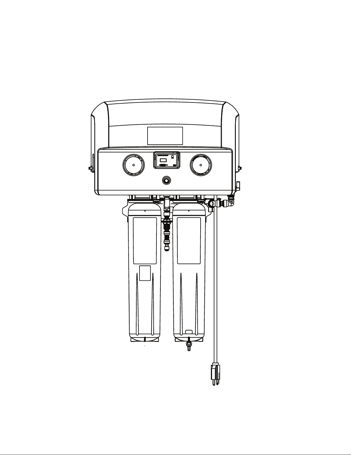
The ScaleGardTM HP reverse osmosis system is intended for use in filtering potable water and has not been evaluated for other
uses. The product is installed at the point of use and must be installed as specified in the installation instruction by a qualified
professional.
SAFETY INFORMATION
SAFETY INFORMATION
EXPLANATION OF SIGNAL WORD CONSEQUENCES
WARNING
WARNING
Indicates a potentially hazardous situation, which, if not avoided, could
result in death or serious injury and/or property damage.
CAUTION
CAUTION
Indicates a potentially hazardous situation which, if not avoided, may
result in minor or moderate injury and/or property damage.
NOTICE
NOTICE
Indicates a potentially hazardous situation, which, if not avoided, may
result in property damage.
CAUTION
CAUTION
To reduce the risks associated with environmental contamination which, if not avoided, could result in minor or moderate injury:
• At the end of useable life, dispose of this system in accordance with applicable local regulations or laws.
To reduce the risks associated with impact which, if not avoided, could result in minor or moderate injury:
• Depressurize system as shown in manual prior to cartridge removal.
To reduce the risks associated with heavy objects which, if not avoided, could result in minor or moderate injury:
• Follow safe lifting procedures.
WARNING
WARNING
Read entire manual. Failure to follow all guides and rules could cause personal injury or property damage.
• Check with your local public works department for plumbing codes. You must follow their guidelines as you install the water ltration system.
• Your water ltration system will withstand up to 125 pounds per square inch (psi) water pressure. If your water supply pressure is higher than 80 psi, install a
pressure reducing valve before installing the water ltration system.
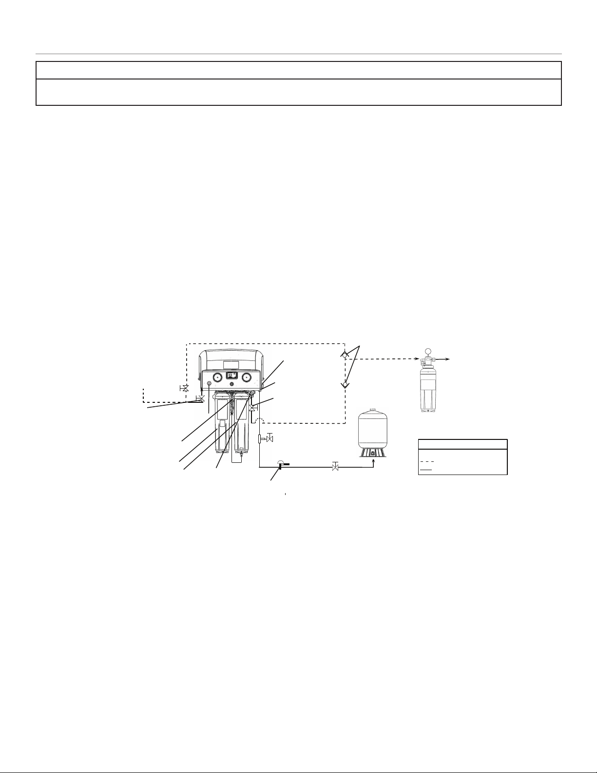
• An approved post lter and tank must be used with the RO system.
To reduce the risk associated with choking:
• DO NOT allow children under 3 years of age to have access to small parts during the installation of this product.
To reduce the risk associated with the ingestion of contaminants:
• DO NOT use with water that is microbiologically unsafe or of unknown quality without adequate disinfection before or after the system. Systems certied for
cyst reduction may be used on disinfected water that may contain lterable cysts.
To reduce the risk associated with hazardous voltage due to an installer drilling through existing electric wiring or water pipes in the area of
installation:
• DO NOT install near electric wiring or piping which may be in path of a drilling tool when selecting the position to mount the lter bracket.
To reduce the risk associated with back strain:
• Follow safe lifting procedures.
To reduce the risk of physical injury:
• All hydro-pneumatic pressurized tanks MUST have an appropriate pressure relief valve installed. Pressure relief valve must be maintained and inspected
every 6 months. Contact a plumbing professional if you are uncertain how to select/install/maintain a pressure relief valve.
To reduce the risk associated irritation from Sodium Metabisulte during installation:
• Sodium Metabisulte (CAS 007681-57-4) is used in a 1% preservative solution within the reverse osmosis membrane.
• DO NOT put this system into service before the RO tank is ushed as specied in the installation instructions. Wear eye and face protection during installation.
• To request an MSDS relating to this product call 203-238-8965 or visit the web at http://solutions.3m.com). For emergencies, call 800-364-3577 or 651-
737-6501 (24 hours).
To reduce the risk associated with ingestion of water contaminaed with sanitizer:
• After installation, sanitizer MUST be ushed from the system before rst use as directed within the installation instructions.
SAFETY INFORMATION CONTINUED ON NEXT PAGE
IF CONNECTION IS MADE TO A POTABLE WATER SYSTEM, THE SYSTEM SHALL BE PROTECTED AGAINST BACKFLOW.

4
NOTICE
NOTICE
To reduce the risk associated with property damage due to water leakage or ooding:
• Read and follow Use Instructions before installation and use of this system.
• Change the disposable lter cartridge at the recommended interval; the disposable pre-lter cartridge and post-lter cartridge MUST be
replaced every 24 months or sooner.
• Change the disposable membrane lter cartridge at the recommended interval; the disposable RO membrane cartridge MUST be replaced
every 24 months or sooner.
• Failure to replace the disposable lter and membrane cartridges at recommended intervals may lead to reduced lter performance and failure
of the lters, causing property damage from water leakage or ooding.
• Installation and use MUST comply with all state and local plumbing codes.
• Protect from freezing, remove lter cartridge when temperatures are expected to drop below 33° F (4.4° C).
• DO NOT install systems in areas where ambient temperatures may go above 110° F (43.3° C).
• DO NOT install on hot water supply lines. The maximum operating water temperature of this lter system is 100°F (37.8°C).
• DO NOT install if water pressure exceeds 125 psi (862 kPa). If your water pressure exceeds 80 psi (552 kPa), you must install a pressure
limiting valve. Contact a plumbing professional if you are uncertain how to check your water pressure.
• DO NOT install where water hammer conditions may occur. If water hammer conditions exist you must install a water hammer arrester.
Contact a plumbing professional if you are uncertain how to check for this condition.
• Where a backow prevention device is installed on a water system, a device for controlling pressure due to thermal expansion MUST be
installed. Contact a plumbing professional if you are uncertain how to select/install/maintain a thermal expansion device.
• Where a booster pump is installed on a water system, you MUST maintain and inspect the attached pressure switch regularly in accordance
with the booster pump manufacturer’s instructions. Contact a plumbing professional if you are uncertain how to maintain your booster pump
system.
• Where a booster pump is installed on a water system, you MUST install an appropriate pressure relief valve. Pressure relief valve must be
maintained and inspected every 6 months. Contact a plumbing professional if you are uncertain how select/install/maintain a pressure relief
valve.
• Where a booster pump is installed on a water system, you MUST install an appropriate pressure regulating valve and regulate water pressure
to <80psi. Contact a plumbing professional if you are uncertain how select/install/maintain a pressure regulating valve.
• DO NOT install in direct sunlight or outdoors.
• DO NOT install near water pipes which will be in path of a drilling tool when selecting the position to mount the bracket.
• Mount lter in such a position as to prevent it from being struck by other items used in the area of installation.
• Ensure that the location and fasteners will support the weight of the system when installed and full of water.
• Ensure all tubing and ttings are secure and free of leaks.
• DO NOT install unit if collet is missing. Contact 1-866-990-9785 if collets are missing from any ttings.
• Use compatible exible tubing with ‘push in connections’ (such as PEX tubing, PE tubing, PP tubing).
• DO NOT install with rigid piping (such as copper, aluminum, stainless steel, chrome plated, or anodized tubing).
• All hydro-pneumatic pressurized tanks MUST have an appropriate pressure relief valve installed. Pressure relief valve must be maintained
and inspected every 6 months. Contact a plumbing professional if you are uncertain how to select/install/maintain a pressure relief valve.
IMPORTANT NOTES
IMPORTANT NOTES
• Failure to follow instructions will void warranty.
• Allow a minimum of 3” (6.72 cm) clear space under lter to facilitate cartridge change.
• Install with the inlet and outlet ports as labeled. Make sure not to reverse connections.
• Some local codes may require the use of a licensed plumber or certied installer when disrupting a potable water line.
• This appliance can be used by children aged from 8 years and above and persons with reduced physical, sensory, or mental capabilities or lack of
experience and knowledge if they have been given supervision or instruction concerning use of the appliance in a safe way and understand the hazards
involved.
• Children shall not play with the appliance.
• Cleaning and user maintenance shall not be made by children without supervision.
• For cold water use only.

5
Parts List
The following parts comprise the ScaleGardTM HP Reverse Osmosis System. Please unpack the contents from the product box and check to verify
that all of the parts listed below are included. Should any parts be missing, please contact 3M Purication Inc. at 1-866-990-9785.
Description Quantity Part Number
ScaleGardTM HP Reverse Osmosis System 1 5629101 (110-120VAC with Pre-filter and RO)
6239301 (110-120VAC w/out Pre-filter and RO)
6239302 (220-240VAC w/out Pre-filter and RO)
6239303 (220-240VAC w/out Pre-filter and RO with UK plug)
6239304 (220-240VAC w/out Pre-filter and RO with AU plug)
HF90-CL-RO (Pre-Filter) 1 5613529
HFRO 500 (RO membrane) 1 5626903
Equipment Components Sold Separately
Description Quantity Part Number
Install Kit (Sold Separately) 1 6841441
SGHP Pre-Expansion Assembly Manifold 1 6235205
SGHP RO-Expansion Assembly Manifold 1 6232705
HFRO 700 (RO Membrane) 1 5626904
HFRO 33% Recovery Kit 1 50-93201
Required/Sold Separately
Description Quantity Part Number
BEV140/BEV160 Post Filter (Required/Sold Separately) 1 5616201/5616301
10 Gallon Pressure Tank (Required/Sold Separately) 1 5598407
20 Gallon Pressure Tank (Required/Sold Separately) 1 5598408
40 Gallon Pressure Tank (Required/Sold Separately) 1 5598409

6
Feedwater Requirements
IMPORTANT NOTES
IMPORTANT NOTES
• Be sure to confirm that the feedwater falls within the limits shown below. If unsure of the feedwater quality, check with your 3M™Water Filtration
Products distributor.
Inlet water pressure ............................30-125 psi (207-862 kPa)
Feed TDS .................................................. 1,000 ppm Maximum
Hardness...................................................<10 grains (171 mg/l)
Iron (Fe) ...................................................................... <0.1 mg/l
Hydrogen Sulde................................................... None Allowed
Feed pH ...............................................................................4-11
Free Chlorine............................................................... <0.1 mg/l
Manganese (Mn) .......................................................<0.05 mg/l
Turbidity..........................................................................<5 NTU
Temperature................................................................... >50 °F*
Challenge Water Recommendations
(
Contact dealer/distributor for assistance in water testing)
If there is iron or manganese above recomended limits present in the incoming-water, it is recommended to install water softening system upstream
of ScaleGard™HP System.
If incoming water hardness is greater than 10 grains (171 mg/l), it is recommended to install water softening system upstream and change the stan-
dard flow control on the drain-line to achieve recovery of the RO system at 33%. (HFRO 33% Recovery kit PN-50-93201)
If the particle count is >1000 counts/ml for particles less than 2 micron size or turbidity is greater than the recommended 5 ntu limit, then it may be
required to consider different prefiltration options and change the standard flow control on the drain-line to achieve recovery of the RO system at
33%. (HFRO 33% Recovery kit PN-50-93201) . Contact your dealer/distributor for details.
It is recommended to install an SGHP RO-EXP and SGHP Pre-EXP under the following conditions:
1. If more production capacity is needed.
2. If installed in a location where water temperature drops below 50 °F (10 °C) during any part of the year.
3. If the particle count is >1000 counts/ml for particles less than 2 micron size or turbidity is greater than 5 NTU limit.
4. If the incoming water TDS is greater than 1000ppm limit.
Other Requirements
Power.........110V (PN-5629101, 6239301), 220V (PN-6239302)
*If at any time during the year water temperature falls below 50 °F, see
challenge water recommendations below.
NOTICE
NOTICE
See safety information regarding reducing the risk associated with property damage due to water leakage or ooding on page 4 prior
to set-up and installation of the system.

7
Equipment Set-Up and Installation
Equipment Location
Prior to installing the ScaleGardTM HP Reverse Osmosis System, carefully plan the installation location for all system components.
Position the ScaleGard HP reverse osmosis base unit and the pressure tank in desired locations as per (Figure 1).
1. Access to feedwater, drain line connections and electrical outlet is required.
2. The ScaleGard HP System must be accessible and have at least 3 inches (7.62 cm) clearance on all sides of the system to facilitate servicing.
An additional 10" will be needed on both sides of the ScaleGard HP system to allow for the future installation of the SGHP Pre-EXP or the
SGHP RO-EXP manifolds.
3. The pressure tank should be installed within 15 ft (4.6 m) of the ScaleGard HP reverse osmosis base unit and 0.5” or larger tubing diameter is
required to complete installation.
Figure 1 — Plumbing Diagram
Bypass (Provided by Installer) Check Valve (Provided by Installer)
1/2” NPT Feed
Water Inlet
HF90-CL-RO (Pre-Filter)
HFRO 500 (RO Membrane)
3/8” JG Outlet to drain
Pre-Filter sample valve
Install kit shutoff valve
(Sold Separately)
Install kit shutoff valve
(Sold Separately)
1/2” JG Outlet to tank
1/2” NPT Outlet to Equipment
Install kit Tee Fitting and
sample valve (Sold Separately)
1/2” Tank shut off valve (Comes with Tank)
RO sample valve
BEV140/BEV160
Post Filter
(Required/Sold Separately)
To Equipment
Legend
Provided by Installer
Installation Kit (PN-6841441)
Pressure Tank
(Required/Sold Separately)
Pressure Relieve Valve
(Sold Separately)
NOTICE
NOTICE
See safety information regarding reducing the risk associated with property damage due to water leakage or ooding on page 4 prior
to set-up and installation of the system.

8
Wall Mounting the ScaleGardTM HP Base Unit
(Mounting Template included with unit)
1. Draw a level line on the wall where the bracket is to be mounted. Hold bracket key holes on level line and mark locations for screws.
2. Install mounting screws (not included) into each of the initial key holes as shown in gure 2. Be sure to leave 1/8” to 1/4” (0.3 to 0.6 cm) space
between the bottom of the screw head and the wall so that the bracket can be hung. (assume system weight of 57 lbs. (25.9 kg))
NOTICE
To reduce the risk associated with property damage due to water leakage or ooding:
• Mount ScaleGardTM HP base unit in such position as to prevent it from being struck by other items being used in the area
of installation. Ensure that the location and fasteners will support the weight of the system when installed.
IMPORTANT NOTES
• Allow a minimum of 3” (7.62 cm) clear space under lter to facilitate cartridge change.
3. Hang manifold from the mounting screws.
4. Once the bracket is hung, tighten the mounting screws so that the bracket is snug between the screw and the wall.
5. Install remaining mounting screws in locations as shown in gure 2.
MOUNTING HOLES
MOUNTING HOLES
MOUNTING HOLES
Figure 2 — Installing Mounting Screws
Operational weight - 57 lbs.

9
Plumbing Connections
1. Install feed water line to marked “Inlet” 1/2” NPT inlet connection.
2. Install RO water line from marked “Tank Outlet” to pressure tank (Sold Separately). Assemble and install pressure tank ttings per
instructions provided with tank.
3. Install RO water line from marked “Equipment Outlet” to the foodservice equipment. Installation of a post lter is required downstream of the
RO system (Required/Sold Separately).
4. Install drain line from marked “Drain Outlet” to the drain . An approved air gap must exist between the RO system reject drain line and the
drain opening to comply with state and local plumbing codes.
5. Install 1/2" Bypass line as shown on Figure 1-Plumbing Diagram (if required).
6. Check air pressure on the pressure tank using the valve on the tank. With the tank empty, the pressure should read between 7-18 psi (48-124
kPa). Adjust as required.
7. Plumbing connections for the ScaleGardTM HP reverse osmosis system are now complete.
Install cartridge per instructions below.
Pre-Filter and Post Filter Cartridge (blue label) Installation:
1. Remove red sanitary cap from new cartridge. Ensure o-rings are seated into their grooves and lubricate with water. Install with a quarter turn
to the right until cartridge come to a complete stop. NOTE: Cartridges are keyed to t in proper location only.
Figure 3 - Installation Instructions
Step 1: Remove the plug from the 1/4" tting at the bottom of the RO cartridge by pushing in the collet and pulling out the plug.
Step 2: Remove the Twin ow control assembly from the packaging.
Step 3: Firmly push the short tubing on one end of the twin ow control into the John Guest 1/4” NPT tting at bottom of the RO cartridge.
Step 4: Push the reject tubing into the tting in the twin ow control assembly.
Step 5: Operating pressure will need to be reset (See Operating Pressure Adjustment instructions on page 14).
HFRO 33% Recovery Kit HFRO 50% Recovery
(Use only if recommended by installer)

10
Start-Up Test Checklist
Close tank-valve, Open the “sample valve” (available downstream of RO)
• Pump turns on √
• Water visually ows through “sample valve” and drain line √
Keeping tank-valve closed, close the “sample valve”
• Pump turns off √
• Water stops owing through drain line √
• RO Feed Pressure” (Gauge 1) shows 0 psi (0 kPa, 0 bar) √
• “System Pressure” (Gauge 2) shows about 60 psi (414 kPa, 4.14 bar) for 110-120VAC systems and 70 psi (483 kPa, 4.83 bar) for 22-240VAC
systems √
Open the “sample valve”
• Pump on and “RO Feed Pressure” (Gauge 1) shows 110-125 psi (758-862 kPa, 7.58-8.62 bar) √
• “System Pressure” (Gauge 2) shows 0 psi (0 kPa, 0 bar) √
• Permeate being rinsed for rst 25 seconds √
• After 30 seconds of ow, check if measured production rate is as expected √
• After 30 seconds of ow, check if TDS reduction is as expected √
Close the “sample valve” and allow the tank to fill up
• Verify “System Pressure” (Gauge 2) increases slowly to 60 psi (414 kPa, 4.14 bar) for 110-120VAC systems and 70 psi (483 kPa, 4.83 bar) for
220-240VAC systems as tank lls up √
• Verify pump turns off and reject-ow shuts off when “System Pressure” (Gauge 2) is 60 psi (414 kPa, 4.14 bar) √
System Start Up
1. Open unit inlet shutoff valve (See Figure 1, page 7)
2. Turn ON the feedwater supply by plugging system into electrical outlet.
3. Open Pre-Filter ush valve to vent air from system and ush for
10 gallons (approximately 5 minutes). If error light turns ON during
Pre-Filter ushing process then press reset button.
4. Close ush valve. Pre-Filter pressure gauge (left gauge) should read between
115-125 psi.(See Operating Pressure instructions to adjust)
5. Complete blending valve adjustment procedure below. (See instructions below)
6. Allow tank to ll until the RO unit turns OFF on full tank (See chart). Tank operating pressure
for the 110-120VAC version is ON at 40 psi (276 kPa, 2.76 bar) and OFF at 60 psi (414 kPa, 4.14
bar) (right gauge). Tank operating pressure for the 220-240VAC is ON at 50 psi (345 kPa, 3.45
bar) and OFF at 70 psi (483 kPa, 4.83 bar).
7. Flush membrane by opening pressure tank sample valve and empty tank to drain. After ushing
the system for at least 24 hours, close the tank sample valve.
8. Sanitize the Storage Tank and RO System according to the storage tank and RO system
sanitizing instructions on page 11.
9. Allow tank to ll again. System is now ready for use.
Part Number Pressure Volume Approximate
Time to Fill
5598407 10 gallons (38 liters) 0.3 hours
5598408 20 gallons (76 liters) 0.6 hours
5598409 40 gallons (151 liters) 1.2 hours
Required (Sold Separately)
Figure 4 (Reset Button)

11
Blending Valve Adjustment Instructions:
IMPORTANT NOTES:
• Typical TDS (Total Dissolved Solids) values for coffee are 80-200 ppm (parts per million) and occasionally lower for espresso, depending
upon taste preference. Typical TDS valves for steam and combi ovens are less than 50ppm.
•The blending valve should be set at start-up and checked periodically, for example when changing filter cartridges. The valve is a
precision metering valve, that may be locked by tightening lock nut.
•To set blending valve use TDS monitor set in the "out" position.
1. Open shut off valve in blending line.
2. Allow unit to run and ll tank for 5 min.
3. To adjust blending, rotate the blending valve to the left (counterclockwise) to increase the product water TDS and to the right (clockwise) to
decrease the product water TDS (See Figure 5 item #2 below). The valve should be opened intermittently a quarter turn at a time. Check the
TDS after each incremental adjustment and again two (2) minutes after the desired TDS value is reached. Re-adjust and check, as needed.
(See Figure 5-item #2 below)
4. Lock the blending valve using the lock nut.
5. After TDS is set, drain RO tank. System is now ready for use.
IMPORTANT NOTE: The TDS Monitor is push-button operated and requires two (2) 357A batteries. (Included in TDS meter)
Membrane Flushing Instructions:
1. Open pressure tank sample valve and empty tank to drain.
2. Flush system for at least 24 hours.
3. Close tank sample valve
Storage Tank and RO System Sanitizing Instructions:
Sanitizing the storage tank requires:
• Common household bleach (5.25% non-scented) or sanitizing agent
• Eye dropper or plastic oral syringe
a.) Disconnect the 1/2” line from marked”Tank Outlet” to pressure tank.
b.) Insert 15ml (0.5 ounces) of bleach or sanitizing agent into 1/2” line to pressure tank.
c.) Reconnect the 1/2” line to pressure tank.
d.) Turn ON the feedwater supply by plugging system into electrical outlet.
e.) Wait 4-5 hours.
f.) Open pressure tank sample valve and empty tank to drain.
g.) Sanitizing is now complete.
h) If there is any residual chlorine/bleach taste in the next tank full, drain tank completely a second time.
21
Reset
Button
Figure 5

12
C1
X1
X2
X3
X4
C2
X5
X6
C4
Y4
X7
X8
C3
Y1
Y2
Y5
Y6
C1
NC1
NO1
C2
NC2
NO2
C3
NC3
NO3
C4
NC4
NO4
PLC
(FRONT)
OUTPUT
MODULE
24v
+
-
GND
123
4
BLK
WHT
COM
AC SOURCE
1 PHASE
M
1/3 HP
1 phase
Flow Switch
.07gpm off
Pressure Switch
60psi on - 40 psi off
Solenoid Valve
Permeate
Dump
Solenoid Valve
Inlet Flow
Reset
Button
Step Down
Transformer
Warning Light
GND
BLK
COM
WHT
BLK
WHT
COM
BLK
WHT
COM
24v
110 - 240 VAC
Y3
PLC
(BOTTOM)
GND
GND
Figure 6 — Unit Flow Chart
Figure 7 — Electrical Diagram 110V Figure 8 — Electrical Diagram 220V
C1
X1
X2
X3
X4
C2
X5
X6
C4
Y4
X7
X8
C3
Y1
Y2
Y5
Y6
12 12
11
14
A1
A2
PLC(FRONT)
12
BROWN
BLUE
AC SOURCE
1 PHASE
M
1/3 HP
1 phase
Solenoid
Valve
Permeate
Dump
Solenoid
Valve Inlet
Flow
Pump Motor
Reset Button
Warning Light
GND
BROWN
BLUE
Y3
PLC
(BOTTOM)
GND
24v
GND
-
RELAY
GND
220 -
240 VAC
24v
WHT
Center
BLK/BARE
BLUE
BROWN
Step Down
Transformer
3
WIRE
NUT
8
LEVER NUT
14
11
6
LEVER
NUT
5
LEVER
NUT
7
LEVER NUT
TERMINAL BLOCK
+
Output LED Color Meaning Normal Running Condition
PWR Green On when the units power cord is plugged in ON
RUN Green On if PLC is powered with switch in run position ON
ERR Green On when PLC is not functioning properly OFF
X1 Green On when the pressure-switch is closed telling PLC to make water ON
X2 Green On when the ow-switch is closed signaling good ow ON
X3 Green On when the reset button is being pressed down OFF
Y1 Red On when the Inlet solenoid is being signaled by PLC to open (make RO-water) ON
Y2 Red On when the permeate rinse solenoid is being signaled by PLC to open (rinse) On for 25 seconds then OFF
Y3 Red On when The service indicator light is being signaled by PLC to turn on OFF
NO1 (110-120VAC) Red On when the motor/pump is being signaled by PLC to turn on (make RO water) ON
Y5 (220-240VAC) Red
Advanced Diagnosis for Certied Technicians ONLY
Caution/Warning: High Voltage in the Control Box

13
B. If Tank Switch is < 40 psi
1. Inlet solenoid valve and permeate rinse solenoid open
2. 2 second delay, motor / pump start
3. 25 second delay permeate rinse solenoid closes
4. Monitoring of the ow switch starts
a. If ow switch is closed (ow detected) unit continues to operate lling the tank
1. Tank switch senses pressure > 60 psi (414 kPa, 4.14 bar) for 110-120VAC systems or 70 psi (483 kPa, 4.83 bar) for 220-
240VAC systems
2. Motor / pump shut down
3. 5 second delay inlet solenoid valve shuts off
4. Unit is shut down on full tank.
5. When pressure in tanks fall below 40 psi (276 kPa, 2.76 bar) for 110-120VAC systems or 50 psi (345 kPa, 3.45 bar) for 220-
240VAC systems,return to B.1
b. If ow switch is open (no ow detected)
1. No ow signal is ignored for 15 seconds and the “TOGGLE CYCLE” starts
ScaleGard™ HP PLC (Programable Logic Controller) Program Version 9.8 Sequence of Operation
Plug unit in, both the Power and Run LED’s are Green
A. If Tank Switch is > 60 psi (414 kPa, 4.14 bar) for 110-120VAC systems or 70 psi (483 kPa, 4.83 bar) for 220-240VAC systems, the unit
is off on full tank
1. Unit will cycle on when tank switch senses < 40 psi
“TOGGLE CYCLE”
1. Motor / Pump stop
2. 2 second delay the inlet solenoid closes
3. 1 second delay the inlet solenoid opens
4. 1 second delay the motor / pump start
5. 12 second delay check ow for three consecutive readings at 2 second intervals
Note: The “TOGGLE CYCLE” can/will repeat 4 times.
1. RETURN to NORMAL OPERATION If the ow switch closes (sensing ow) for 3 consecutive
readings during any of the “toggle cycles”, the unit will return to normal operation (B.1)
2. TOGGLE SHUT DOWN If the ow switch closes (sensing ow) at any time during the toggle cycle the
unit will go into the TOGGLE SHUT DOWN mode
“TOGGLE SHUT DOWN”
1. Motor / pump shut down
2. 5 second delay the inlet solenoid valve closes
3. ERROR light blinking
4. After 10 minutes the unit returns to operation (B.1)
The unit will count the number of toggle shut downs.
If the unit shuts down in the 10 minute toggle mode 10 times the shut down time is increased to 60 minute shut down.
The unit will shut down in the 60 minute shut down mode 1 time and the shut down mode will return to the
10 minute mode with the counter reset and counting to 10 again.

14
Lock Nut/set screw
Operating Pressure
Gauge
Pressure Relief Valve Pre-Filter
Blend Valve Line
Shroud
Bypass Plug (PN-6217402)
Operating Pressure Adjustment Instructions
1. Turn off / unplug the ScaleGard™HP Reverse Osmosis Unit.
2. Remove the shroud from the unit. (See diagram)
3. Open the pressure relief valve on the left side of the manifold to relieve the water pressure in the manifold (See diagram). If the water
continues to ow out of the pressure relief valve, the inlet water solenoid needs to be serviced. Right gauge (tank gauge) will not lose pressure.
4. Remove the prelter cartridge from the left cartridge head on the manifold. (See diagram)
5. Install bypass plug (3M part # 6217402) into the left hand cartridge head on the manifold. (Note: Operating pressure can't be set/adjusted with
used pre-lter cartridges)
6. Close the pressure relief valve.
7. Close the shut off valve in the blend valve line (see diagram).
8. Remove the pressure adjustment lock nut on the water pump to access the set screw (see diagram).
9. Turn on / plug in the SGHP RO unit.
10. Reading the left hand gauge on the unit, use the set screw to adjust the operating pressure to 115 psi +/- 5 psi and not to exceed 120 psi.
11. Turn the set screw in to increase the pressure, out to decrease the pressure. Note: A small amount of water may leak around the set screw,
this is normal.
To reduce the risk associated with property damage due to water leakage or ooding:
Notice: Take care when using pliers or pipe wrenches to tighten plastic ttings, as damage may occur if over tightening occurs.
12. When the operating pressure is set, replace the lock nut and recheck the operating pressure, readjust if necessary. (Do not over tighten lock
nut). Check for water leaks, repair as necessary.
13. Turn off / unplug the SGHP RO unit.
14. Open the pressure relief valve on the left side of the manifold to relieve the manifold water pressure.
15. Remove the bypass plug and reinstall the pre lter cartridge.
16. Close the pressure relief valve.
17. Open the blend valve line shut off valve.
18. Replace the shroud on the unit.
19. Turn on / plug in the SGHP RO unit Note: if the operating pressure is lower than the adjusted pressure, DO NOT READJUST. The reduced
pressure is due to a restriction in the prelter cartridge. It is recommended to change the prelter cartridge.
Important: If pressure drops below 80 psi with prelter installed, Pre-Filter MUST be replaced.
3. ERROR SHUT DOWN If the ow switch stays open (no ow) after the 4th repeat the unit will shut down in “ERROR SHUT DOWN”.
1. The motor / pump shut down
2. 5 second delay inlet solenoid valve closes
3. ERROR light on solid red.
4. Unit will have to manually be restarted.
The unit can/will be reset back to normal operation during the toggle mode by:
1. Unplugging the unit or pressing the reset button on the top of the PLC box
2. Unit cycles off on full tank

15
Shut-Off procedure:
RO membrane cartridge will need to be changed at least every twenty four (24) months. Pre and Post Filter cartridges must be replaced every six
(6) months.
1. Unplug system from the wall outlet, which will shutoff feedwater to RO system.
2. Open Pre-lter sample valve until ow stops and left pressure gauge reaches 0 psi to relieve pressure.
Pre-Filter and Post Filter Cartridge (blue label) Replacement:
1. Push and hold yellow tab to release cartridge locking mechanism while simultaneously rotating cartridge to the left.
2. Using both hands and holding the cartridge from the bottom, rotate the cartridge a quarter turn to the left and gently pull down.
NOTE: A small amount of water will drain from manifold as cartridge is removed.
3. Remove red sanitary cap from new cartridge. Ensure o-rings are seated into their grooves and lubricate with water. Install with a quarter turn to
the right until cartridge come to a complete stop. NOTE: Cartridges are keyed to t in proper location only.
RO Membrane Cartridge (green label) Replacement:
1. Remove the reject tubing and the elbow from the RO membrane cartridge. (See Figure 1).
2. Push and hold yellow tab to release RO membrane cartridge locking mechanism while simultaneously rotating RO membrane cartridge to the
left.
3. Using both hands and holding the RO membrane cartridge from the bottom, rotate the RO membrane cartridge a quarter turn to the left and
gently pull down. NOTE: A small amount of water will drain from manifold as cartridge is removed.
Routine Maintenance Cartridge Change-out Instructions (Pre/ Post Filter and RO Membrane Cartridge)
WARNING
WARNING
Read entire manual. Failure to follow all guide and rules could cause personal injury or property damage.
• Check with your local public works department for plumbing codes. You must follow their guidelines as you install the water filtration system.
• Your water filtration system will withstand up to 125 pounds per square inch (psi) water pressure. If your water supply pressure is higher than
80 psi, install a pressure reducing valve before installing the water filtration system.
To reduce the risk associated with choking:
• DO NOT allow children under 3 years of age to have access to small parts during the installation of this product.
To reduce the risk associated with the ingestion of contaminants:
• DO NOT use with water that is microbiologicaly unsafe or of unknown quality without adequate disinfection before or after the system. Systems certified
for cyst reduction may be used on disinfected water that may contain filterable cysts.
NOTICE
NOTICE
To reduce the risk associated with property damage due to water leakage or flooding:
• Read and follow Use Instructions provided with the original system prior to use of this replacement cartridge.
• Change the disposable filter cartridge at the recommended interval; the disposable filter cartridge MUST be replaced every 24 months or sooner.
• Failure to replace the disposable filter cartridge at recommended intervals may lead to reduced filter performance and failure of the filter, causing
property damage from water leakage or flooding.
• Protect from freezing, remove filter cartridge when temperatures are expected to drop below 33° F (4.4° C).
• DO NOT install systems in areas where ambient temperatures may go above 110° F (43.3° C).
• DO NOT install on hot water supply lines. The maximum operating water temperature of this filter system is 100°F (37.8°C).
• DO NOT install if water pressure exceeds 125 psi (862 kPa). If your water pressure exceeds 80 psi (552 kPa), you must install a pressure limiting valve.
Contact a plumbing professional if you are uncertain how to check your water pressure.
IMPORTANT NOTE:
The RO membrane cartridges have green labels and will only t into the head on the right side of the manifold (head has a green 3M label).

16
Routine Maintenance Cartridge Change-out Instructions (Pre-Filter and RO Membrane Cartridge)
To Attach Tubing To Release Tubing
Push tubing straight in as far as it
will go
Tubing is secured in. Push in collet to release tubing. Pull tubing straight out.
This product is outtted with a user friendly ‘Push In’ connector at the vent valve. Proper use of the connectors is shown in the gure below.
It is most important that the tubing selected for use with these connectors be of high quality, exact size and roundness, and with no surface
nicks or scratches. If it is necessary to cut the tubing, use a plastic tubing cutter or sharp razor knife. Make a clean square cut. Should a
leak occur at a “Push-In” connector, the cause is usually a problem with the tubing.
To Fix:
1. Relieve pressure 2. Release tubing 3. Cut off at least 1/4” from end
4. Reattach tubing 5. Conrm connection is leak free
Figure 9 (How to Use “Push-in” Connectors)
4. Remove sanitary cap from new RO membrane cartridge. Ensure o-rings are seated into their grooves and lubricate with water. Remove plug
from new RO membrane cartridge. Install with a quarter turn to the right until RO membrane cartridge comes to a complete stop.
NOTE: RO membrane cartridges are keyed to t in proper location only.
5. Remove the old ow control from the elbow and discard. Install the new ow control, included with the new RO membrane cartridge, in the
elbow (See Figure 2)
6. Connect reject tubing with elbow to RO membrane cartridge.
7. Flush membrane by opening pressure tank sample valve and empty tank to drain. After ushing the system for at least 24 hours, close the
tank sample valve.
System Start Up
Refer to System Start Up procedure (See page 10)
RO Membrane Cartridge (green label) Replacement Cont.:

17
Troubleshooting Guide
Problem Possible Cause Solution Notes
Unit Runs Low or Out of Water
Undersized tank for store demand Install additional storage tank capacity Contact Dealer
RO production is to low for store
demand
Install RO add-on head and cartridge
Contact Dealer
Upgrade from HFRO 500 to HFRO 700
Cartridge
Slow leak in the distribution line Repair leak The unit produced RO water slowly. A dripping leak
can prevent the tank from filling.
RO membrane flow control
improperly installed or missing Properly install RO membrane flow control Note: Reference RO cartridge change-out
instructions
System shuts down and "service"
indicator light turns on blinking
Pre-Filter plugs left hand gauge
reads less than 90
Replace Pre-Filter
—
Wait for 10-60 minutes to see if system
restarts
Low production rate
Replace RO membrane
RO membrane fouls, low
production
System shuts down and “service”
indicator light turns on solid
Pre-Filter plugs left hand gauge
reads less than 90 Replace Pre-Filter
A more frequent schedule change-out
may be needed (Refer to Challenge Water
Recommendations on page 6)
RO membrane fouls (normal
conditions)
Replace RO membrane Check for: 1. feedwater pressure, 2. production
flow rate, 3. drain flow rate before replacing RO
membrane
Ensure drain line is not kinked or plugged.
Replace if needed.
RO membrane fouls (high feed
water hardness/TDS)
Install RO add-on head and cartridge
Contact Dealer
Install a HFRO 33% Recovery Kit
Install water softener upstream
RO membrane fouls (high particle
load in incoming water)
Install prefilter and RO expansion heads and
cartridges
Interrupted feedwater supply Press Reset button on top of electrical
enclosure Reference system startup procedure
Water temperature below 50 °F Install RO expansion head and cartridge
Low feedwater pressure (below
30 psi) Contact plumber to resolve problem Reference system startup procedure once low feed
water problem is resolved
Iron or Manganese in incoming
water
Contact your dealer/distributor to install
specific iron or manganese reduction system
TDS of product water too low Blend too low Re-adjust blending valve to allow more
blending Reference Blending Valve Adjustment
TDS of product water too high Blend to high Re-adjust blending valve to allow less blending Reference Blending Valve Adjustment
TDS of product water too high with
no blending
RO membrane needs to be
replaced Replace RO membranes —
TDS monitor not operating Low battery Replace TDS monitor batteries —
Technical Support - 1-866-990-9785

18
Replacement Parts
Part Number Description
96-410501 Pressure Reducer/Regulator (Contact Dealer)
60-9052 Inlet ball valve (Contact Dealer)
22-518801 Pre-programmed PLC for 5629101 and 6239301 (Contact Dealer)
25-212401 Relay Output Module for 5629101 and 6239301
22-518802 Pre-programmed PLC for 6239302, 629303, 6239304 (Contact Dealer)
22-115401 Relay Output Module for 6239302, 6239303, and 6239304
8500557 Pressure Gauge (Contact Dealer)
60-125001 Permeate Solenoid (Contact Dealer)
85-9274 Shroud (Contact Dealer)
89-3220101 Pump Head (Contact Dealer)
89-2302 Pump Motor (Contact Dealer)
5613529 HF90-CL-RO Pre-Filter
5626903 HFRO 500 Cartridge
5626904 HFRO 700 Cartridge
50-93201 HFRO 33% Recovery Kit
6232631 TDS Monitor
24-500101 Flow Switch
25-15501 Pressure Switch (40/60 psi)
25-15500 Pressure Switch (50/70 psi)
60-103601 Inlet Solenoid (Contact Dealer)
6217402 Bypass Plug
5613303 Post Filter HF40 Replacement Cartridge for BEV140 (Required/Sold Separately)
5613403 Post Filter HF60 Replacement Cartridge for BEV160 (Required/Sold Separately)

19
Notes

3M and ScaleGard are trademarks of 3M Company.
© 2017 3M Company. All rights reserved.
Please recycle. Printed in U.S.A.
34-8720-4690-8
3M Purication Inc.
400 Research Parkway
Meriden, CT 06450, U.S.A.
Tel (866) 990-9785
(203) 237-5541
Fax (203) 238-8701
www.3MFoodservice
www.3Mpurication.com
Product Use:
Many factors beyond 3M Purication Inc.'s (3M’s) control and uniquely within user’s knowledge and control can affect the use and performance
of a 3M product in a particular application. User is solely responsible for evaluating the 3M product and determining whether it is t for a
particular purpose and suitable for user’s method of application.
Warranty, Limited Remedy, and Disclaimer:
3M warrants that this product (excluding lter cartridge or lter membrane) will be free from defects in material and manufacture for the period
of (1) year from the date of purchase. The lter cartridge or membrane is warranted to be free from defects in material and manufacture for
one (1) year. No warranty is given as to the service life of any lter cartridge or membrane as it will vary with local water conditions and water
consumption. 3M MAKES NO OTHER WARRANTIES OR CONDITIONS, EXPRESS OR IMPLIED, INCLUDING, BUT NOT LIMITED TO, ANY
IMPLIED WARRANTY OR CONDITION OF MERCHANTABILITY OR FITNESS FOR A PARTICULAR PURPOSE OR ANY IMPLIED WARRANTY OR
CONDITION ARISING OUT OF A COURSE OF DEALING, CUSTOM OR USAGE OF TRADE.
If the 3M product does not conform to this warranty, then the sole and exclusive remedy is, at 3M’s option, replacement of the 3M product or
refund of the purchase price.
Limitation of Liability:
Except where prohibited by law, 3M will not be liable for any loss or damage arising from the 3M product, whether direct, indirect, special,
incidental or consequential, regardless of the legal theory asserted, including warranty, contract, negligence or strict liability.
Other manuals for ScaleGard HP
1
This manual suits for next models
5
Table of contents
Other 3M Water Filtration System manuals
Popular Water Filtration System manuals by other brands

EcoWater
EcoWater ECWF8 manual

Vixen Air
Vixen Air VXF3938SR installation guide

Hydro International
Hydro International Hydro-Sludge Screen manual

Eljen
Eljen Mantis M5 Series Installation and System Design Guide

Neptun
Neptun Classic NCTF-O 8000 operating instructions

Microlene
Microlene UV24 Installation and operating instructions

Premier
Premier WP-4V Installation, operation and maintenance manual

LaserLiner
LaserLiner AirBreeze 120 manual

Omnifilter
Omnifilter US2000 installation instructions

Dryfast
Dryfast FB300 instruction manual

Hommix
Hommix puRO GWP-43C6500M user manual

Wilkerson
Wilkerson SF1 Installation & service instructions