biodex 846 User manual

FN: 06-158 Rev A 8/14
BIODEX
Biodex Medical Systems, Inc.
SURGICAL C-ARM TABLE - 846
INSTALLATION/ OPERATION MANUAL
058-846
058-847

!./72'39'1)4:+67/378'11'8/43'3*45+6'8/43564)+*96+7,468.+,4114;/3-564*9)87
#058-846 Table, Surgical C-Arm - 846, 115 VAC
#058-847 Table, Surgical C-Arm - 847, 230 VAC
SURGICAL C-ARM TABLE - 846
Symbol Meaning
CAUTION: efertoinstructionmanualbeforeoperatingorservicingsystem.
ATTENTION:Seréféreràlanoticed'utilisationavantd'utiliserl'equipement.
CAUTION:Disconnectpowerfromsourcebeforeremovingpanelorcovers. eliablegrounding
achievedonlybyconnectingthisunittoanequivalentmarkedhospitalonlyorhospitalreceptacle.
ATTENTION:Déconnectorlaprisesecteuravantd'ouvrirlecoffret.Uneterrefiablenepeutétre
obtenuequeparlaconnexionàuneprisesecteurdequalitéhospitalière.

!"!
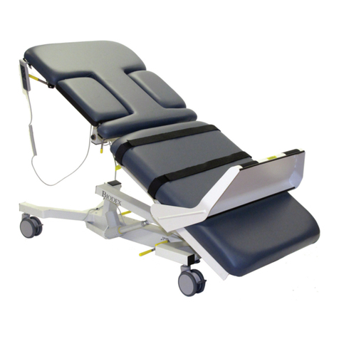
The Surgical C-Arm Table – 846 features an economical, no-
nonsense float top design that allows for quick and comfort-
able patient positioning. Its large radiolucent area, motorized
actuation of height and free-float X-Y tabletop make it ideal
for both pain care and cardiovascular applications. The
tabletop’s innovative contour combines the advantages of
square and contoured tabletops, offering additional space at
the head-end of the table while enabling the user to get the
C-Arm close to the cervical spine for greater image resolution.
Designed for procedures where stability, access and precise,
quiet, vibration-free positioning are essential, this table’s
functional design allows complete access with reduced radi-
ation exposure to clinicians. Patient comfort and stability are
assured by two-inch thick table padding and three adjustable
straps with Velcro®hook and loop fastening. A face cutout is
provided for prone positioning.
NOTE: The058-846and058-847tabletopismadeofcar-
bonfiber.Thismaterial,asusedinthisproduct,iscertified
tomeetalltherequirementsofradiationperformancestan-
dardsof21CF SubchapterJ.
Figure1-Partsandadjustmentmechanisms.
1. Hand-HeldController
2. Free-FloatX-YTabletop eleaseButton
3. FootEndLockingBrakesandSwivelCasters
4. FrontEndCasterBrakeLockingBar
! !"!
CAUTION: efertoinstructionmanualbefore
operatingorservicingsystem.
ATTENTION: Seréféreràlanoticed’utilisation
avantd’utiliserl’equipement.
CAUTION: Hospitalgradeplugtobepluggedinto
ahospitalgradereceptacleonlytoachieve
groundingreliability.
ATTENTION: Lafichedequalitéhúpitalnedoit
ÍtrebranchÈequesuruneprisedecourantde
qualitéhÙpital,pourunemiseálaterrefiable.
CAUTION: Beforetransferringapatientontooroff
thetable,ensureallfourcasterbrakesarelocked.
Securetherestrainingstrapsimmediatelyafter
positioningthepatientonthetable.
ATTENTION: Avantletransfertdupatientsurla
tableouhorsdelatable,síassurerquelesquatre
freinsdesroulettessontbloqués.Fixerles
lanièresdíimmobilisationdèsquíonapositionnéle
patientsurlatable.
CAUTION: Therestrainingstrapsarenotintended
torestrainanuncontrolledpatient.
ATTENTION: Leslaniéresdíimmobilisationníont
paspourobjetlíimmobilisationdíunpatienthors
decontrúle.
!
!
!
!
!
!
!
!

!.+4)0/3-6'0+7'3* ;/:+1'78+67
(SeeFigure2.)
The locking brakes and swivel casters allow this table to
glide effortlessly on hard surfaces and across firm rugs.
The foot end casters are locked from either side of the
table while the head end casters are locked together using
the Caster Brake ocking Bar.
1. To release the lock on the brakes and swivel casters at the
foot end of the table, use your toe to lift up on the Foot End
Caster Brake ocking ever on either side of the table.
2. To lock the foot end brakes and swivel casters, step
down on the Foot End Caster Brake ocking ever on
either side of the table.
3. To lock the brakes and swivel casters for the head end
of the table, use your toe to press down on the Head
End Caster Brake ocking Bar.
4. To release the head end brake and swivel casters, use your
toe to lift up on the Head End Caster Brake ocking bar.
NOTE: TheHeadEndCasterBrakeLockingBar,when
presseddowninthelockposition,raisestheheadend
castersslightlyofftheground.Theamountthatcastersare
raisedcanbeadjustedbysimplyusinga5/8"open-end
wrenchtoadjustupordownthesupportfootlocatedunder
theheadendcasterbrakelockingbar.
Figure2.FootEndCasterBrakeLockingLeverandcasters.
Figure3.HeadEndCasterBrakeLockingBar.
"7/3-8.+'3*+1*4386411+6
The Hand-Held Controller may be used to adjust table
height and X-Y positioning. When not in use, the Hand-
Held Controller can be hooked onto the accessory rail.
CAUTION: Beforemovingthetabletop,besure
thatallI.V.lines,attachmentsandrestraining
straps,etc.,areoutoftheway.Ensurethepatient
isfullysecuredtothetabletopbytherestraining
straps.
ATTENTION: Avanttoutdéplacementdudossier,
veilleráendégagerleslignesdegoutte-á-goutte
intravéneux,lesaccessoires,leslaniéresdíimmo-
bilisation,etc.Síassurerquelepatientestsolide-
mentfixéaudossierálíaidedeslaniéresdíimmo-
bilisation.
To adjust the table position, press and hold the appropriate
switch on the Hand-Held Controller. The tabletop will move
in the direction indicated by the switch. Release the switch
when the tabletop achieves the desired position.
NOTE: Thetablecanperformonlyonemotorizedfunction
atatime.IfyoupressasecondbuttonontheHand-Held
Controllerwhilethetableisalreadyperformingamotorized
functionthetabletopmovementwillstop.Atthatpoint,you
willneedtoreleaseallbuttonsbeforeyoucanresumethe
selectedfunction.
NOTA: Latablenepeutexécuterquíunseuldéplacement
motoriséálafois.Lefaitdíappuyersurunsecondbouton
delacommandeámainencoursdedéplacementdelíap-
pareilprovoquelíarrÍtdumouvementdudossier.Ilfaut
alorsrel‚chertouslesboutonsavantdereprendrelafonc-
tionchoisie.
'78+66'0+
4)0/3-+:+6
!
!

47/8/43/3-!.+%&6++14'8!'(1+845
(SeeFigure4.)
The X-Y free-float tabletop is positioned using the red
Tabletop Handgrip. The red handgrip has a push button
that, when depressed, allows the table to move in both the
X and Y planes. To move the tabletop, depress the push
button on the red handgrip and slide the tabletop to the
desired position. Release the button to lock the tabletop in
place.
The Tabletop Handgrip may be positioned at any point
along the accessory rail. You can position the grip in either
a horizontal or vertical plane. To position the grip, loosen
the handgrip locking knob, slide the grip to the desired
position along the accessory rail, then tighten the locking
knob to secure the grip.
Figure4.Pushbutton(onredhandle)releasestabletopfor
free-floatX-Ymotion.
'8.+8+6!6'=<8+37/4358/43'1
(SeeFigure5.)
The removable Catheter Tray Extension can be used to
provide additional table length for accommodation of
catheters within the patient’s sterile field. This makes the
procedure easier, safer and reduces the risk of breaking
the sterility of the catheters.
CAUTION: TheCatheterExtensionisnot
radiolucentandnotsuitableforpatientsupport.
ATTENTION: LéxtensionduCathéternéstpas
radiotransparentetnepasconvenablepor
supporteanpatient.
To attach the Catheter Tray Extension, simply hook the
extension guides over the accessory rails at the foot end of
the table and lower the extension into position.
Figure5.CatheterTrayExtension.
#41+58/43'1
The adjustable height I.V. Pole should be installed onto the
O.R. accessory rail. oosen the I.V. Pole locking knob at
the base of the slide block and slide the block and pole
onto the accessory rail until it is in the desired position.
Tighten the locking knob to secure the pole.
To adjust the height of the I.V. Pole, loosen the height
adjustment locking knob and raise or lower the top section
of the pole to the appropriate height. Tighten the locking
knob to secure.
!
!

SAFETY GUIDELINES
1.Securerestrainingstrapsimmediatelyafter
placingthepatientonthetable.Therestraining
strapspreventthepatientfromrollingofftheside
ofthetable.
NOTE: Therestrainingstrapsarenotintendedto
restrainanuncontrolledpatient.
2.Alwayslockthecastersbeforemovingapatient
ontooroffthetable.
3.Thistableisratedtosupportpatientsweighing
uptoamaximumof500pounds.
CONSIGNES DE SECUrITE
1.Fixerleslaniëresdíimmobilisationetleslaniëres
dechevilleimmédiatementaprësavoirplacéle
patientsurlatable.Leslaniëresdecheville
empÍchentlepatientdeglissersouslatableen
positiondeTrendelenburg.Leslaniëresdíimmobili
sationempÍchentlepatientderoulerpar-dessusle
cútédelatable.
NOTA: Leslaniëresdíimmobilisationníontpas
pourobjetlíimmobilisationdíunpatienthorsde
contrúle.
2.Toujoursbloquerlesroulettesavantdefaire
monterlepatientsurlatableoudelíenfaire
descendre.
3.Latableestcertifiéecommepouvantsupporter
unpatientpesantauplus227kg(500lb).
!
The Biodex Surgical C-Arm Table - 846 is virtually mainte-
nance free. By following the instructions below at suggest-
ed time intervals, or as often as necessary, your table will
remain in “like new” condition.
1. As required, clean all exterior painted surfaces, tabletop
and restraining straps with a mild detergent solution.
2. Wheels and wheel locks should remain free of foreign
materials and dirt accumulation. Keeping wheel assemblies
free of this matter will ensure smooth table transportation
and free lock/unlock wheel operation.
CAUTION: Disconnectpowerfromsourcebefore
removingpanelorcovers. eliablegroundingachieved
onlybyconnectingthisunittoanequivalentmarked
hospitalonlyorhospitalgradereceptacle.
ATTENTION: Déconnectorlaprisesecteuravant
d’ouvrirlecoffret.Uneterrefiablenepeutétre
obtenuequeparlaconnexionàuneprisesecteur
dequalitéhospitalière.
!
/2+37/437 104" l x 26" w (260 x 66 cm) with
OR accessory rails
!'(1+845 101" l x 24" w (252 x 61 cm)
'*/419)+386+'
51" l x 24" w (128 x 61 cm) unobstructed head to
accessory rail
20" l x 17.5" w (50.8 x 44 cm) additional, between
accessory rails
'*/419)+386+'!48'1+3-8. 71" l (178 cm)
!'(1+845'8+6/'1 Carbon Fiber with integral head section
'886+77 2" thick (5 cm)
88+39'8/43
Tabletop: .7 mm Aluminum equivalence
Mattress: .5 mm Aluminum equivalence
48/437
Height: Adjustable from 33.5" to 43.5" (84 to 109 cm)
Tabletop X Motion (head-to-toe float): 20" (51 cm)
Tabletop Y Motion (side-to-side float): 10" (25.4 cm)
4386417
Hand Control: height
Push Button: releases X-Y Tabletop motions
$.++17
Head End – 3" (7.62 cm) swivel casters, integral
locking system on base
Foot End – 5" (12.7 cm) swivel casters with
central locking
))+7746='/17 Standard OR accessory rails
49.5" x 1.12" x .375"
(124 x 2.86 x .95 cm) mounted near foot end of table
'8/+38+786'/387 Three body straps
'8/+384'*'5')/8= 500 lb (227 kg); weight tested to
four times the patient load capacity rating.
4;+6115 VAC or 230 VAC
$'66'38= one year
+68/,/)'8/437 ET and cET listed to U -2601-1®,
CAN/CSA© C22.2 No.: 601-1-M90 and EN 60601-1
058-846 Table, Surgical C-Arm - 846, 115 VAC
058-847 Table, Surgical C-Arm - 846, 230 VAC
!
058-848 Catheter Tray Extension (removable)
18"lx24"w(45.7x61cm)
AuthorizedEuropeanCommunity epresentative:
Emergo Europe
Molenstraat 15
2513 BH, The Hague
The Netherlands
0
TYPE BEQUIPMENT
!
!
!
!
EC REP

!!!!&!
#058-846/847
#058-870
#058-710/700/720
Pass
Fail
Not applicable
No requirement
Magnetic Corp. control box. /Montena EMC SA
Date: 10/10/05
058-846 & 058-847 C-Arm Tables- dc methods test.doc :cs:dv
x
0
!+78!=5+ +7918
2/77/43 EN 61000-6-3 EN 61000-6-3 EN 60601-1-2 + EN 1970
Mains terminal interference voltage
Interference Current
Radiated Electromagnetic Field
Harmonic
Voltage Fluctuations
2293/8= EN 61000-6-1 EN 61000-6-2 EN 60601-1-2 + EN 1970
Immunity to electrostatic discharges
Immunity to electromagnetic fields
Immunity to fast electric transients
Immunity to surges
Immunity to conducted interference
Immunity to 50 Hz Magnetic fields
Immunity to voltage variations and
short interruptions
Variations of power frequency


BIODEX
Biodex Medical Systems, Inc.
This manual suits for next models
1
Other biodex Indoor Furnishing manuals
Popular Indoor Furnishing manuals by other brands
GABBY
GABBY NICHOLAS SCH-155910 Assembly instruction
Fabritec designs
Fabritec designs Smartroll 32-1 installation instructions
Mocka
Mocka Sonata Assembly instructions

Furniture of America
Furniture of America Kristen CM3060SC Assembly instructions

BINO
BINO Hampton Cot bed instructions
Cheyenne
Cheyenne CPFT1643A1E Assembly instructions

CALICO DESIGNS
CALICO DESIGNS ALCOVE DESK 51252 Assembly instructions
Dunelm
Dunelm Marina Ladder Desk instructions
Rauch
Rauch M1829 Assembly instructions
Hardie
Hardie Groove Lining installation manual
SelectBlinds
SelectBlinds RollEase installation instructions

Bassett
Bassett INSPIRED BP-RSWD44-W12 Assembly instructions
