biodex 058-870 User manual

BIODEX
Biodex Medical Systems, Inc.
FN: 06-268 Rev A 8/14
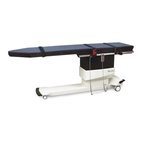
PAIN MANAGEMENT C-ARM TABLE
SERVICE/OPERATION MANUAL
058-870
058-875

!,-61%28%0'327%-26-267%00%7-32%2(34)5%7-32
453')(85)6*357,)*3003:-2+
058-870 Table, Pain Management C-Arm, 115 VAC
058-875 Table, Pain Management C-Arm, 230 VAC
!"!
Featuring a large radiolucent area, motorized actuation of
height, lateral roll and Trendelenburg motions, the Pain
Management C-Arm Table is ideal for pain care applications.
A portable hand-held controller and optional foot-operated
controller can be positioned for convenient access from any
point around the table. The portable hand-held and optional
foot-operated controllers offer the freedom to adjust height,
lateral roll, and Trendelenburg motions from locations away
from the table, or when hands are busy with other functions.
The hand-held controller hangs on an accessory rail when
not in use.
Designed for procedures where stability, access, and pre-
cise, quiet, vibration-free positioning are essential, the Pain
Management C-Arm Table is excellent for image-guided pro-
cedures. A cantilevered low attenuation carbon fiber tabletop
accommodates portable or ceiling-suspended C-Arms. The
radiolucent area is free of cross members, allowing full fluo-
roscopic visualization and unobstructed C-Arm positioning.
Functional design provides complete access with reduced
radiation exposure to clinicians. Patient comfort and stability
are assured by two-inch thick table padding and three
adjustable straps with Velcro® hook and loop fastening. A
face cutout is provided for prone positioning.
NOTE: The Pain Management C-Arm Ta le ta letop is
made of car on fi er. This material, as used in this product,
is certified to meet all the requirements of radiation perform-
ance standards of 21 CFR Su chapter J.
Figure 1. Parts and adjustment mechanisms.
1. Hand-Held Controller
2. Foot End Locking Brakes and Swivel Casters
3. Head End Caster Brake Locking Bar
! !"!
CAUTION: Refer to instruction manual efore oper-
ating or servicing system.
ATTENTION: Se référer à la notice d’utilisation
avant d’utiliser l’equipement.
CAUTION: Hospital grade plug to e plugged into
a hospital grade receptacle only to achieve ground-
ing relia ility.
ATTENTION: La fiche de qualité húpital ne doit Ítre
ranchÈe que sur une prise de courant de qualité
hÙpital, pour une mise á la terre fia le.
CAUTION: Before transferring a patient onto or off
the ta le, ensure all four caster rakes are locked.
Secure the restraining straps immediately after
positioning the patient on the ta le.
ATTENTION: Avant le transfert du patient sur la
ta le ou hors de la ta le, síassurer que les quatre
freins des roulettes sont loqués. Fixer les
lanières díimmo ilisation dès quíon a positionné le
patient sur la ta le.
CAUTION: The restraining straps are not intended
to restrain an uncontrolled patient.
ATTENTION: Les laniéres díimmo ilisation níont
pas pour o jet líimmo ilisation díun patient hors
de contrúle.
!
!
!
!
!
!
!
!

!,)3'/-2+5%/)6%2( :-9)0%67)56
(See Figures 2 and 3.)
The locking brakes and swivel casters allow this table to
glide effortlessly on hard surfaces and across firm rugs.
The foot end casters are locked from either side of the
table while the head end casters are locked together using
the Head End Caster Brake Locking Bar.
1. To release the lock on the brakes and swivel casters at
the foot end of the table, use your toe to lift up on the foot
end caster brake locking lever on either side of the table.
2. To lock the foot end brakes and swivel casters, step
down on the foot end caster brake locking lever on
either side of the table.
3. To lock the brakes and swivel casters for the head end
of the table, use your toe to press down on the head
end caster brake locking bar.
4. To release the head end brake and swivel casters, use
your toe to lift up on the head end caster brake locking bar.
Figure 2. Foot End Locking Brakes and Swivel Casters.
NOTE: The head end caster rake locking ar, when
pressed down in the lock position, raises the head end
casters slightly off the ground.
Figure 3. Head End Caster Brake Locking Bar.
"6-2+7,)%2()0(3275300)5
The hand-held controller may be used to adjust table
height, Trendelenburg/Reverse Trendelenburg and lateral
roll positioning. When not in use, the hand-held controller
can be hooked onto the metal loop on the restraining strap,
or on the accessory rail.
CAUTION: Before moving the ta letop, e sure that
all I.V. lines, attachments and restraining straps,
etc., are out of the way. Ensure the patient is fully
secured to the ta letop y the restraining straps.
ATTENTION: Avant tout déplacement du dossier,
veiller á en dégager les lignes de goutte-á-goutte
intravéneux, les accessoires, les laniéres díimmo ili-
sation, etc. Síassurer que le patient est solidement
fixé au dossier á líaide des laniéres díimmo ilisation.
To adjust the table position, press and hold the appropriate
switch on the hand-held controller. The tabletop will move or
rotate in the direction indicated by the switch. Release the
switch when the tabletop achieves the desired position.
NOTE: The ta le can perform only one motorized function
(i.e. raising or lowering the ta letop, lateral roll,
Trendelen urg/Reverse Trendelen urg at a time. If you
press a second utton on the hand-held controller (or the
foot controller) while the ta le is already performing a
motorized function the ta letop movement will stop. At that
point, you will need to release all uttons efore you can
resume the selected function.
NOTA: La ta le ne peut exécuter quíun seul déplacement
motorisé á la fois (p. ex.: élévation ou a aissement du
dossier, rotation á gauche ou á droite sur líaxe longitudinal,
position de Trendelen urg / position de Trendelen urg
inversée). Le fait díappuyer sur un second outon de la
commande á main (ou sur une seconde pédale) en cours
de déplacement de líappareil provoque líarrÍt du mouve-
ment du dossier. Il faut alors rel‚cher tous les outons
avant de reprendre la fonction choisie.
#30)47-32%0
The adjustable height I.V. pole should be installed onto the
accessory rail. Loosen the I.V. pole locking knob at the
base of the slide block and slide the block and pole onto
the accessory rail until it is in the desired position. Tighten
the locking knob to secure the pole.
To adjust the height of the I.V. pole, loosen the height
adjustment locking knob and raise or lower the top section
of the pole to the appropriate height. Tighten the locking
knob to secure.
3372(
3'/-2+
5%/)6%2(
:-9)0%67)56
!
!
)%(2(
%67)55%/)
3'/-2+%5

SAFETY GUIDELINES
1. Secure restraining straps immediately after placing
the patient on the ta le. The restraining straps prevent
the patient from rolling off the side of the ta le.
NOTE: The restraining straps are not intended to
restrain an uncontrolled patient.
2. Always lock the casters efore moving a patient
onto or off the ta le.
3. This ta le is rated to support patients weighing up
to a maximum of 500 pounds.
CONSIGNES DE SECUrITE
1. Fixer les laniëres díimmo ilisation et les laniëres de
cheville immédiatement aprës avoir placé le patient sur
la ta le. Les laniëres de cheville empÍchent le patient de
glisser sous la ta le en position de Trendelen urg. Les
laniëres díimmo ilisation empÍchent le patient de rouler
par-dessus le cúté de la ta le.
NOTA: Les laniëres díimmo ilisation níont pas pour
o jet líimmo ilisation díun patient hors de contrúle.
2. Toujours loquer les roulettes avant de faire monter
le patient sur la ta le ou de líen faire descendre.
3. La ta le est certifiée comme pouvant supporter un
patient pesant au plus 227 kg (500 l ).
!
The Biodex Pain Management C-Arm Table is virtually
maintenance free. By following the instructions below at
suggested time intervals, or as often as necessary, your
table will remain in “like new” condition.
1. As required, clean all exterior painted surfaces, tabletop
and restraining straps with a mild detergent solution.
2. Wheels and wheel locks should remain free of foreign
materials and dirt accumulation. Keeping wheel assemblies
free of this matter will ensure smooth table transportation
and free lock/unlock wheel operation.
CAUTION: Disconnect power from source efore remov-
ing panel or covers. Relia le grounding achieved only y
connecting this unit to an equivalent marked hospital only
or hospital grade receptacle.
ATTENTION: Déconnector la prise secteur avant
d’ouvrir le coffret. Une terre fia le ne peut étre
o tenue que par la connexion à une prise secteur de
qualité hospitalière.
!
-1)26-326 93" l x 26" w (233 x 66 cm) with R
accessory rails
!%&0)734 90" l x 24" w (228.6 x 61 cm)
%(-308')275)%
60" l x 24" w (152.4 x 61 cm) unobstructed head to
accessory rail
4" l x 17.5" w (10.1 x 44 cm) additional, between
accessory rails
%(-308')275)%!37%0)2+7, 64" l (160 cm)
!%&0)734%7)5-%0 Carbon fiber with integral head section
%775)66 2" thick (5 cm)
77)28%7-32
!%&0)734 .7 mm Aluminum equivalence
%775)66 .5 mm Aluminum equivalence
37-326
)-+,7 (.867%&0) 30" to 40" (75 to 100 cm)
!5)2()0)2&85+ 0° to 20°
)9)56)!5)2()0)2&85+ 0° to 20°
%7)5%0300 0° to 20°
3275306
%2(327530 activates height, lateral roll and
Trendelenburg motions
47-32%0
337327530activates height, lateral roll and
Trendelenburg motions
$,))06
Head End – 3" (7.62 cm) swivel casters, integral locking
system on base
Foot End – 5" (12.7 cm) swivel casters with
central locking
'')6635;%-06 Standard R accessory rails
30" x 1.12" x .375" (75 x 2.86 x .95 cm) mounted near foot
end of table
%7-)27)675%-276Three body straps
-2-6,Powder coat
%7-)27%4%'-7; 500 lb (227 kg); weight tested to four
times the patient load rating.
3:)5 115 VAC or 230 VAC
$%55%27; one year
)57-*-'%7-326 UL-2601-1®, CAN/CSA©
C22.2 No.: 601-1-M90,
EN 60601-1 and IEC 60601-1-2
058-870 Table, Pain Management C-Arm, 115 VAC
058-875 Table, Pain Management C-Arm, 230 VAC
!
058-877 Controller, Foot
056-850 IV Pole, Rail Mounted
058-848 Catheter Tray Extension (removable)
056-865 Arm Board, Carbon Fiber, one arm
056-866 Arm Board, Carbon Fiber, two arms
Authorized European Community Representative:
Emergo Europe
Molenstraat 15
2513 BH, The Hague
The Netherlands
!
!
!
!
0
TYPE BEQUIPMENT
EC REP

!


BIODEX
Biodex Medical Systems, Inc.
This manual suits for next models
1
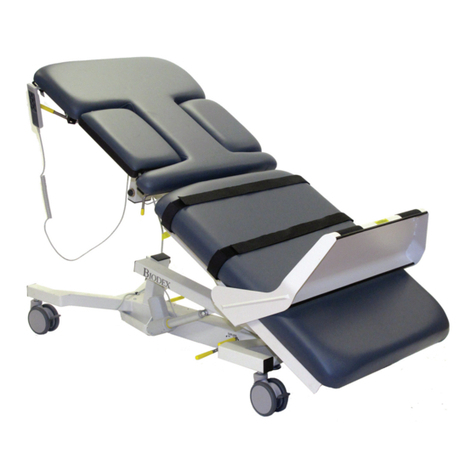
Other biodex Indoor Furnishing manuals
Popular Indoor Furnishing manuals by other brands

Essential Home
Essential Home 0-08612933-5 owner's manual
Isotra
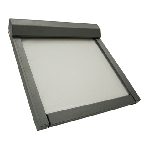
Isotra VERANDA HRV08-ZIP MEASUREMENT AND ASSEMBLY MANUAL
EverDesk+
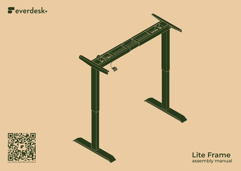
EverDesk+ Lite Frame Assembly manual

Julian Bowen Limited
Julian Bowen Limited SAN106 Assembly instructions
Habitat
Habitat Blyth 801279 manual
Mercado Medic
Mercado Medic REAL 9500 INSTRUCTIONS FOR ASSEMBLY, USE & CARE
