biodex ATOMLAB 500 Operation manual

!
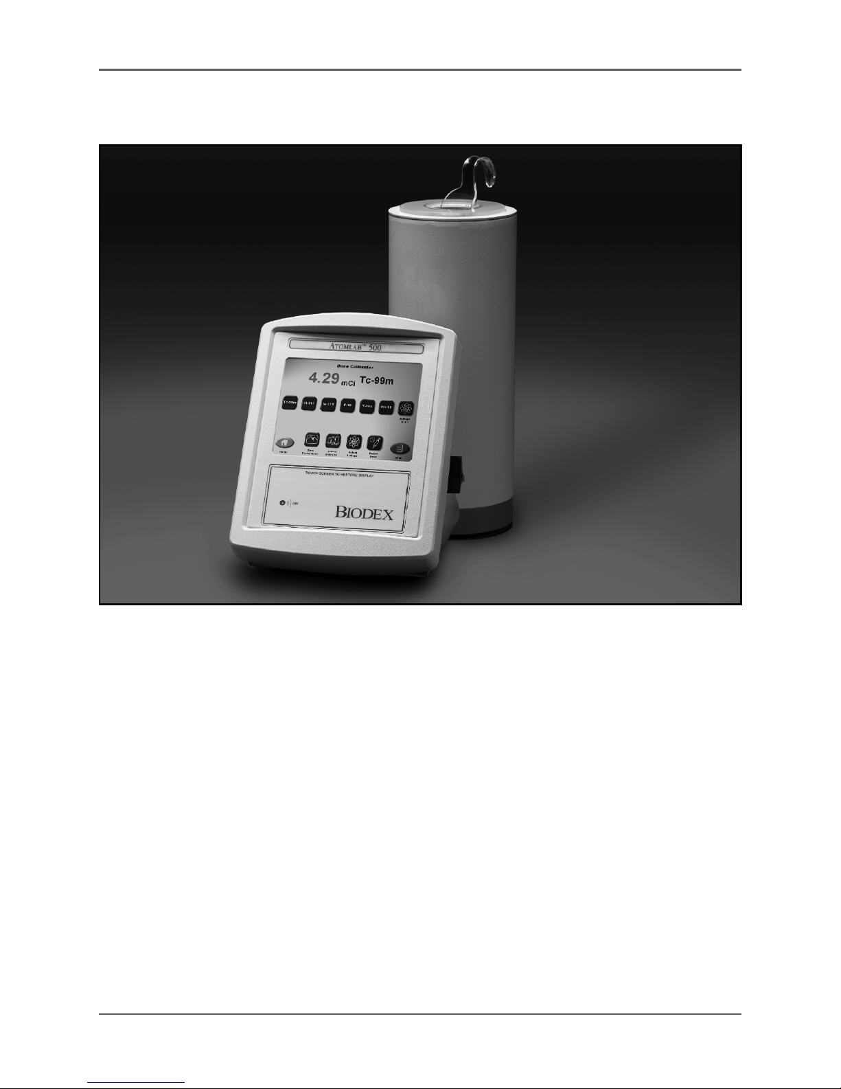
ATOMLAB 500 DOSE CALIBRATOR
OPERATION AND SERVICE MANUAL
086-330
FN: 10-096 Rev G 3/16
!
2ATOMLAB 500 DOSE CALIBRATOR
Atomlab 500 Dose Calibrator
This manual contains operating procedures for the following Biodex product:
#086-330 Atomlab 500 Dose Calibrator

!
Biodex Medical Systems, Inc. © 2016 3
Table of Contents
Page
• Definition of Symbols ............................................................................................................. 6
• Before Proceeding ................................................................................................................ 7
• Product Certifications and Classifications..............................................................................10
• Important Safety Information................................................................................................11
• Unpacking Instructions.........................................................................................................13
• Warranty ............................................................................................................................ 14
1. Introduction................................................................................................................................................... 17
- Introduction.................................................................................................................. 17
- Intended Use ................................................................................................................ 17
- Indications For Use ....................................................................................................... 17
- Description................................................................................................................... 18
2. Installation..................................................................................................................................................... 21
- Operating Requirements ............................................................................................... 21
- Cable Connections ........................................................................................................ 23
- Power Up ...................................................................................................................... 25
- Save The Packing Material ............................................................................................. 26
- Maintenance ................................................................................................................. 26
- Password Protection...................................................................................................... 26
3. Dose Calibrator Operation ...................................................................................................................... 27
- Basic Key Functions....................................................................................................... 27
- The Dose Calibrator Program ........................................................................................ 28
- Counting An Isotope..................................................................................................... 29
- Changing The Selected Isotope ..................................................................................... 31
- Isotope Response Time ................................................................................................. 32
- Zero Background........................................................................................................... 32
- Large Transition During Initialization- Select Detector.................................................... 34
- Select Detector ............................................................................................................. 34
- Select Isotope ............................................................................................................... 35
- Determining Dial Value Adjustments............................................................................. 36
4. Atomlab 500 Utilities................................................................................................................................. 39
- System Configuration...................................................................................................... 40
- Detector Locations ........................................................................................................ 41
- Serial Number ............................................................................................................... 42
- Facility .......................................................................................................................... 43
- Date/Time .................................................................................................................... 44
- Activity Units ................................................................................................................ 45
- Time Format ................................................................................................................... 45
- Screen Saver ................................................................................................................... 45
- LCD Brightness ............................................................................................................... 45
- Tone Volume .................................................................................................................. 45
- Printer Settings ............................................................................................................... 46
- Staff Members............................................................................................................... 47

!
4ATOMLAB 500 DOSE CALIBRATOR
Page
- Web Server Settings ........................................................................................................48
- Dose Calibration Configuration .......................................................................................49
- Isotope List ................................................................................................................... 50
- Setup Routine Isotopes ................................................................................................. 52
- Setup Button Isotopes ................................................................................................... 54
- Add Isotope.................................................................................................................... 55
- Remove Isotope ............................................................................................................ 56
- Change Dial Value .......................................................................................................... 57
- Set Acceptance Variance................................................................................................. 58
- Sealed Source Setup ....................................................................................................... 59
- Set Background Counting Time ...................................................................................... 63
- Label Printing Preferences .............................................................................................. 65
- Setup Isotope And Kit List .............................................................................................. 66
- Low Activity Resolution .................................................................................................. 69
- Volume Decimal Digits ................................................................................................... 69
- System Maintenance....................................................................................................... 70
- Data Management .......................................................................................................... 71
- USB System Backup ........................................................................................................ 75
- USB System Restore........................................................................................................ 76
- Event Logger .................................................................................................................. 77
- System Test.................................................................................................................... 78
- To Change ID.............................................................................................................. 79
- Detector Status............................................................................................................... 79
- Detector Management .................................................................................................... 80
- Source Detection Threshold ........................................................................................... 81
- Touch Screen Calibration................................................................................................ 82
- Updating The System Firmware ...................................................................................... 83
5. Nuclear Pharmacy........................................................................................................................................ 85
- Moly Assay (Moly Breakthru) .......................................................................................... 86
- Half Life Verification ...................................................................................................... 89
- Enter Isotope Into Inventory........................................................................................... 97
- Enter An Isotope Other Than Tc-99m Into Inventory ....................................................... 97
- Enter Tc-99m Into Inventory With Moly........................................................................... 100
- Enter Tc-99m Into Inventory Without Moly...................................................................... 105
- Kit Preparation ............................................................................................................... 108
- Draw Patient Dose .......................................................................................................... 112
- Moly Transfer ................................................................................................................. 116
- Draw Patient Dose From Inventory ................................................................................. 117
- Inventory Kit List ............................................................................................................ 118
- Tec-Control Paper Chromatography .............................................................................. 120
- Future Dose Calculation ................................................................................................. 122
- Volume Dose Calculation ............................................................................................... 125

!
Biodex Medical Systems, Inc. © 2016 5
Page
6. Dose Calibrator Quality Assurance...................................................................................................... 129
- QA Dose Calibrator ....................................................................................................... 129
- Daily Constancy Test ..................................................................................................... 130
- Expanded Constancy Test.............................................................................................. 132
- Geometry Test .............................................................................................................. 135
- Accuracy Test ............................................................................................................... 139
- View Constancy Data ..................................................................................................... 143
- View Expanded Constancy Data ..................................................................................... 146
- View Geometry Data...................................................................................................... 148
- View Accuracy Data ....................................................................................................... 150
- Linearity Testing ........................................................................................................... 152
- Automated Decay Test .................................................................................................. 154
- Linearity Automated Decay Test.................................................................................... 160
- Semi-Automated Manual Decay Test .............................................................................. 163
- Manual Decay Test ........................................................................................................... 170
- Decay Test Data .................................................................................................. 174
- Lineator Initial Test.............................................................................................. 176
- Lineator Test ....................................................................................................... 178
- View Lineator Data .............................................................................................. 180
- Calicheck Initial Test............................................................................................ 182
- Calicheck Test ..................................................................................................... 185
- Calicheck Test Data ............................................................................................. 188
7. Glossary .......................................................................................................................................................... 189
Appendices:
A. Troubleshooting Procedures................................................................................... 188
B. Display Diagnostics For 400/500 Series ................................................................. 195
C. Specifications
................................................................................................................. 199
D. Decay Calculations .......................................................................................................... 203
E. Calibration Values ........................................................................................................... 211
F. Calibration and Traceability............................................................................................. 217
G. Serial Communications Interface ..................................................................................... 219
H. Conformance To Standards ............................................................................................. 227
I. Determining Dial Values .................................................................................................. 231
J. Quality Assurance Testing of Atomlab Calibrators ........................................................... 235
K. Tec-Control Formulas ...................................................................................................... 243
L. Replacement Parts........................................................................................................... 245
M. Schematics ...................................................................................................................... 247

!
6ATOMLAB 500 DOSE CALIBRATOR
Definition of Symbols
The following symbols and their associated definitions are used and
implied throughout this manual.
Symbol Definition
Carefully read these instructions prior to use
Caution
General Warning
General Mandatory Action
Dangerous Voltage
“On” Power
“OFF” Power
Earth (ground)
Alternating Current
Fuse
USB Connector/Cable
Waste in Electrical Equipment
Date of Manufacture
Type B Applied Part
CE Mark
CE Mark for products with EC Certificate
Certified for Safety by ETL Intertek

!
Biodex Medical Systems, Inc. © 2016 7
Before Proceeding
NOTE: The warnings, cautions and instructions provided in this manual must be read,
followed and kept available for consultation at all times. Observing the information,
instructions and procedures presented throughout this manual is essential for using the
Atomlab 500 Dose Calibrator both properly and safely.
Specific Cautions
• Allow only qualified, trained personnel to operate or service the Atomlab 500.
• If the equipment is used in a manner other than specified in this operation manual,
the protection provided by the equipment may be impaired and results could be
compromised.
• The display operates on low voltage and the power supply auto-ranges from 100 to
240 volts input current. The detector steps up the current to increase the high
voltage required to operate the detector. (Never open the detector. The detector
should only be opened by experienced, qualified personnel.)
• Except when using the Moly Shield, the well liner and dipper must be used for all
Atomlab 500 Dose Calibrator measurements.
• The Moly Shield is used with the supplied metal shield for proper placement within
the dose calibrator detector. Always use the well liner.
• The Atomlab Dose Calibrator is designed for use with specific printers. Contact
Biodex for compatible printers.
• Never store sources in the dose calibrator except during a linearity test, as the
sources will lengthen the time needed to perform a Zero Background once the source is
removed from the detector.
• The pre-set dial values noted in Appendix E are password protected but can be
changed by the user. Multipliers are not used with the Atomlab dose calibrators.
• Leave the Atomlab Dose Calibrator power on so that the detector remains stable and
can quickly provide accurate measurements.
• A sealed source should be used to check the constancy of the system each day.
Prudences Spécifiques
• Permettez au personnel seulement autorisé, entraîné de faire marcher ou assurer
l'entretien de l'Atomlab 500.
• Si l'équipement est utilisé dans une manière autre qu'indiqué dans ce manuel
d'opération, la protection fournie par l'équipement peut être diminuée et les résultats
pourraient être compromis.
• L'étalage opère sur le voltage bas et les auto-gammes d'alimentation électrique de
100 courant de contribution de volts au courant de contribution de 240 volts. Le
détecteur augmente le courant jusqu'à ayez le haut voltage pour faire marcher le
détecteur. N'ouvrez jamais le détecteur. Cela devrait être fait seulement par le
personnel de service expérimenté, qualifié.

!
8ATOMLAB 500 DOSE CALIBRATOR
• Sauf lorsque en utilisant le Bouclier de Moly, Bien le Paquebot et le Cincle doivent être
utilisés pour tous Atomlab 500 Dose mesures de Calibrator.
• Le Bouclier de Moly est utilisé avec le bouclier en métal fourni pour le placement
Nécessaire dans la dose détecteur de calibrator. Utilisez toujours Bien le paquebot.
• la dose Atomlab calibrator est conçue à l'utilisation avec les imprimantes spéci-
fiques. Contacter Biodex pour les imprimantes compatibles.
• ne conservez jamais des sources dans la Dose Calibrator sauf pendant une Épreuve
de linéarité, comme le les sources s'allongeront le temps devait exécuter un fond
zéro une fois la source est enlevé du détecteur.
• les valeurs de cadran programmées notées dans l'Appendice E sont le mot de passe
protégé, mais peuvent être changé par l'utilisateur. Les multiplicateurs ne sont pas
utilisés avec la Dose Atomlab Calibrators.
• Quittez la Dose Atomlab le pouvoir de Calibrator SUR pour que le détecteur reste
ferme et peut vite fournir des mesures exactes.
• une source cachetée devrait être utilisé pour vérifier la Constance du système chaque
jour.
WARNING: The unit contains lead for shielding the detector from background radiation.
Additional lead shielding can be used outside the detector to further reduce background
radiation. The lead should be disposed of in accordance with local and national
regulations when disposing of the unit.
AVERTISSEMENT: l'unité contient l'avance pour protéger le détecteur du rayonnement
ambiant. Le premier fait de protéger supplémentaire peut être utilisé à l'extérieur du
détecteur pour davantage réduire le rayonnement ambiant. L'avance devrait être
disposée conformément à local et national les règlements en se débarrassant de l'unité.
WARNING: All activities and count values on the sample reports in this manual are for
illustration purposes only. They do not represent actual study values.
AVERTISSEMENT: Toutes les activités et les valeurs de compte sur les rapports de
promotion dans ce manuel sont pour les buts d'illustration seulement. Ils ne représentent
pas de valeurs d'étude réelles.
CAUTION: Unauthorized modifications to this product are not permitted and will void
the manufacturer’s warranty. Unauthorized modification of the product may result in a
hazard to the user and/or patient. Do not modify this equipment without authorization
from the manufacturer.
ATTENTION: Les modifications faites sans autorisation à ce produit ne sont pas per-
mises et va faire le vide la garantie du fabricant. La modification faite sans autorisation
du produit peut s'ensuivre dans un hasard à l'utilisateur et-ou le patient. Ne modifiez pas
cet équipement sans autorisation du fabricant.

!
Biodex Medical Systems, Inc. © 2016 9
CAUTION: The Atomlab Dose Calibrator is intended to measure the activity of a
radioactive source of a known isotope. This measurement may be for purposes of
determining or verifying a radiopharmaceutical dose for nuclear imaging or nuclear
medicine. This measurement may also be for the purpose of determining the radioactivity
of a sample for dose calibrator constancy and Accuracy Testing or to measure other non-
medical radioactive samples.
ATTENTION: La Dose Atomlab Calibrator est destinée pour mesurer l'activité d'une
source radioactive d'un isotope connu. Cette mesure peut être pour les buts de
détermination ou du fait de vérifier une dose radiopharmaceutical pour le fait de
refléter nucléaire ou la médecine nucléaire. Cette mesure peut aussi être pour le but de
déterminer la radioactivité d'un échantillon pour la dose calibrator la constance et la
mise à l'essai d'exactitude ou mesurer d'autres échantillons radioactifs non-médicaux.
Training
On-site installation and training is optional. The operation manual includes assembly and
operating instructions. An applications training webinar is available on the internet at no charge;
application questions can be directed to our service department during business hours.

!
10 ATOMLAB 500 DOSE CALIBRATOR
Product Certifications And Classifications
This product has received the following certifications and falls within the following
classifications:
• ETL Listed Electrical Equipment, Laboratory Use; Part 1, General Requirements for Safety
conforms to UL 60601-1, CAN/CSA C22.2 No: 601-1-M90, IEC 60601-1, IEC 60601-1-4
and IEC 60601-1-2 and CE Marked.
• FDA Class II Equipment
• EC Certificate: EC #4132458
• Type B Applied Part
0413
• Electromagnetic Compatibility: This equipment complies with the Medical Equipment
ICC 60601-2 EMC Standard.
NOTE: Circuit diagrams for this product are provided in the Schematics section at the back of
this manual.
Authorized European Community Representative:
EC REP
Emergo Europe
Molenstraat 15
2513 BH, The Hague
The Netherlands

!
Biodex Medical Systems, Inc. © 2016 11
Important Safety Information
CAUTION: Federal Law restricts this device to sale by or on the order of a physician,
pharmacist or other licensed professional.
ATTENTION: La Loi Fédérale restreint cet artifice à la vente par ou sur l'ordre de un
docteur, le pharmacien ou d'autre professionnel agréé.
Follow the unpacking and assembly instructions document.
Before using this device, read the entire operation manual carefully. Failure to read the
manual may result in user error or inaccurate data. Be sure to save all provided
documents for future reference.
Make certain to understand all warning and caution labels as explained in the Before
Proceeding section of this manual.
This product should be used only as specified in this operation manual.
For product specifications, refer to the table of contents.
This medical electrical equipment required special precautions regarding EMC and
Needs to be installed and placed into service according to EMC information provided in
this manual. Electromagnetic compliance definition is provided in Appendix H.
It is recommended that the Quality Assurance Testing of Atomlab Dose Calibrators be
performed as presented in Appendix J.
For cleaning and maintenance instructions, refer to Table of Contents.
CAUTION: Operation for: 100-240 VAC, 50/60 Hz.
ATTENTION: Opération pour: 100-240 VAC, 50/60 Hz.
WARNING: Only use approved power supplies.
AVERTISSEMENT: Utilisez Seulement des alimentations électriques approuvées.

!
12 ATOMLAB 500 DOSE CALIBRATOR
CAUTION: To avoid risk of electric shock, this equipment must only be connected to
supply mains with protective earth.
ATTENTION: Pour éviter le risque de choc électrique, cet équipement doit uniquement
être connecté à un approvisionnement conduites avec la terre protectrice.
CAUTION: The plug is considered the method of disconnecting the product from mains
power. Do not place the product in a position where the plug is not easily accessible.
ATTENTION: Le bouchon est considérée comme la méthode de déconnexion du produit
d'alimentation. Ne placez pas le produit dans une position où le bouchon n'est pas
facilement accessible.
CAUTION: The product is intended to remain in one location during operation.
ATTENTION: Le produit est voulu rester dans un emplacement pendant l'opération.
!
Biodex Medical Systems, Inc. © 2016 13
Unpacking Instructions
Shipping Cartons
The Atomlab 500 Dose Calibrator and its respective components are carefully packed in two
cartons. One carton contains the display unit and accessories; the other carton contains the
detector unit. Both are shipped in an over-pack.
NOTE: Prior to removing any of the cartons from the shipping box, visually inspect the box and
the inside packing for damage. If any damage is noted, do not unpack the contents. Notify the
carrier immediately so that a claim can be made if necessary, and contact your Biodex Medical
Systems Sales Representative. If there is no visible damage, remove the cartons and place them on
a table or to the side. We suggest removing the display unit carton first.
NOTE: Before deciding on a location to set up your Atomlab for operation, be sure to
read Chapter 2 on installation. This chapter notes operating and environmental
requirements, and offers several tips on choosing a location for your dose calibrator.
The Display Unit Carton:
In addition to the display unit itself, this carton contains the Atomlab's Operation Manual, all the
necessary connection and power wires needed to run the system, and a report of calibration.
The Detector Unit Carton:
CAUTION: The carton labeled DETECTOR UNIT is very heavy, ~38 pounds. Severe damage
to the unit may result if this carton is dropped. Remove the detector from the carton and
carefully place it on the table or other counter where you will set up and use your
Atomlab unit. Make certain the tabletop will support a minimum of 300 pounds. We
suggest that you place the carton on its side so that you can slide the Detector Unit out of the
carton onto its side. Now, stand the detector up onto its base. Inserted into the
Detector Well should be a Detector Well Liner.
ATTENTION: Le carton étiqueté UNITÉ DE DÉTECTION est très lourd, ~38 livres. Cet appareil
Peut subir de sérieux dommages s’ii est échappé. Retirez le détecteur de son carton et utiliserez le
avec prudence sur la table ou le computoir où vous installerez et utiliserez l’unité Atomlab.
Assurezvous que la table supportera un minimum de 300 livres. Nous suggérons que vous
placiez le carton sur son côté afin que vous puissiez faire glisser L’UNITÉ DE DÉTECTION du
carton à
sa base. Dans la chambre du calibrateur vous devriez trouver un manchon pro-
tecteur. Un échantillon en plastique est emballé avec l’unité de présentation.
Save The Packing Material
Do not discard the packing materials, cartons or shipping boxes.
This material was designed especially for the safe shipment of your Atomlab 500 Dose
Calibrator. You will need them to return any of the Atomlab components in the future for
updates, calibration or repair.

!
14 ATOMLAB 500 DOSE CALIBRATOR
Atomlab 500 Dose Calibrator Warranty
1. I
nstrumentation
A. This equipment and its accessories are warranted by BIODEX MEDICAL SYSTEMS, INC.,
against defects in materials and workmanship for a period of two years from the date of
shipment from BIODEX MEDICAL SYSTEMS, INC. During the warranty period, BIODEX
MEDICAL SYSTEMS, INC. will in its sole discretion, repair, recalibrate or replace the
equipment found to have such defect, at no charge to the customer.
EXCEPT AS STATED ABOVE, THERE ARE NO WARRANTIES, EXPRESSED OR IMPLIED,
INCLUDING WITHOUT LIMITATION WARRANTIES OR MERCHANTABILITY OR
FITNESS FOR
USE. BIODEX DOES NOT ASSUME LIABILITY FOR INCIDENTAL,
CONSEQUENTIAL OR INDIRECT
DAMAGES INCLUDING LOSS OF USE, SALES,
PROFITS OR BUSINESS INTERRUPTION.
B. This warranty does not apply if the product, as determined by BIODEX MEDICAL
SYSTEMS, INC., is defective due to abuse, misuse, modification or service performed by
other than a BIODEX MEDICAL SYSTEMS, INC. Authorized repair and calibration facility.
Misuse and abuse include, but are not limited to, subjecting limits and allowing
the equipment to become contaminated by radioactive materials.
C. In order to obtain warranty repair service, the equipment must be returned freight
pre-paid to one of our facilities. The return material authorization (R.M.A. #) should be
included, along with a statement of the problem. Equipment will be returned
transportation prepaid.
2.
Calibration
A. Instruments are warranted to be within their specified accuracy at the time of shipment.
If a question arises and BIODEX MEDICAL SYSTEMS, INC. determines that the initial
calibration is in error, the instrument will be recalibrated at no charge.
B. Mechanical products are warranted to meet written specifications and tolerances at the
time of shipment.
3. Warranty Is Non-Transferable.
4. Non-Warranty Service
A. Repairs and/or replacements not covered by this warranty may be performed by
BIODEX MEDICAL SYSTEMS, INC. At a factory authorized service location. Estimates of
repair charges may be requested, however, a charge for estimate preparation may apply if
the repair is later not authorized by the customer.
B. The cost of transportation into and out of the service location will be the responsibility
of the customer.

!
Biodex Medical Systems, Inc. © 2016 15
Service Procedure
If you think you have a service problem, take the following action.
1. Check to see that the problem occurs more than once.
2. Check the instruction manual and operations procedure.
3. Check the instruction manual troubleshooting Guide.
If you still think you have a service problem, call BIODEX MEDICAL SYSTEMS, INC.,
S
ervice Department at (800) 224-6339.
Keep Yourself And The Phone Next To The Equipment.
1. Service will ask you for a brief description of the problem. We will ask specific questions
about the malfunction that occurred. This diagnostic process may take a few minutes,
so call us when you have time to spare.
2. After taking the information, we will advise on the action we will take.
3. Sometimes service personnel must consult with engineering and it may take time to get
back to you. Be sure to let the service representative know your schedule so that we can call at
a convenient time.
4. The return call may be from a person other than whom you first reported the problem to.
5. After analyzing the problem, we will decide if the unit must be returned to us for repair,
or replacement parts will be sent.
6. If unit must be returned, it will be given a return material authorization (R.M.A. #)
number by us. Pack the system in the carton that it was originally shipped in, or pack it
safely and securely to avoid shipping damage. It is the customer's responsibility for any
damage that occurs during shipping.
7. Non-warranty/non-service contract charges for repair are as follows:
A. Materials
+
B. Time
Service
+
C. Shipping Charges
Contact Information
Biodex Medical Systems, Inc.
20 Ramsey Road, Shirley, New York, 11967-4704
Tel: 800-224-6339 (Int’l 631-924-9000)
Fax: 631-924-9241

!
16 ATOMLAB 500 DOSE CALIBRATOR
!
!
!
Biodex Medical Systems, Inc. © 2016 17
1. Introduction
Intended Use
The Atomlab Dose Calibrator is intended to measure the activity of a radioactive source of a
known isotope. This measurement may be for purposes of determining or verifying a
radiopharmaceutical dose for nuclear imaging or nuclear medicine. This measurement may also
be for the purpose of determining the radioactivity of a sample for dose calibrator constancy and
Accuracy Testing or to measure other non-medical radioactive samples.
Indications For Use
The Atomlab Dose Calibrators are used in nuclear medicine departments, clinics and nuclear
pharmacies to measure radioactive doses for administration to patients. The system is used to
verify the radioactivity of a radionuclide before administration to the patient.
Atomlab Dose Calibrators use an argon gas filled pressurized detector to measure the activity of a
radionuclide source of a known isotope. Their primary application is the measurement of the dose
administered to a patient in nuclear imaging or nuclear medicine. Additionally, there are advanced,
but easy-to-use programs for Nuclear Pharmacy, radiochemistry and radiochromatography.
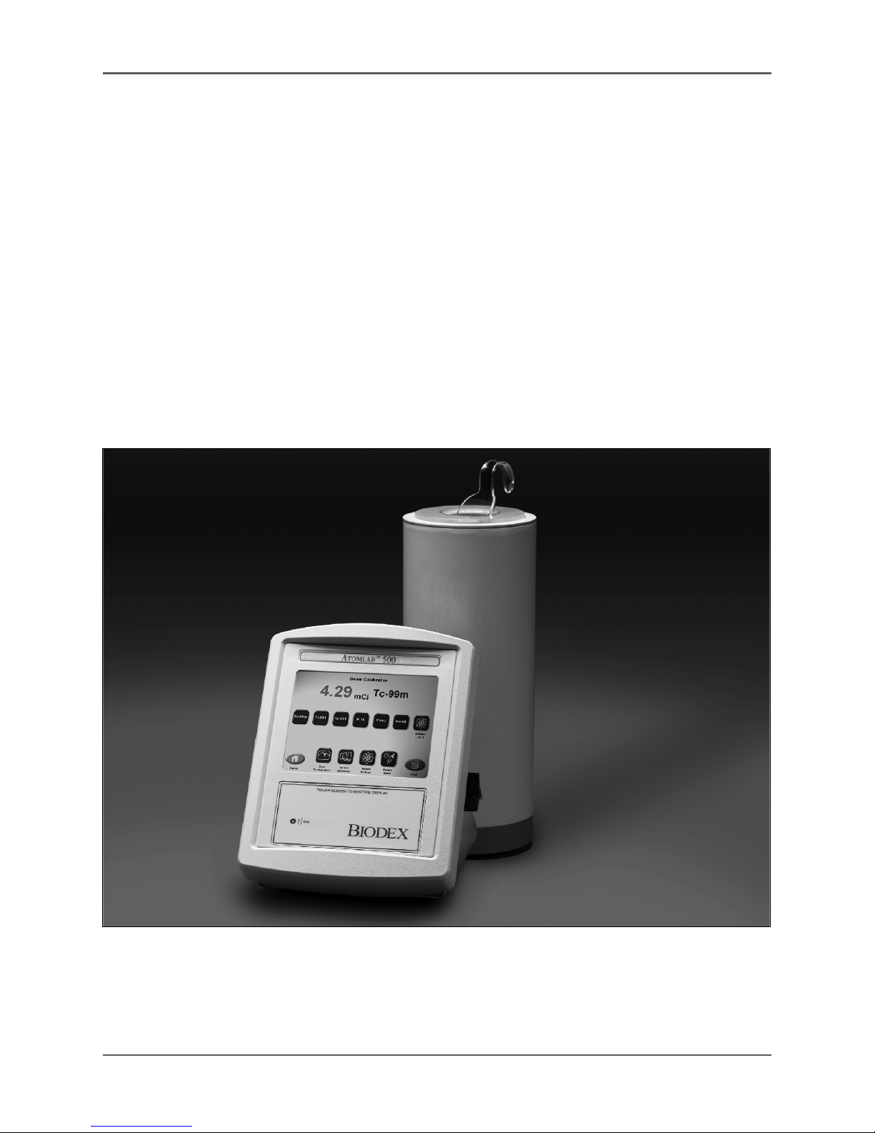
Figure 1.1. The Atomlab 500 features large, easy to read icons, prompts and values on a touch-screen display.

!
18 ATOMLAB 500 DOSE CALIBRATOR
The system consists of a low pressure ionization chamber, electrometer with extraordinary
Linearity and an auto-ranging touch-screen color display. It provides fast, accurate radionuclide
measurements with performance that easily complies with the most stringent regulatory
requirements.
Activity measurements are performed by the microprocessor controlled electrometer located
within the chamber assembly. The chamber is shielded with .25" (6.3 mm) lead. It can be
located up to eight feet away from the display unit. Chamber bias is generated by an electronic
high voltage supply, eliminating the need for expensive battery changes. The display can rest on
a bench or mount on a wall.
Description
There are 12 isotope selection touch keys pre-programmed for the most commonly used radionu-
clides. Any of those keys can be reprogrammed by the user for a desired isotope. There are 88
isotope-specific dial values listed in the library. Dial values can easily be changed if required.
Activity is displayed on the touch-screen color display in either Curie or Becquerel units.
Background correction is performed at the touch of a button. Range selection is automatic from
.01 microcurie to 100 curies of Tc-99m or 25 curies of F-18.
The Detector
The Atomlab detector unit is a well type ionization detector capable of measuring activity as low as
0.01 µCi and as high as 100 curies of Tc-99m or 25 curies of F-18. The detector is surrounded on
all sides and on the bottom with .25-inch lead to both shield you from the source you are measur-
ing and shield the dose calibrator from any ambient radiation. The well type detector was carefully
selected to provide a nearly "4 pi" measuring geometry which means that the radiation detector
nearly surrounds the radionuclide. This allows the Atomlab Dose Calibrator to measure the activity
of a sample no matter what its volume or shape, as long as it fits into the detector well. This is
necessary, for example, when measuring syringe doses when the volume is unimportant. The
detector has electronics and the calibration built into it (the calibrator is built into the detector.)
Therefore, you can connect any Atomlab 500 display to a detector and have a calibrated system.
Detector Well Liner
Placed within the well is a plastic liner to protect the detector from contamination in the event
of the source leaking during measurement. The dose calibrator should always be used with the
well liner.
Source Holder
Radioactive sources are measured by placing them within the well opening of the ionization
detector using the geometry within the detector. Samples contained within vials should be held
in the bottom cup of the sample holder sample holder or syringe/vial dipper. The sample holder
places the radioactive source in the location which is at the proper measurement. Samples within
syringes should be placed in the syringe holder ring on the sample holder. Sources should be
orientated vertically in the source holder. Sources should be placed in the dose calibrator well
within 5 to 15 cm from the bottom of the detector well, as measured without the well liner in
place. The response of the dose calibrator varies +/-0.5% within this region.
Current Measurement
The ionization current is measured by a microprocessor-controlled high impedance electrometer
located within the base of the detector unit.

!
Biodex Medical Systems, Inc. © 2016 19
Rear Panel
On the rear connector panel of the detector unit are two connectors. One is for power and data
communication with the display unit. The other is used to connect to a second detector. The
detector unit can be located up to 20 feet (6.09 meters) away from the display unit. The
standard cable measures eight feet (2.43 meters) in length.
Response
The response of this type of ionization detector has been carefully studied using radionuclides
calibrated at the National Institute of Standards & Technology. The result is a well-defined
energy response curve which is used to determine the calibration values for many different
isotopes with high accuracy. Each detector has been calibrated with a national institute of
standards & technology traceable source. The corresponding calibration value has been stored in
the memory of the detector unit. After calibration, the detector's accuracy is tested with
several sources of differing gamma energies whose activity values are traceable to the National
Institute of Standards & Technology.
The Display Unit
The Atomlab 500 Dose Calibrator display unit consists of function keys and an LCD display that
allows you to make activity measurements. A built-in microprocessor executes commands input via
the touch panel and computes activity values from detector data.
The display unit, with a molded plastic case housing the electronics, has been specifically
designed to perform activity measurements in a laboratory setting. To allow easy fingertip control
of the button the front panel slopes gradually, providing an optimum viewing angle. On the rear
panel of the unit are the power and communication connectors, which remain out of the way as
they are infrequently adjusted.
Measurement Method
The current from the detector is measured in one of three ways, depending upon the order of
magnitude of the current. At low currents, the current from the detector is collected upon a
capacitor in the feedback loop of the electrometer whose capacitance is stable and measured to a
high degree. Voltage measurements are made upon this capacitor many thousands of times per
second. The time period between measurements is accurately calibrated. The second of two
successive values is subtracted from the first, which yields the net voltage change of the capacitor
over that short period of time. Thousands of successive differences are averaged over the course
of one second in order to determine the detector current during that second. After a sufficient
rise in voltage, the charge on the capacitor is emptied, reducing the charge and voltage by a
calibrated amount.
At medium currents, the capacitor will reach its maximum voltage value very quickly, and the
capacitor must be emptied quite often. At these currents, the number of times the capacitor is
emptied per unit time is used to calculate the current from the detector.
At high currents, the capacitor cannot be emptied fast enough. Instead, the switch which controls
when the capacitor is emptied is closed, and the electrometer is nulled. The value of The DAC
which is used to null the electrometer is used to determine the detector current at high currents.
During calibration, multiple measurements are made at current values at which two modes of
current measurement can be used effectively. These calibration measurements are used to set the
calibration parameters of the medium and high current modes so as to meet the linearity required
of the electrometer.

!
20 ATOMLAB 500 DOSE CALIBRATOR
Display Units
When you set your dose calibrator to display activity values in Ci (curies), the system of units,
either µCi, mCi or Ci, will be indicated next to the numeric display. The prefix micro or µ(10-6),
or milli or m (10-3) or curies is automatically selected by the system's microprocessor. For
example, if the numeric value displayed is 12.03, and µCi is indicated, the activity will be
12.03x10⁻⁶ ci or 0.00001203 curies; if 63.9 is displayed and mCi indicated, the activity is
63.9x10⁻³ ci or 0.0639 curies.
In the same manner, when you set the dose calibrator to the international system of units,
Becquerels, either MBq or GBq will be indicated, where the prefix m represents Mega (106) and
G represents Giga (109). The absolute measurement range of the Atomlab Dose Calibrator is
from 0.01 µCi to 100.00 ci of Tc-99m or 25 curies of F-18 (and the equivalent in becquerels).
For example, 12.03 µCi = .445 MBq and 63.9 mCi = 2.36 GBq. If the numeric display reads
0.445 and MBq is indicated, the activity value is 445,000 becquerels; if 2.36 is displayed and
GBq indicated, the activity is 2,360,000,000 becquerels.
Routine Isotopes
The routine radioisotope (isotope selection) keys for the Atomlab 500 include: Tc-99m, TI-201,
I-123, I-131, Cs-137, Co-57, Xe-133, Ga-67, In-111, F-18, Y-90s, and Ba-133. The Co-57, Ba-133 and
Cs-137 buttons are primarily used for accuracy and constancy tests.
Atomlab Dial Values
Equal activities of two different isotopes will generate different amounts of current in the ion
detector due to differences in the energy and particle emitted by the isotopes. Dial values are a
means of calibrating the source activity measured for an isotope due to these differences in
detector current. The amount of current which is produced by a Co-60 source is defined as a dial
value of 5.0; all other isotopes are defined relative to the Co-60 value. Co-60 was chosen as the
defining isotope due to its high energy photon emission and long half-life. The high energy reduces
the effect of container geometry (syringe, vial, etc.) and the long half-life ensures that a single
calibrated source can be used for many calibrations.
The dial value for certain isotopes have been directly measured using NIST calibrated sources
provided from the NIST standard reference materials program. These isotopes include Ga-67,
Y-90, Tc-99m, Mo-99, In-111, I-125, I-131, Xe-133, and TI-201. In addition the Cs-137 dial
value has also been measured directly using a NIST calibrated source. Using the measured
detector response for the isotopes listed above in conjunction with a Monte Carlo model of the
ion detector, detector response curves have been generated. Using information on photon,
electron and positron emission (from Table of Radioactive Isotopes, by Browne and Firestone,
verified with the Nuclear Data Center’s Nudat 2.2 Database), calculated dial values have been
generated for those isotopes for which direct measurement of the dial value was not possible.
Other manuals for ATOMLAB 500
3
Table of contents
Other biodex Test Equipment manuals


