WHALETEQ SECG 4.0 User manual

SECG 4.0| User Manual
WHALETEQ
Single Channel ECG Test System
(SECG 4.0)
User Manual
2021-11-26

SECG 4.0| User Manual
Copyright (c) 2013-2021, All Rights Reserved.
WhaleTeq Co. LTD
No part of this publication may be reproduced, transmitted, transcribed,
stored in a retrieval system, or translated into any language or computer
language, in any form, or by any means, electronic, mechanical, magnetic,
optical, chemical, manual or otherwise, without the prior written permission
of WhaleTeq Co. LTD.
Disclaimer
WhaleTeq Co. LTD. provides this document and the programs "as is" without
warranty of any kind, either expressed or implied, including, but not limited
to, the implied warranties of merchantability or fitness for a particular
purpose.
This document could contain technical inaccuracies or typographical errors.
Changes are periodically made to the information herein; these changes will
be incorporated in future revisions of this document. WhaleTeq Co. LTD. is
under no obligation to notify any person of the changes.
The following trademarks are used in this document:
is a registered trademark of WhaleTeq Co. LTD
All other trademarks or trade names are property of their respective
holders.

3
SECG 4.0 | User Manual
Contents
1Introduction ..................................................................................... 7
1.1 Basic concept .............................................................................. 7
1.2 Standards/Application ................................................................ 8
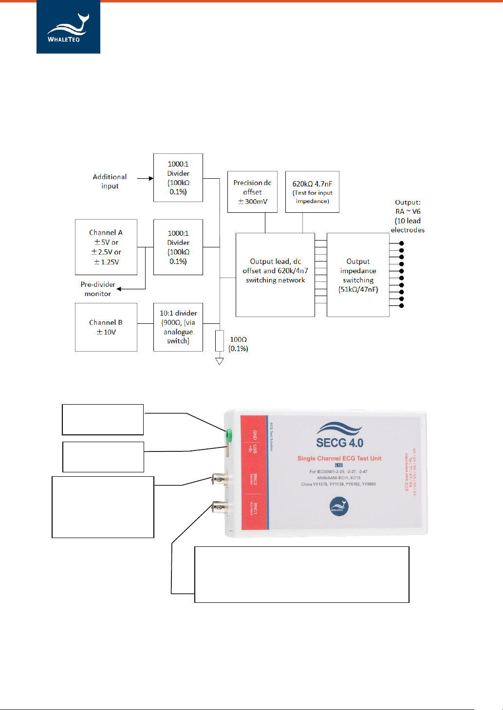
1.3 Block diagram/SECG 4.0 Module overview .............................. 10
1.4 Main specifications ................................................................... 11
2Set up..............................................................................................13
2.1 Software installation................................................................. 13
2.1.1 System requirements................................................................ 13
2.1.2 SECG 4.0 Software Installation ................................................. 13
2.1.3 USB Driver Installation.............................................................. 14
2.1.4 Microsoft .Net Framework 4.0 Installation .............................. 15
2.2 Connecting to the ECG.............................................................. 15
2.3 Environment, noise reduction .................................................. 16
2.4 Firmware Update ...................................................................... 17
2.4.1 Firmware Update Instruction.................................................... 17
2.5 Main Screen .............................................................................. 20
2.6 Description of Functional groups.............................................. 21
2.6.1 Main function (main waveform)............................................... 21
2.6.2 Main Parameters ...................................................................... 23
2.6.3 DC Offset Setting....................................................................... 24
2.6.4 Input Impedance Test ............................................................... 24
2.6.5 Output Lead Electrode.............................................................. 25
2.6.6 Pacing parameters .................................................................... 25
2.6.7 Output graphic display.............................................................. 27
2.6.8 Special functions ....................................................................... 28
2.6.9 Other Function (Auto Pacing, Auto Heart Rate, Cal. Mode)..... 29
2.6.10 Load ECG File ............................................................................ 30
2.7 Software Options –SECG Assistant .......................................... 31
2.7.1 Activate the SECG Assistant Software ...................................... 31
3Testing to IEC and AAMI standards ..................................................33
3.1 Relation between IEC figures and WhaleTeq SECG.................. 33
3.2 Terminals P1, P2 and P6............................................................ 34
4Software Development Kit...............................................................36
5Calibration, software validation.......................................................36

4
SECG 4.0 | User Manual
5.1 Self-Calibration.......................................................................... 40
6Trouble shooting .............................................................................43
7Cautions ..........................................................................................44
8Purchasing Information ...................................................................45
8.1 Standard accessories................................................................. 45
8.2 Purchase software and accessories .......................................... 45
9Version information.........................................................................45
10 Contact WhaleTeq ...........................................................................46

5
SECG 4.0 | User Manual
List of Table
Table 1: Standard/Application........................................................... 8
Table 2: Main Specification ............................................................. 11
Table 3: H/W F/W Version............................................................... 18
Table 4: Main waveform.................................................................. 21
Table 5: Pacing Parameter............................................................... 25
Table 6: Cross-References Between Switches and Terminals......... 33
Table 7: Calibration procedure........................................................ 37
Table 8: Trouble Shooting................................................................ 44
Table 9: Version Information........................................................... 45

6
SECG 4.0 | User Manual
List of Figure
Figure 1: Single-channel Concept ...................................................... 7
Figure 2: Simplified Block Diagram.................................................. 10
Figure 3: SECG 4.0 Module .............................................................. 10
Figure 4: Noise Reduction Environment Setup ............................... 16
Figure 5: Firmware Update Confirmation ....................................... 17
Figure 6: Function Table .................................................................. 18
Figure 7: Update F/W Button. ......................................................... 18
Figure 8: Information Dialog............................................................ 19
Figure 9: Firmware Updating........................................................... 19
Figure 10: Firmware Update Completion........................................ 19
Figure 11: Main Screen.................................................................... 20
Figure 12: Main Parameters ............................................................ 23
Figure 13: DC Offset Setting ............................................................ 24
Figure 14: Input Impedance Test..................................................... 24
Figure 15: Output Lead Electrode.................................................... 25
Figure 16: Pacing Parameter ........................................................... 25
Figure 17: Output Graphic Display .................................................. 27
Figure 18: Special Function.............................................................. 28
Figure 19: Other Function................................................................ 29
Figure 20: Load ECG File .................................................................. 30
Figure 21: Load ECG File Button ...................................................... 30
Figure 22: Activate the SECG Assistant Software Button................ 31
Figure 23: Hardware ID.................................................................... 32
Figure 24: Activate Key.................................................................... 32
Figure 25: Software Assisted Calibration Mode.............................. 37
Figure 26: SECG 4.0 Interface .......................................................... 41
Figure 27: Self-Calibration Setup..................................................... 41
Figure 28: SECG 4.0 ±300 mV DC offset........................................... 42
Figure 29: DC Voltage Verification (300mV).................................... 42
Figure 30: Self-Calibration Setup..................................................... 43
Figure 31: DC Voltage Verification (>300mV).................................. 43

7
SECG 4.0 | User Manual
1Introduction
1.1 Basic concept
The WhaleTeq Single-channel ECG Test System 4.0 (SECG 4.0) provides a
single waveform to one or more lead electrodes of diagnostic, ambulatory, or
monitoring ECGs, for testing IEC/YY/JJG standards. The following diagram
shows the single-channel concept:
Figure 1: Single-channel Concept
Via a SECG 4.0, the system produces arbitrary waveforms (streamed from
the PC with digital to analogue conversion) at up to ±5V, which is then
applied to a precision 1000:1 divider to produce the voltages at up to ±5mV
level (10mVpp). The SECG 4.0 contains resistor/capacitor networks, DC
offset, pacing circuit, and relay switching to provide the full range of single-
channel performance tests in IEC/YY/JJG standards as described in Section
1.2.
The basic range of tests in the standards include, for example:
-Sensitivity (accuracy of the mV/mm indication)
-Frequency response (sine wave, and impulse tests)
-Input impedance
-Noise
-Multichannel cross talk
-Accuracy of heart rate indication
-Pacemaker rejection
-Tall T-wave rejection
RA
LA
LL
RL
V1
V2
V3
V4
V5
V6
ECG device
under test

8
SECG 4.0 | User Manual
For a full list of tests, refer to the standard together with Section 1.2.
The system does not provide:
-CMRR tests (this requires a special noise free box, please refer to
CMRR 3.0 on WhaleTeq website)
-Multichannel waveforms, such as the CSE, AHA, MIT databases (this
requires a multichannel system, please refer to MECG 2.0 on
WhaleTeq website)
1.2 Standards/Application
The following table shows the standards for which this system has been
designed for including any limitations:
Table 1: Standard/Application
Standard
Clause(s)
Limitations / Notes
IEC 60601-2-25:2011
(Diagnostic)
201.12.4: All
performance tests
Except:
◆CMRR test and
baseline noise
➔use WhaleTeq
CMRR 3.0
◆Test referring to
the CTS atlas
(CAL/ANE
waveforms)*, CSE
database
➔use WhaleTeq
MECG 2.0
*Note: for most tests
CAL/ANE waveforms are
alternates. For two tests
may be required
(201.12.4.102.3, test of
lead networks; and
For 201.12.4.101
(large DC offset test),
the SECG is limited to
±1VDC. However, this
is almost certainly
enough to exceed the
point of saturation.
For the test circuit in
figure 201.110, switch
position A is not
provided. This is
considered an error in
the standard due to
the loading effect of
R2. Instead the DC
offset is provided in
series with output as
per Figure 201.106.
(See section 3.2 for
notes on switching
between P1, P2 and
P6.)

9
SECG 4.0 | User Manual
Standard
Clause(s)
Limitations / Notes
201.12.4.105.3 test of
ringing from mains
notch filter)
IEC 60601-2-27:2011
(Patient monitoring)
201.7.9.2.9.101 b), 4)
and 6) (special test
waveforms for Figure
201.101)
201.12.1.101, all
performance tests
except baseline noise
and CMRR (use
WhaleTeq CMRR3.0 for
these tests)
No known limitations
IEC 60601-2-47:2012
(Ambulatory)
201.12.4, all tests except
CMRR (use WhaleTeq
CMRR 3.0 for these
tests)
For all 201.12.1.101
database tests, use
WhaleTeq MECG 2.0 for
these tests.
No known limitations
ANSI/AAMI EC 13
2002/(R)2007/C2008
All performance tests
except CMRR and as
noted left.
See below for Clauses
5.1.4 n) and 5.2.9.1 f),
g) 1
General limitation: this equipment is designed for use with isolated ECG
circuits, as are generally provided for medical ECG. If applied to a non-
isolated circuit, the noise may be excessive.
1
5.1.4 n) Fast QRS: The sampling rate is limited to 0.2ms, some distortion of the pulse is possible
below 6ms.
5. 2.9.1 f), g): Functionality is not included at this time; note the test is not applicable to most ECG
systems

10
SECG 4.0 | User Manual
1.3 Block diagram/SECG 4.0 Module overview
The following is a simplified block diagram of the system inside the SECG 4.0
module:
Figure 2: Simplified Block Diagram
Figure 3: SECG 4.0 Module
Additional input to allow connection to an
external function generator (e.g. analogue type if
aliasing is suspected). Precision divider ensures
that 1V in = 1mV out (±0.2%)
Connects to the
PC via USB 2.0
For noise
reduction
Allows monitoring of
the applied signal
pre-divider
(1V = 1mV output)
(BNC2)
(BNC1)

11
SECG 4.0 | User Manual
1.4 Main specifications
In general, the system has been designed to the standards above, taking
into account Clause 201.5.4 in IEC 60601-2-25 and IEC 60601-2-27. Below
includes these parameters and also other system parameters necessary for
testing. For reference, the system capability is provided.
Table 2: Main Specification
Parameter
Specification
System capability /
notes
Main output voltage
accuracy
±1% for amplitudes of
0.5mVpp or higher
±0.3%
Main output voltage
resolution
(DAC resolution)
2.5µV
In version 4.0, a single
output range is used
Frequency / pulse
repetition rate
accuracy
±1%
±0.1%
Pulse duration / timing
accuracy (excluding
pacing)
±1ms
±0.2ms
Pacing pulse width
accuracy
±5µs
±1µs
Pacing pulse amplitude
accuracy, range
±2mV pulse: ±1%
>2mV pulse: ±10%
Range: ±2mV to
±700mV
±2mV pulse: ±0.3%
100mV pulse: ±1% or
±5mV
Pacing pulse
characteristics
Rise/fall time 5µs
Overshoot <1%
Settling time <1%
Pacing pulse overshoot
(intentional)
Method A according
to IEC 60601-2-27
Resistor tolerance
±1%
±0.5%
Capacitor tolerance
±5%
±5%
Precision 1000:1
divider
(100KΩ:100Ω )
±0.2%
±0.1%
Sample rate
5kHz ± 0.1%
5kHz ± 0.05% (50ppm)

12
SECG 4.0 | User Manual
Parameter
Specification
System capability /
notes
DC offset (fixed, noise
free, sourced from
internal super
capacitor)
300mV ± 1%
300mV ±0.1%
DC offset (variable,
may include up to
50µVpp noise)
Setting ±1% or ±3mV
Setting ±1% or ±3mV
Power supply
USB +DC supply (no
separate power supply
required)
0.5A (high power
mode)
Typical load<0.25A,
up to 0.45A is
possible if all relays
are turned on
Environment
15 ~ 30°C (by design,
not tested)
30 ~ 80% RH (design
not tested)
Selection of
components is such
that no effect from
the environment is
expected.
Safety, EMC standards
No applicable safety standards (maximum
internal voltages 12V DC)
For EMC no testing performed. CE marking
based on careful selection of parts, including
USB protection IC, as well as special filters to
reduce noise from microprocessor (8MHz) and
DC/DC converter (200kHz).
*Additional specifications may be provided on request.

13
SECG 4.0 | User Manual
2Set up
2.1 Software installation
2.1.1 System requirements
The Single-channel ECG system uses a normal PC to interface and
control the USB module.
PC requirements:
- Windows PC (Windows 7 or later, suggest to use the genuine
version)
- Microsoft .NET 4.0 or higher
- Administrator access (essential for installing software, driver,
and Microsoft .Net Framework)
- 1.5 GHz CPU or higher
- 1GB RAM or higher
2
- USB port
2.1.2 SECG 4.0 Software Installation
Please follow the below steps to download and execute SECG
Software.
1. Download SECG software from WhaleTeq website.
2. Browse to the download location.
3. Unzip the file to your destination folder.
4. Open the destination folder and make sure all files are
unzipped in the same folder.
5. Double click on the SingleChannelECG.exe to execute the
SECG4.0 program.
2
Relative to normal PC processing, there is no special use of PC speed. However, there has been
noted a slow increase in system RAM usage over long periods of time up to 30-40MB (related to MS
Windows “garbage collection”). PCs with only 512MB or less installed and are running several other
programs (in particular, Internet Explorer), may exceed the available RAM, requiring access to the
hard drive and dramatically impacting speed. In this case, streaming interruptions and other
problems may occur.

14
SECG 4.0 | User Manual
If SECG software can’t be executed properly or this is the firsttime
using WhaleTeq product, please refer to below two sections to
confirm that USB driver and Microsoft .Net Framework 4.0 are all
installed.
2.1.3 USB Driver Installation
If Windows device manager can’t recognize WhaleTeq product,
please follow the below instructions to Install Microchip® USB
driver.
Microsoft Windows 10
As Windows 10 has built-in Microchip® USB Driver, there’re no
needs to install any drivers. It just takes a while for Windows
Device manager to recognize and install the driver.
Microsoft Windows 8 and Windows 8.1
1. Windows 8 and Windows 8.1 can’t recognize SEEG unit,
please download “mchpcdc.inf” from WhaleTeq website. This
driver is provided by Microchip® for using with PIC
microprocessors having built-in USB function.
2. As mchpcdc.inf provided by Microchip® does not contain
digital signature, please disable driver signature enforcement
in Windows 8 and Windows 8.1. Please click here to watch
the tutorial video.
3. When the USB module is connected for the first time, select
manual installation, and point to the folder containing the
above file. Then continue to follow the instructions to finish
the installation. There may be a warning that the driver is not
recognized by Windows®, and this can be ignored. Please
click here to watch the tutorial video.
Microsoft Windows 7
1. Windows 7 can’t recognize SEEG unit, please download
“mchpcdc.inf” from WhaleTeq website. This driver is

15
SECG 4.0 | User Manual
provided by Microchip® for using with PIC microprocessors
having built-in USB function.
2. When the USB module is connected for the first time, select
manual installation, and point to the folder containing the
above file. Then continue to follow the instructions to finish
the installation. There may be a warning that the driver is not
recognized by Windows®, and this can be ignored. Please
click here to watch the tutorial video.
2.1.4 Microsoft .Net Framework 4.0 Installation
WhaleTeq software is developed by Microsoft .Net Framework
4.0. If SEEG software fails to launch properly, please check
whether Microsoft .Net Framework 4.0 or higher versions was
installed in the operation system.
If your PC does not install Microsoft .Net Framework 4.0 or higher
versions, please download from Microsoft website. Please click
here to watch the tutorial video (from 2:03).
2.2 Connecting to the ECG
For connecting the ECG device to the USB module, use the “ECG breakout
box” provided. The ECG breakout box includes:
(1) RA~V6 terminals: Total 10 terminals, corresponding to the 10
electrodes of 12-lead ECG (or fewer lead channel ECG)
(2) GND terminal: The terminal connected to the ground.
(3) CMRR Imbalance with DC: The terminal is only used with CMRR
2.0 for CMRR testing purposes.
Alternately the ECG device under test can be directly connected to the USB
module using a male D15 connector. The pinouts are:
1-RA 4 –RL 7 –V4 10 - V1
2-LA 5 –V6 8 –V3 11- NC
3-LL 6 –V5 9 –V2 12- GND

16
SECG 4.0 | User Manual
2.3 Environment, noise reduction
A noise-free environment is necessary for testing ECG equipment. This can
be achieved relatively easily by
(a) using a metal bench or metal sheet underneath the ECG device under
test and the WhaleTeq SECG test unit, and
(b) connecting SECG GND terminal to the sheet and also the frame ground
(or EP terminal) of the ECG device under test:
Figure 4: Noise Reduction Environment Setup
With this setup, turn the ECG device under test to maximum sensitivity,
turn off the AC filters (if possible) and confirm that the level of noise is
acceptable for tests. For most tests, this setup is satisfactory without any
special efforts. However, for the input impedance test with the 620kΩ is in
series the imbalance in impedance can cause high noise. For this test, the
AC filter may be turned on. If the noise is still excessive, move to an
electrically quiet environment or increase the size of the metal sheet
underneath and around the setup.
Frame ground
or EP terminal
Metal bench, metal sheet or foil
ECG Device
Under test

17
SECG 4.0 | User Manual
2.4 Firmware Update
Firmware Update only can be supported with specific hardware and
firmware, so if your SECG 4.0 doesn’t support the feature, please contact
Question:
How to check your SECG 4.0 has supported Firmware Update?
Answer:
Connect the SECG 4.0 device to PC. Go to “About”, and check whether
the “F/W Version” and “H/W Version” buttons are hidden. (Please see
Step 1 in the below section for where to find “About”.)
Not Support Firmware Update
Support Firmware Update
Figure 5: Firmware Update Confirmation
Note:
There are risks of losing data if improper options are performed during the
firmware update period.
2.4.1 Firmware Update Instruction
If your SECG 4.0 supports “Firmware Update” feature. Below is the step-by-
step instruction for how to update firmware:
Step 1.
Connect the SECG 4.0 device to PC, then open SECG application with
version 5.0.0.6 or higher. Move the cursor to System Menu Bar, right
click your mouse. Then there will show up a menu, select “About”.

18
SECG 4.0 | User Manual
Figure 6: Function Table
Step 2.
“About” button is popped up. Press “Update F/W” button.
Figure 7: Update F/W Button.
Step 3.
Go to WhaleTeq website, refer to the below table to download
compatible Firmware file.
Table 3: H/W F/W Version
Hardware Version
Firmware Version
2.7
4.4 or above
2.8 or above
5.5 or above

19
SECG 4.0 | User Manual
Step 4.
Back to SECG AP, select the downloaded firmware file.
Step 5.
The AP will show an information dialog. After pressing “OK”, the
operation cannot be cancelled.
Figure 8: Information Dialog
Step 6.
Wait for firmware update complete.
Figure 9: Firmware Updating
Step 7.
Please restart the SECG system to complete the firmware update
process.
Figure 10: Firmware Update Completion

20
SECG 4.0 | User Manual
2.5 Main Screen
Figure 11: Main Screen
01 –Main Function:Select the main function (waveform) type,
such as sine, triangle, etc.
02 –Main Parameters:General parameters for main waveform
and pulse waveforms.
03 –DC Offset:DC offset settings.
04 –Output Lead Electrode:Select the lead electrode which the
output is switched to.
05 –Special Functions:The functions for special test, such as
frequency scan.
06 –Automated Functions :Provide automated test with
different arrange combinations.
07 –SECG Assistant:Step-by-step guidance for standard
performance tests. “SECG Assistant” is for IEC, and “SECG
Assistant II” is for YY and JJG (China standard).
Other manuals for SECG 4.0
1
Table of contents
Other WHALETEQ Test Equipment manuals

WHALETEQ
WHALETEQ AECG100 User manual

WHALETEQ
WHALETEQ HRS200 User manual

WHALETEQ
WHALETEQ CMRR 3.0E User manual

WHALETEQ
WHALETEQ CMRR 2.0 User manual

WHALETEQ
WHALETEQ SEEG 100E User manual

WHALETEQ
WHALETEQ WAIOT-N User manual

WHALETEQ
WHALETEQ DFS360 User manual

WHALETEQ
WHALETEQ MECG 2.0 User manual

WHALETEQ
WHALETEQ DFS360 User manual

WHALETEQ
WHALETEQ HFPA150 User manual