- 7 -
rare mai il limite di 200mA
In caso di dubbio iniziare la misurazione nella po-
sizione “10A” connettendosi alla presa 10A (5).
1) Collegate la sonda rossa alla presa (4) “VΩ”
e quella nera alla presa “COM” (3).
2) Portate il selettore (2) nel settore “µA –mA”
iniziando sempre da mA.
3) Procedere alla misura.
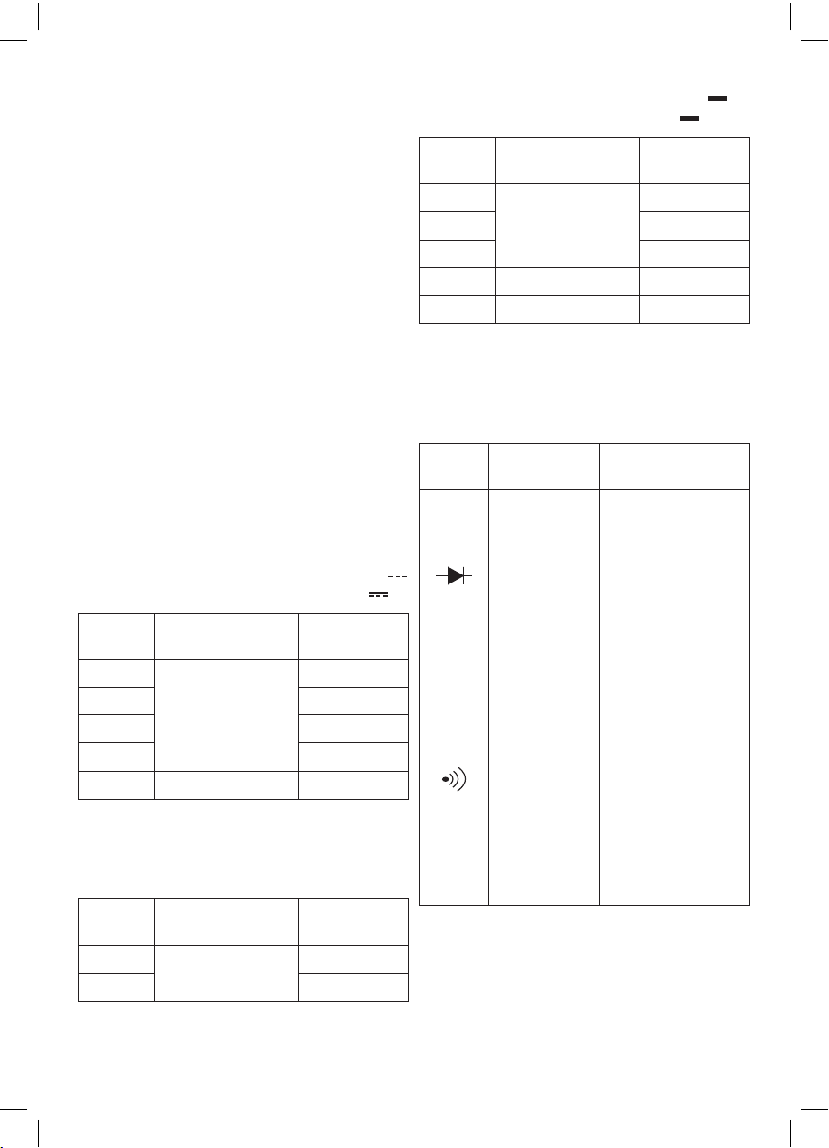
MISURAZIONE DELLA CORRENTE CONTINUA
FINO A 10A
Questo tester non è progettato per effettuare
misure di corrente alternata.
Attenzione! Con la presa 10A(5) non supe-
rare mai il limite di 10A
1) Collegate la sonda rossa alla presa ‘10A’(5)
e quella nera alla presa “COM”(3).
2) Portate il selettore (2) nel settore “10A”.
3) Procedere alla misura.
Attenzione la presa è protetta da un fusibile di
protezione che potrebbe intervenire in caso di
superamento dei 10A.
MISURAZIONE RESISTENZA
1) Collegate la sonda rossa alla presa (4) “VΩ”
e quella nera alla presa COM (3).
2) Portate il selettore (2) nel settore Ω nella
scala voluta
3) Procedere alla misura.
ATTENZIONE: la misura di resistenza su un
circuito dovrà essere effettuata sempre in
assenza di energia. Non collegare mai i puntali
a sorgenti di tensione, oltre che pericoloso, lo
strumento può essere danneggiato.
TEST DI CONTINUITÀ
ATTENZIONE: il circuito su cui si intende
eseguire il test non deve essere in tensione per
non provocare gravi danni allo strumento.
1) Collegate la sonda rossa alla presa (4) “VΩ”
e quella nera alla presa COM (3).
2) Portate il selettore (2) nel settore DIODO
, CICALINA
3) Procedere alla misura.
In caso sia presente continuità nel circuito
avvertirete un suono in concomitanza con l’ac-
censione della spia LED(6).
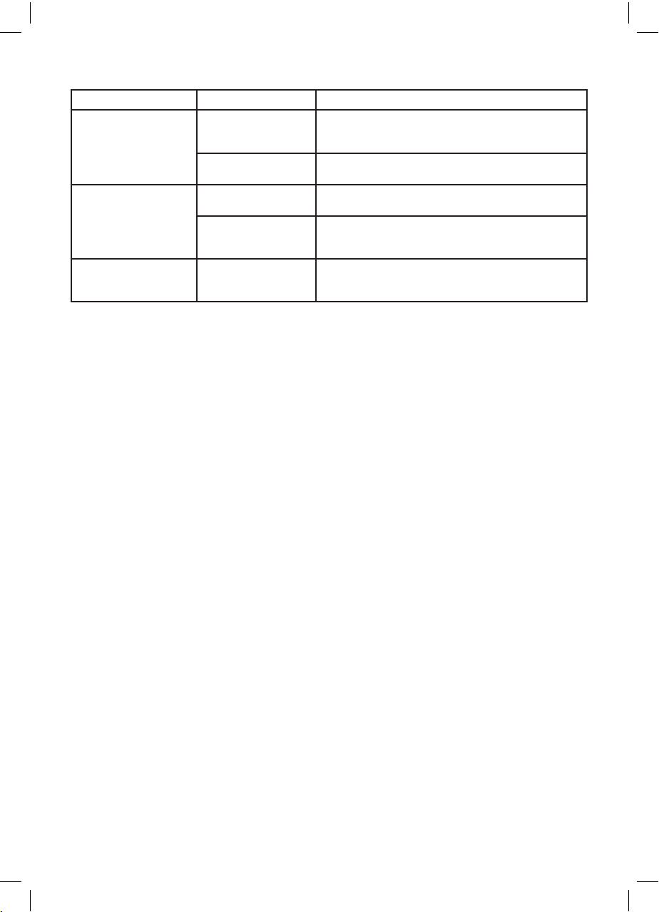
TEST DIODI
ATTENZIONE: il circuito su cui si intende
eseguire il test diodi non deve essere in tensione
per non provocare gravi danni allo strumento.
1) Collegate la sonda rossa alla presa (4) “VΩ”
e quella nera alla presa COM (3).
2) Portate il selettore (2) nel settore DIODO
, CICALINA
3) Procedere con la misura; collegare i puntali
ai poli del diodo da testare. Leggete la caduta
di tensione direttamente sul display in mV. Se
la connessione é invertita, o la giunzione del
diodo aperta, il display mostrerà il valore “I”.
GENERATORE DI ONDA QUADRA A 50Hz
1) Collegate la sonda rossa alla presa (4) “VΩ”
e quella nera alla presa “COM” (3).
2) Portate il selettore (2) nel settore ONDA
QUADRA .
Attenzione questa è una uscita di segnale. Non
è presente una protezione per il corto circuito.
SOSTITUZIONE BATTERIE
Assicurarsi che durante l’installazione della
batteria l’apparecchio sia spento (selettore
funzioni (2) in posizione OFF). Ciò evita danni
al multimetro in caso di errato collegamento
della batteria.
Sostituite la batterie quando il simbolo
batteria appare sul display. Per la sostitu-
zione seguire le indicazioni seguenti:
- rimuovere il guscio protettivo (7)
- con l’utilizzo di un cacciavite rimuovere lo
sportello vano batteria posteriore (8).
- togliete le batteria e sostituitela.
- chiudete il coperchio dell’alloggiamento e
riavvitate le viti.
- montate il guscio protettivo.
SOSTITUZIONE FUSIBILE
La presa 10A (5) è protetta contro i sovraccarichi
da un fusibile (15) interno all’apparecchio.
In caso di intervento, ridurre la corrente e so-
stituire il fusibile con uno di pari caratteristiche
(non fornito).
Per la sostituzione seguire le indicazioni seguenti:
- rimuovere il guscio protettivo (7)
- con l’utilizzo di un cacciavite rimuovere il
coperchio posteriore (8)
- togliete il fusibile (11) guasto e sostituitelo con
uno di pari valore
- chiudete il coperchio dell’alloggiamento e
riavvitate le viti.
- montate il guscio protettivo.