Caliber SCFGPA User manual

SCFGPA Target System Help Manual-V1.2
This manual is work-in-progress. It contains additional information not found in the
CR-2TL Operations Manual. Corrections and additions would be appreciated.
Items marked in RED are precautions or corrections to the CR-2TL Manual.
Contents
1 - Preventive Maintenance
PM every month (steps 1-4)
PM every six months (steps 5 and 6)
2 –Troubleshooting
2.1 Troubleshooting Table
2.2 Popup--Bus Short Error
2.3 Popup--Lane Home Switch Error
2.4 Popup--Local Travel Error
2.5 Popup--Communications Error
2.6 Resetting the Drive Unit
2.7 Resetting the Master CPU error
2.8 Resetting Drills hang-ups
2.9 Lights and Strobes
3 –Repair and Replace
3.1 Replacing Bus Bars
3.2 Replacing track sections
3.3 Replacing aircraft cables
3.4 Adjusting aircraft cable spring tension
4 –Hardware and electronics
4.1 Voltages
4.2 Cables
4.3 Drive Control Unit
4.4 Master Control Unit
4.6 Target Carrier Track
4.7 Shooting Booths
4.8 Spares
5 –Local Control Screens
5.1 Startup Screen
5.1a Reference Carrier button
5.2 Main Menu
5.3 Basic Mode
5.4 Manual
5.5 Drills
5.6 Random
5.7 Scenarios
5.8 Lights
5.9 Maint
5.9a Lane Setup
6 –Master Control Screens
6.1 Login Screen
6.2 Main Menu
6.3 Manual
6.4 Auto Control
6.5 Program Scenarios
6.6 Booth Control
6.7 Lights Control
6.8 Maintenance
6.8a Password
6.8b Range Setup
7 –Warning Popups
7.1 Cease Fire
7.2 Assistance Required
7.3 Referencing the Target Carrier
7.4 Warning Invalid Distance
8 –Schematics
8.1 System
8.2 Aircraft Cable control
8.3 Target Carrier control
Ray 732-763-2188 senpercon@gmail.com

1. Preventive Maintenance
1-Inspect Shooting Booths (each month)
Inspect each booth for broken, worn or bent parts and weakened areas.
Inspect each target carrier and track above the booth for damage, missing nuts,
bolts and for casings that may have landed there.
2-Inspect Cables (each month)
Inspect the aircraft cables for signs of fraying or damage. The cable lies on the
top of the track and on the lower right hand side flange of the track (the I beam).
3-Inspect Tracks (each month)
Check the target track to clear any debris from the top of the track and the sides of the
track. Wipe off top of track if needed. Run all targets to 75 feet and look and listen for
unusual sounds, vibrations, etc. The Carrier should not sound like a train coming down the
track. Check that the bottom joints of the track are level. When the target carrier moves
down the track, there should be little up/down or side to side movement. Compare with
other lanes with issues any different from the ones without issues. It is important that the
bottom of the track is level at each joint. This reduces wear on the Target Carrier wheels
and reduces noise and rocking motion as the target carrier moves down range and back.
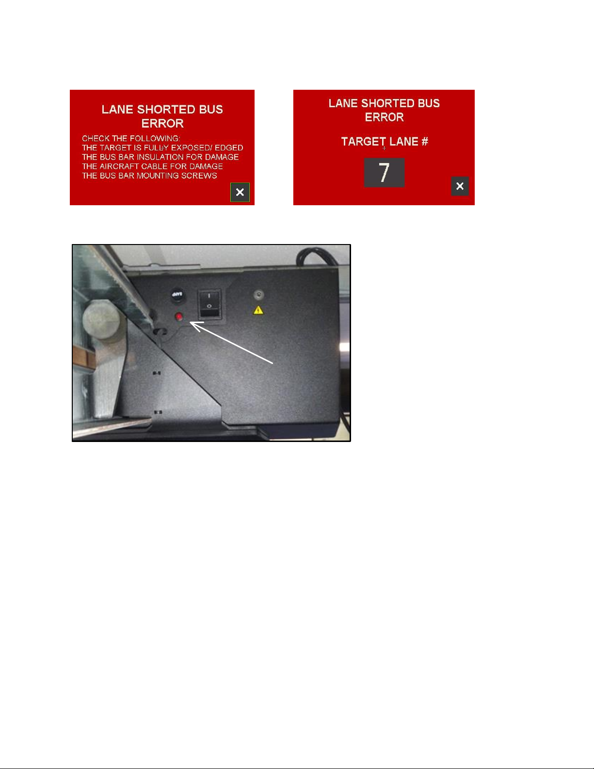
4-Inspect Bus Bars (each month)
Check the Bus Bar and the insulator between the track and the Bus Bar for damage. Check
Bus Bar screws if damaged or missing. Check if aircraft cable is frayed and might touch the
Bus Bar. Make sure that the joints on the copper bus bar are flat between the 2 pieces.
Check if any of the screws holding the bus bar on to the track protrude through the bus bar
and stick out from the bus bar. Check for bent bus bars.
5-Clean Tracks and Bus Bars (each January and June)
Make sure all targets are at home position before cleaning. Turn power off then use D-
Lead cleaner on the Tracks. Use alcohol on the Bus Bars. Make sure everything dries. After
cleaning, turn power back on. Run the target carrier out and check that the lights work and
the target turns.
6-Check Spring Tension (each January and June)
Check spring tension of the aircraft cable that it is at the correct length, adjust if necessary.
See Section 3.4 Adjusting aircraft cable spring tension (See additional instructions on
Page 21 of the Caliber Target Manual).

2. Troubleshooting
2.1 Troubleshooting Table
The Caliber Target System performs two separate functions or sub-systems:
1. Moving the target carrier up and down the range
2. Turning the target and turning on the lights
In most cases, a problem with one sub-system should not affect the other.
Note: The first 4 symptoms describe popups that would appear on the local Screen. If you
don’t see a popup, it was probably cleared by someone but the problem may still exist.
Symptom
Possible cause
Section
The target will not turn and may
be stuck at an odd angle and the
target carrier lights will not go on
Damaged Bus Bar insulator
or Bus screws. Frayed
aircraft cable shorting to
the Bus Bar. Dirt buildup
on the Bus. Short inside the
Target Carrier.
2.2 Bus Short Error (popup)
The Carrier has stalled on the
dead stop at the drive unit
Home switch problem
2.3 Lane Home Switch Error
(popup)
The target carrier cannot reach
the position it was commanded to
go to
Damaged track
Frayed aircraft cable
Bad encoder
2.4 Local Travel Error (popup)
Master Control lost contact with
one of the Lanes
Unplugged or bad Cat6
cable
2.5 Communications Error (Master
Screen only) (popup)
Target does not respond to move
commands
Motor VFD in error
Bad Drive Motor
Aircraft cable bad
2.6 Resetting the Drive Unit
Targets become unresponsive
from the Master Control Screen
only
Master Control CPU error
2.7 Resetting the Master CPU
Targets become unresponsive
from action shooting.
Uncompleted Drills
2.8 Resetting Drills hang-ups
Problems with lights and strobes
Dirty bus bar
User misunderstanding
2.9 Lights and strobes

2.2 Bus Short Error
Local Screen –Page 59
Master Screen –Page 59
Back of Drive Unit
Bus short LED
The Bus Short error will appear
when the bus bar becomes in
direct contact with the track or
some other conductive object.
The Bus Short LED (under the fuse)
will come on and the Lane Shorted
Bus Error popup will appear.
The target will not turn and the
target carrier lights will not work.
This picture is different in the
CR-2TL Target Manual
Bus Shorts can happen in a number of ways.
1. The target doesn't complete a turn and is not fully exposed or edged.
2. The Target Carrier may have a short inside.
2. The insulator between the track and bus bar gets shot and damaged.
3. The bus bar nylon washers and screws get shot and damaged.
4. The aircraft cable frays and touches the bus bar screws.
Finding the short
Step 1
If the Bus Short LED is NOT on, clear the Popup. If the target moves and lights work, log the
event as an intermittent short. If the Bus Short LED is ON, go to Step 2.

2.2 Bus Short Error, continued
Step 2
Corrective action (from page 59 of the CR-2TL Manual)
• Make sure the target is fully exposed or edged, if not, move it manually
• Visually inspect the bus bar insulation for signs of damage
• Visually inspect the bus bar nylon washers and screws for signs of damage
• Visually inspect the aircraft cable for signs of fraying
• Visually inspect the target carrier for signs of damage
• Visually inspect the gap between bus bars for dirt
If the fault is not found and the LED is still on go to Step 3
Step 3
Determine if the short is on the Track or in the Carrier. Place a 24" piece of electrical tape
over the bus bar and push the target carrier onto the electrical tape. If the LED is still on,
the issue is on the track, Go to Step 4. If the Bus Short LED is off, the issue is in the Target
Carrier, Go to Step 5.
Step 4 (from page 59)
1. Remove the electrical tape and switch the power off to the drive unit.
2. Go to the nearest bus bar joint at the middle of the track length and remove the brass
insert. Make sure the bus bar on the drive side is not touching the other bus bar or the
track.
3. Switch on the drive unit. If the bus short LED, is still on, the issue is from the drive unit to
the center of the track length.
4. If the bus short LED is off, the issue is from the center of the track length to the trap end
pulley.
5. Re-connect the bus bar. If the issue is closer to the drive unit, move from the center of
the track length towards the drive unit removing the brass insert at each joint until the bus
short is found.
6. If the issue is from the center of the track length to the trap end pulley move from the
center of the track length towards the trap end pulley removing the brass insert at each
joint until the bus short is found. Typically most bus shorts are located towards the trap
end pulley.

2.2 Bus Short Error, continued
Step 5
Troubleshooting inside the Carrier
1. Switch the power off to the drive unit.
2. Make sure the target is fully exposed or edged, if not, move it manually
3. Remove left side of the Target Carrier.
Check for damage to the
power pick-ups. Check
for a trapped case that
may be shorting the
carrier to the Bus. You
may need to stick your
hand inside and feel for a
loose case.
4. Remove right side of the Target Carrier.
Make sure the aircraft
cable is not damaged and
the “tail” wrapped around
the ratchet is clear of the
Bus Bar screws.
5. If the short was found, remove the electrical tape and turn power back on the Drive unit.
Test the carrier for movement and its lights. If the short still exists, call House and Grounds.
Important notice about the copper Bus Bar mounting screws:
Only tighten the bus bar screws by hand using an Allen key and do not use impact or
torque drill as these can strip the thread in the copper. Tighten the screws until the flange
of the nylon shoulder washer just begins to compress under the head of the screw.
Remove only these 2 screws
Use 5/32 Allen drive
Tensioning spring is behind the black Target Carrier cover.
Remove only these 2 screws
Use 5/32 Allen drive

2.3 Lane Home Switch Error
Local Screen –Page 57
Master Screen –Page 57
The lane home switch error is displayed if the target carrier has entered its ramp down
deceleration when commanded to come home, and has stalled on the dead stop at the
drive unit.
Corrective action
1. Visually inspect the home switch for signs of damage. Move the target carrier
beneath the home switch and check if the light on the home switch illuminates.
2. If the home switch is illuminated when the target carrier is below the home switch,
gently rock the target carrier from side to side. The home switch LED should stay
illuminated. If it does not, move the home switch down closer to the target carrier.
3. If the home switch does not illuminate, place a metallic object (knife) near the home
switch. If the LED does not go on, check the wiring back to the Drive Unit PCB for damage.
The carrier can be manually pushed forward or pulled back by hand.
The home sensor will activate through the entire width (about 18”) of the carrier.
The top of the carrier is metal and the sensor triggers when it detects metal.

2.4 Local Travel Error
Local Screen –Page 58
Master Screen –Page 58
The lane travel error is displayed if the target carrier cannot reach the position it was
commanded to go to.
Corrective action
1. Visually inspect the track where the target carrier has stopped. The track could be
damaged. If the track is damaged, un-bolt the piece of track that is damaged and flip it
180° or replace that part of the track.
2. Try to move the target carrier by hand. If it doesn’t move freely check the target carrier
wheels for signs of damage.
3. If the track is not damaged check the aircraft cable at both ends, the trap end pulley and
at the motor pulley. Sometimes the aircraft cable will fray and get jammed. Replace the
aircraft cable. See Section 3.3 Replacing aircraft cables
4. Check the encoder is counting correctly. To check this, send the lane with the issue out
and the good lane next to it out to the same distance. Check that the “Actual Distances”
are the same or within 0.1ft. If the actual distance is zero or some large or unusual
number, replace the encoder.
2.5 Communications Error (Master Screen only)
The lane communication error will appear if one
of the lanes loses power for whatever reason.
Check that the lane being indicated is switched
on and that the CAT6 cables are plugged in fully.

2.6Resetting the Drive Unit
You may need to do a reset if the targets misbehave or are unresponsive.
Power Reset
Power Reset is used if the targets are not responding to move commands. However the
Target carrier may respond to Edge commands. The likely cause of this problem may have
been due to a power surge or a power failure.
Note: Before doing the Power Reset, remove the Drive cover and make a note of the VFD
error code displayed on the LED readout. Then power down the drive unit for 30 seconds,
reinstall the Drive cover than turn the power back on.
This picture is different in the CR-2TL Target Manual
Bus short LED, Fuse and Power
Switch are NOT part of the Cover
Mounting screws
¼”-20 x ½”
5/32 Allen Drive
Important:
Two people should perform this task. The Drive cover is a little heavy and might
fall off and drop as soon as you remove the second screw. Each person should
use a separate step ladder.

2.7Resetting the Master CPU error
If targets become unresponsive, check for the presence of the CPU error.
If error, check if any Ethernet cables have been disconnected. You will need to clear the
error. See the square error LED on red on the R04ENCPU module (picture below).
To remove the error, power off the Master Control Panel by resetting the fuse. Wait till all
the lights have gone out then switch the panel ON again.
If the error is still on the CPU you will have to reset the CPU. To do this pull the tab marked
"Pull" on the CPU module. This will lift the smoked cover up.
Beneath the cover is a 3 position switch. The switch moves horizontally and should be over
to the right.
Move the switch all the way to the left and hold it till the lights on the CPU go out.
Release the switch and it will move to the center position. When the CPU has been reset
the lights will come back on. Move the switch from the center position all the way to the
right. The switch will stay in this position. The "error" light on the CPU should now be out.
The error light on the CC-Link module will still be on. The "error" light on the CC-Link
module is normal. The system has been designed to control up to 40 lanes. Because the
network cannot see all 40 lanes it will throw up an error. This error is ignored by the CPU.
Master Control Unit showing red ERROR LED on the R04ENCPU Module

2.8Resetting Drills hang-ups
If strange things start to happen, targets are unresponsive, targets go to the wrong
position, they start to turn without being commanded, the lane or lanes need to be reset.
This can happen if the power has gone off or if someone has not stopped a mode (DRILLS,
RANDOM, or SCENNARIOS) and just returned the target to the "Home" position, the
system will try and complete the mode. It is also possible that the lane has been left during
a drill and it is trying to complete the drill before trying to do the next move.
The Drills error can be cleared from the LOCAL screen or the MASTER screen.
To reset the system on the Local lane screen, go to the "MAINT" screen and press and hold
the "MASTER DRILL RESET" button for 2-5 seconds. See Page 36 for more information.
To reset the system on the Master control Auto screen, select all the target lanes, then
press and hold the "STOP" button (there are 3 of them) for 2-5 seconds on each mode on
the "AUTO CONTROL" screen.

2.9 Lights and Strobes

3. Repairing and replacing parts
3.1 Replacing bus bars
See Bus Bar Installation on Page 13 in the CR-2TL Manual
Bus Bar Installation
The bus bar is mounted to the center of the track. An insulator separates the bus bar from
the track. The bus bar and insulator are supplied in 6ft lengths, with a 3ft length mounted
to the track start section and a custom length may have to be cut for the end section of
track. The bus bar must have electrical continuity along the whole length of the track. At
each bus bar joint a brass insert must be placed behind the bus bar and against the
insulator. The bus bar joints should be at the same position as the track joint opposite to
the bus bar. Insulated nylon washers are inserted into the center holes of the track from
the right hand side. The bus bar and insulator are mounted to the left hand side of the
track using 6 x 10-32 x ½” screws.
DO NOT USE POWER TOOLS to screw the screws in to the bus bar as it could strip the
treads in the copper bus bar.
The bus bar should be mounted to the track while it is being assembled on the ground,
with the “in fill” pieces mounted when the track is together in the air.
There is no torque setting on tightening the bus bar screws. Only tighten the bus bar
screws by hand using an Allen key and do not use impact or torque drill as these can
strip the thread in the copper. Tighten the screws until the flange of the nylon
shoulder washer begins to compress slightly under the head of the screw.

3.2 Replacing track sections
See Track Installation on Page 13 in the CR-2TL Manual
Track Installation
Each track section is symmetrical so there is no up or down side. If there is any damage to
the bottom of the track, the track can be removed and rotated 180°. There are various
track length end sections (starting at 1ft and incrementing in 1ft lengths), 3ft start section
and 6ft start sections. The left starting section of the track is 6ft long, the right starting
section is 3ft long. The remaining standard sections are 6ft long. The sections are
overlapped 3ft to provide a rigid track system. The track has square bolt holes and is
assembled using
¼”- 20 x 5/8” carriage bolts.
This makes assembling the track easier as only one 7/16” wrench or socket is required.
The carriage bolts are inserted from the Right Hand Side of the track, with the nuts
fastening on the Left Hand Side of the track. The typical method of assembling the track is
to assemble 6 pieces of track together on a work table, to make a 21ft section. This makes
hanging the track easier to work with.
Start Section 6’Sections off-set every 3’to make 21’section

3.3 Replacing aircraft cables
Before proceeding, study these 2 pages in this section and the installation of the
Aircraft Cable on Pages 20-21 in the CR-2TL Manual.
Tensioning spring is behind the black Target Carrier cover.
Remove only these 2 screws
Use 5/32 Allen drive
Cable pulley, mounted on the motor inside the
Drive Unit.
Trap end pulley.
The cable lies on the top and on the lower right hand side flange of the track.

3.3 Replacing aircraft cables, continued
Ratchet Tab
Keep finger
on it
Ratchet Bolt
7/16"
1-2 clicks=¼” 4" to4.5"
LEFT EYELET RIGHT EYELET

3.4 Adjusting aircraft cable spring tension
Tensioning spring is behind the black Target Carrier cover.
Remove only these 2 screws
Use 5/32 Allen drive
Ratchet Tab
Keep finger
on it
Ratchet Bolt
7/16"
1-2 clicks=¼” 4" to4.5"
You may work on the carrier from the firing line or move it out to inside the range under
better lighting conditions. Turn power off on the DRIVE UNIT.
Using a 7/16” wrench or socket turn the ratchet bolt clockwise to start stretching the
tensioning spring. Important, apply pressure to the ratchet tab when tightening the ratchet
to keep the cable from un-winding from the ratchet.
Each ratchet tooth equals about a 1/4” of spring stretch. Adjust spring to 4-1/4”.

4. Hardware and Electronics
4.1 Voltages
Voltages are measured at the Bus Bar
There are 2 voltage pickups (for redundancy) riding the copper bus bar.
Caliber swaps polarity to change from white light to strobe and to turn target CW/CCW.
+12vdc white carrier lights, can read with meter.
-12vdc strobe lights other than white strobe, can read with meter but have to catch the –
sign.
+24vdc for turning target one way, cannot read with ordinary meter, pulse too fast.
-24vdc for turning target the other way, cannot read with ordinary meter, pulse too fast.
-3vdc used for bus short sensing, on when at home or carrier light off, can read with meter.
4.2 Cables
Master Control Screen CAT6 cable pinout pairs 12, 36, 45, 78
Master Control Screen DC cable jack: 2.1mm ID, 5.5mm OD
Aircraft Cable 1/8" with a 7x19 construction galvanized aircraft cable, 75’ long
4.3 Drive Control Unit
AC Power:
The 10 Drive Units plug into overhead receptacles in pairs.
Their 5 Circuit Breakers are in the Ready Room.
They are numbered 33, 35, 37, 39, 41 for Drive Units 12, 34, 56, 78, 9/10.
Drive Unit components
AC Motor (for driving cable)
VFD Mitsubishi D700 for the motor
Ethernet Module FX5-CCLIEF (Intelligent device station)
CPU Module FX5UC
24VDC PS Omron s8vk-c12024
24VDC PS Omron s8vk-c06024
Cable Pulley (2 ea)
Cable 1/8" with a 7x19 construction galvanized aircraft cable, 75’ long.
Miscellaneous
Home sensor mounted over the carrier when carrier is home
AC power switch (back of Drive Unit)
AC Fuse, 8A (back of Drive Unit)
LED Bus short indicator (back of Drive Unit, below the fuse)
Drive Unit hardware
Mounting screws ¼-20 x ½” Use 5/32 Allen drive wrench

4.4 Master Control Unit
AC Power
The Master Control Unit AC is powered from CB #31
Master Control Unit
CPU Module R04EN
Ethernet Module CC-Link IE J71EN71
24VDC PS S8VK
5VDC PS R61P
4.5 Target Carrier
Target Carrier access
Right side of Carrier cover screws (2 ea.) Size ¼-28 x ½. Use 5/32 Allen wrench to
access the cable tensioning spring. Ratchet bolt wrench size 7/16”. Wrench is
used for turning ratchet to stretch the tensioning spring of the aircraft cable.
Left side of Carrier cover screws (2 ea.) Size ¼-28 x ½. Use 5/32 Allen wrench
to access to the Bus Bar voltage pickups
Target Carrier components
Tensioning ratchet assembly
Lights how many
Bus power pickups (phosphor bronze, 2 each for redundancy, left side of carrier)
Target turner (motor and a cam)
Wheels (2 rubber wheels riding left bottom flange of I beam about 5” dia)
4.6 Target Carrier Tracks
Target Carrier Track 14.5 lbs per 6 foot section
Each track section is symmetrical so there is no up or down side.
If there is any damage the bottom of the track, the track can be removed and rotated 180°.
Tracks are 2 U shaped rails bolter back-to-back to form an I beam.
Rails are .125” thick each forming a .25” thick I beam spine.
4.7 Shooting Booths
Shooting booth is 43.5” wide. Bench is 16 deep, 42 wide and 37.5 high.
Booth lights: 2 rows. Each has 4 round LED’s and 2 square LED’s. The 4 round LED’s are
white.
The 2 squares on the left are blue, the 2 squares on the right are red.
Left row: b w w w w b Right row: r w w w w r

4.8 Spares
Spare
Qty
Size/Type
Comment
Bus Bar, copper
10
6’ x 1/2” x 5/32”
10-32 threads
Bus Bar Spacer, plastic insulator
10
6’ x 5/8” x 1/16”
Bus Bar joint brass insert strips
6
6” x 1/2” x 1/64”
Bridges two Bus Bars
Bus Bar screws
many
10-32 x 1/2"
Use 1/8” Allen wrench
Nylon T-type (flanged) washers
many
For insulating Bus Bar screws
from the Track
Aircraft Cable Clamp for 1/8”
cable
1
Stainless steel, double clamp
Aircraft Cable Tensioning Spring
1
~4”
Aircraft Cable
200 feet
1/8” galvanized
7x19 construction
FUTURE
Table of contents