Ecom CP 400 User manual

CP 400/420
Bedienungsanleitung
Operating Instructions
Notice d‘utilisation

33
Contents
1. Introduction 34
1.1 Standard Equipment 34
1.2 Safety Information 34
2. Calibrator Interface 35
2.1 Calibrator Display 36
2.2 Using the Backlight 39
2.3 Using the Zero Function 39
2.4 Other Menu Controlled Functions 39
3. Measuring Pressure 42
3.1 Media Compatibility 42
3.2 Measuring Pressure with External Modules 42
4. Measuring Current 43
5. Measuring Voltage 44
6. Measuring Temperature with and RTD 44
7. Performing a Pressure Switch Test 45
8. Calibrating Transmitters 47
8.1 Using the mA Input Function 47
8.2 Calibrating a Pressure-to-Current Transmitter 47
8.3 Percent Error Function 48
9. Factory Setups 51
10. Custody Transfer / Flow Calibration 52
11. Remote Operation 52
11.1 Remote Interface 52
11.2 Setting up the RS-232 Port for Remote Control 53
11.3 Changing Between Remote and Local Operation 53
11.4 Using Commands 53
11.5 Remote Commands and Error Codes 55
11.6 Entering Commands 58
12. Specifications 62
13. Warranty 63
14. Maintenance 63
14.1 Replacing Batteries 63
14.2 Cleaning the Unit 63
15. Menu Map 64

34
1. Introduction
The CP 400/420 is designed to be a simple to use yet very versatile pressure calibrator. Its
two internal pressure sensors combined with inputs for mA, voltage, switch contacts and
an RTD probe allow the 400/420 to calibrate virtually any pressure device. An external
pressure module option allows an even wider range of pressure calibration options
including absolute and differential.
1.1 Standard Equipment
Check to see if your calibrator is complete. It should include: CP 400 or CP 420 calibrator,
instruction manual, test leads, carrying case, calibration certificate.
1.2 Safety Information
Use the calibrator only as specified in this manual, otherwise injury and damage to
the calibrator may occur.
Warning
To avoid possible electric shock or personal injury:
- Do not apply more than the rated voltage. See specifications for supported ranges.
- Follow all equipment safety procedures.
- Never touch the probe to a voltage source when the test leads are plugged into the
current terminals.
- Do not use the calibrator if it is damaged. Before you use the calibrator, inspect the
case. Look for cracks or missing plastic. Pay particular attention to the insulation
surrounding the connectors.
- Select the proper function and range for your measurement.
- Make sure the battery cover is closed and latched before you operate the calibrator.
- Remove test leads from the calibrator before you open the battery door.
- Inspect the test leads for damaged insulation or exposed metal. Check test leads
continuity. Replace damaged test leads before you use the calibrator.
- When using the probes, keep your fingers away from the probe contacts.
Keep your fingers behind the finger guards on the probes.
- Connect the common test lead before you connect the live test lead.
When you disconnect test leads, disconnect the live test lead first.
- Do not use the calibrator if it operates abnormally. Protection may be impaired.
When in doubt, have the calibrator serviced.
- Do not operate the calibrator around explosive gas, vapor, or dust.
- When measuring pressure, make sure the process pressure line is shut off and
depressurized before you connect it or disconnect it from the pressure module.
- Disconnect test leads before changing to another measure or source function.
When servicing the calibrator, use only specified replacement parts.
- To avoid false readings, which could lead to possible electric shock or personal injury,
replace the battery as soon as the battery indicator appears.
Caution
To avoid possible damage to calibrator or to equipment under test:
- Use the proper jacks, function, and range for your measurement or sourcing application.

35
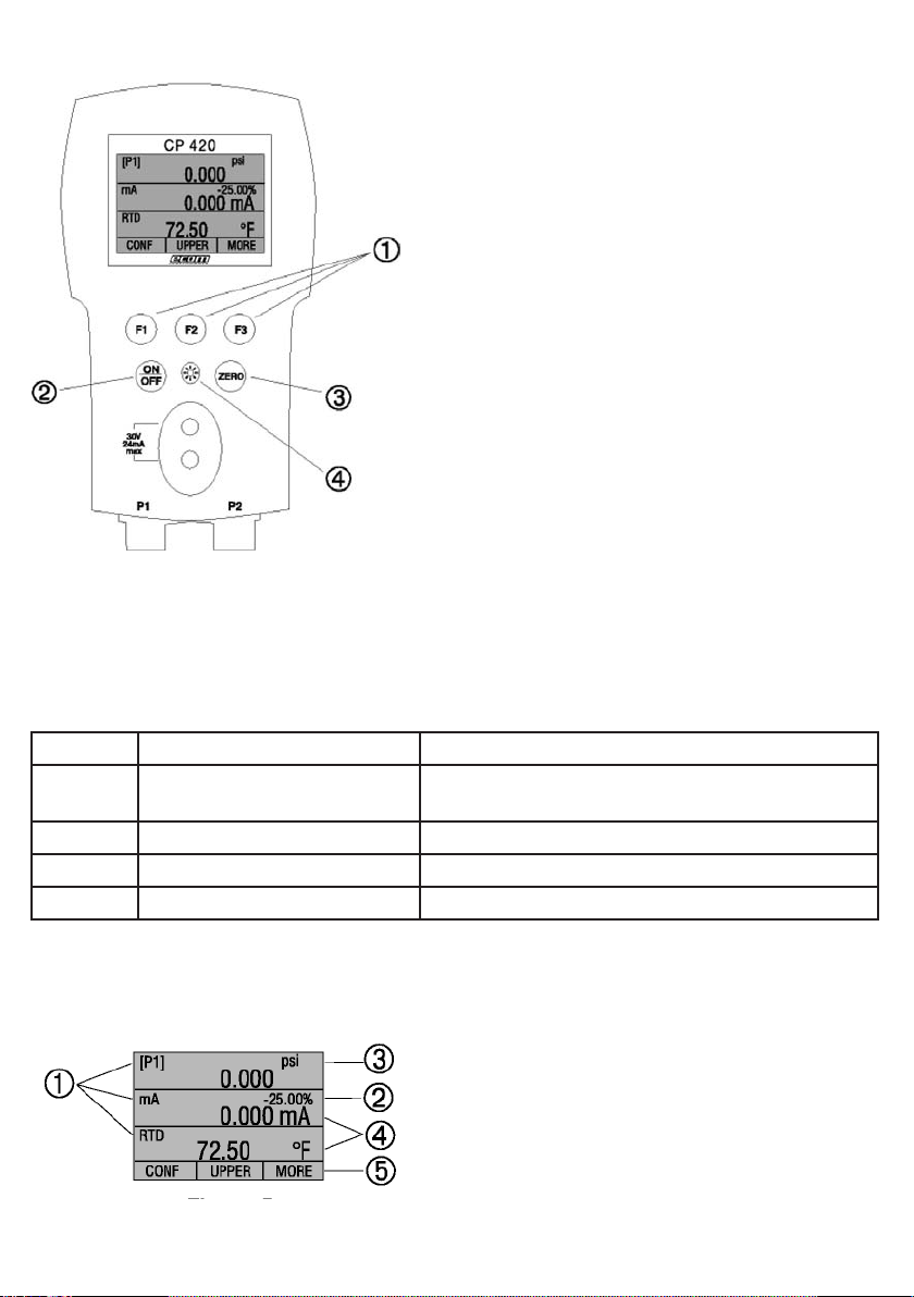
2. Calibrator Interface
Figure 1 shows the location of the process measurement inputs, while table 1 describes their use.
Figure 1: Pressure Measurement Inputs Side View
Table 1: Process Measurement Inputs
No. Name Description
1, 2 Input Terminals These terminal are used to measure current, voltage and
a contact closure for switch test.
3 P1 Pressure Port This is the connection for the internal sensor P1
4 P2 Pressure Port This is the connection for the internal sensor P2
5 RTD Probe Connector This connector is where the RTD probe is plugged in.
6 Serial Interface This is used to interface to optional external modules.
36
Figure 2 shows the location of the keys. Table 2 describes the function of each key.
Figure 2: Keypad
Table 2: Key Functions
No. Name Description
1 Function Keys These keys are used in various ways, primarily
to configure the calibrator
2 ON/OFF Key This key is used to turn the calibrator on and off
3 ZERO Key This key is used to zero pressure measurements
4 Backlight Key This key is used to turn the backlight on and off
2.1 Calibrator Display
The Calibrator Display consists of two regions: The menu bar (located along the bottom
of the screen) is used to access a menu system. The main display (the rest) consists of
up to three process measurement sub-regions.
These sub-regions will henceforth be referred to as the
UPPER, MIDDLE and LOWER displays. Figure 3 shows
the location of the different display fields while table 3
describes them.
Figure 3: Display
37
Table 3: Display Functions
No. Name Description
1 Primary Parameters Indicates what is being measured
2 Span Indicator Indicates the percent of the 4 to 20 mA span.
(For mA and mA Loop functions only)
3 Pressure Units Indicates one of 17 pressure units available for display
4 Units ndicates the unit of measure for the display
2.1.1 Main Menu Functionality
There are three options on the Main Menu, CONFIG, {current display} and MORE. The
Main Menu is home for the menu display.
2.1.1.1 Setting the Current Display
The current display is indicated by the center option on the Main Menu, pressing the F2
key will toggle the current display.
2.1.1.2 Setting Current Display Parameters
To set the parameters of the current display use the CONFIG option to get to the Display
Configuration Menu.
Here the SELECT option will toggle through the choices for each parameter. The first
parameter is MODE. Since voltage, current and switch test modes all use the same
jacks, two of these functions cannot be used concurrently. The ability to select certain
functions is limited based on what is already selected in another active display. The
NEXT option is used to change to the second parameter. Only RTD and Pressure modes
have a second parameter, RTDs can be read in Celsius or Fahrenheit and Pressures can
be read in 13 engineering units.
With a single display the following modes are available:
P[1] = Pressure on left side sensor.
P[2] = Pressure on right side sensor.
[EXT] = Pressure with external pressure module.
P[1] ST = Switch Test with left side sensor.
P[2] ST = Switch Test with right side sensor.
[EXT] ST = Switch Test with external pressure module.
mA = Milliamps measure without loop power.
mA LOOP = Milliamps measure with loop power.
VOLTS = Voltage Measure.
RTD = RTD Temperature Measurement (if a probe is connected).
The following table shows which functions are available concurrently.
An X in a column indicates that the mode in the current display will not be available for
selection if the mode in that row is in use in any other active display.
38
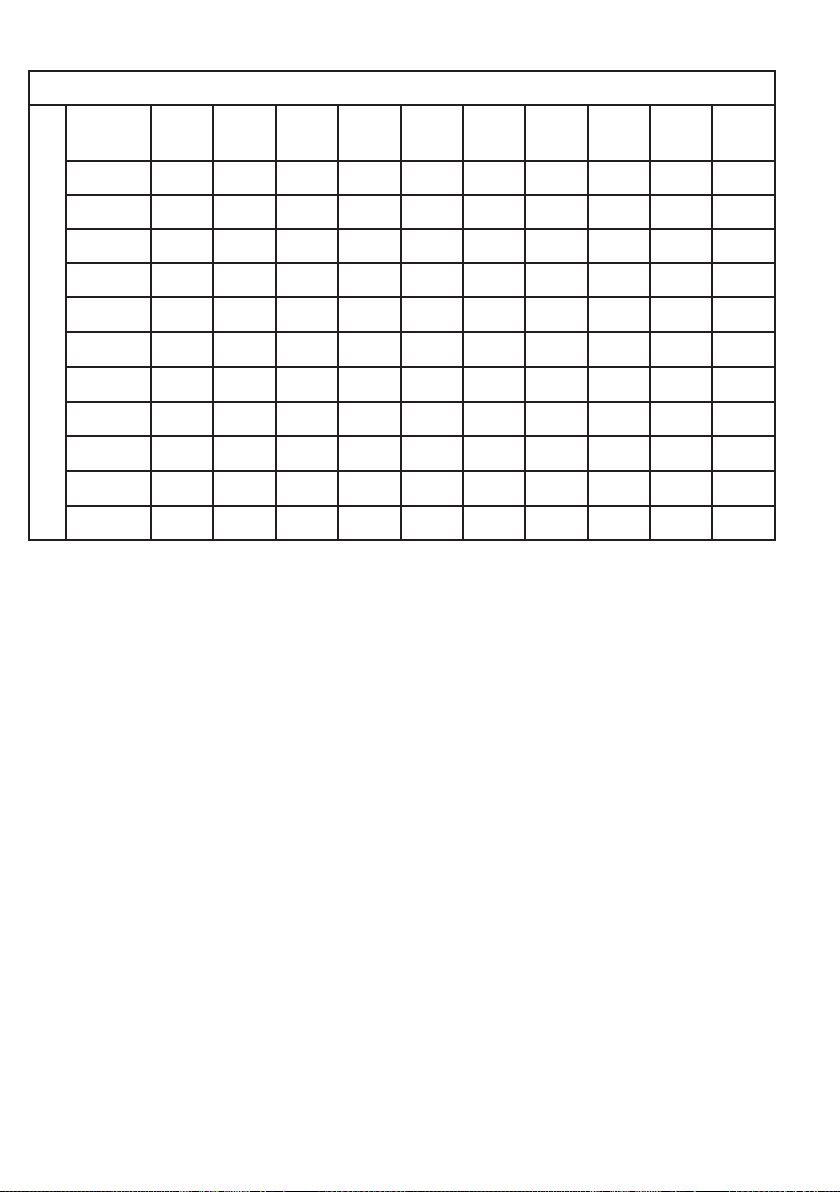
Table 4: Mode Concurrency
CURRENT DISPLAY
OTHER DISPLAY
P(1) P(2) (EXIT) P(1)
ST
P(2)
ST
(EXIT) mA mA
Loop
Volt RTD
P(1)
P(2)
(EXIT)
P(1)
P(1)ST XXXXXX
P(2)ST XXXXXX
(EXIT) XXXXXX
mA XXX XX
mALoop XXXX X
Volt XXXXX
RTD
2.1.1.3 Accessing Other Menus
Use the MORE option on the Main Menu to access the other menu functions.
(See page 64, Menu Map)

39
2.2 Using the Backlight
The backlight is controlled by the dedicated backlight key. It toggles on and off when the
key is pressed; this is one of the few functions that cannot be controlled by the serial
interface.
2.3 Using the Zero Function
When the ZERO_KEY is pressed, the calibrator will zero the current display if a pressure
mode is selected, and the pressure is within the zero limit.
2.3.1 Internal Sensor and Pressure Module (non-absolute)
When a sensor or module is selected on the current display and the ZERO_KEY is
pressed the calibrator subtracts the current reading from the output.
2.3.2 Absolute Pressure Module
When an absolute pressure module is selected on the current display and the ZERO_KEY
is pressed the calibrator prompts the user to enter the barometric reference pressure.
This is done using the arrow keys (F2 and F3 Keys).
2.4 Other Menu Controlled Functions
There are eight ‘sub-main’ menus that can be accessed through the MORE option of the
Main Menu. A ‘sub-main’ menu contains three options. The first option is unique to the
function. The second and third options of a ‘sub-main’ menu are always the same. The
NEXT option leads to the next ‘sub-main’ menu and the DONE option returns home . For
the last ‘sub-main’ menu the NEXT option wraps around to home. See Page 64 for a
detailed mapping of the menu structure.
A note on naming convention:
If a ‘sub-main’ menu has subordinate menus, it will henceforth be referred to as
{function} Main Menu. E.g. the display contrast sub-main menu will be called the
Contrast Main Menu. If not it will be called the {function} menu.
2.4.1 Setting the Contrast
From the Contrast Main Menu choose the CONTRAST option to access the Contrast
Adjustment Menu.
Use the arrow keys to adjust the display contrast to the desired level and then use the
CONTRAST DONE option to return home.

40
2.4.2 Locking and Unlocking Configurations
Use the LOCK CFG or UNLOCK CFG option of the Configuration Lock Menu to lock or
unlock the display configuration.
When the LOCK CFG option is chosen the menu display returns home and the CONFIG
option on the Main Menu indicates that it is locked. Also all menus are locked out with
the exception of the Contrast Adjustment menus and the Configuration Lock Menu.
When the UNLOCK CFG option is chosen the configuration is unlocked and the menu
display continues to the next sub-main menu.
2.4.3 Saving and Recalling Setups
The calibrator will automatically save the current set-up for recall at power-up.
Additionally 5 set-ups can be accessed through the SETUPS menu.
Select the SETUPS option from the Setups Main Menu.
Choose SAVE to save a set-up , RECALL to recall the set-up, or DONE to do nothing and
return home.
If SAVE or RECALL is selected use the arrow keys to select the set-up location. Then use
the save option to store the current set-up into the selected location or the recall option to
recall the set-up stored in the selected location. The display menu will automatically go
home.
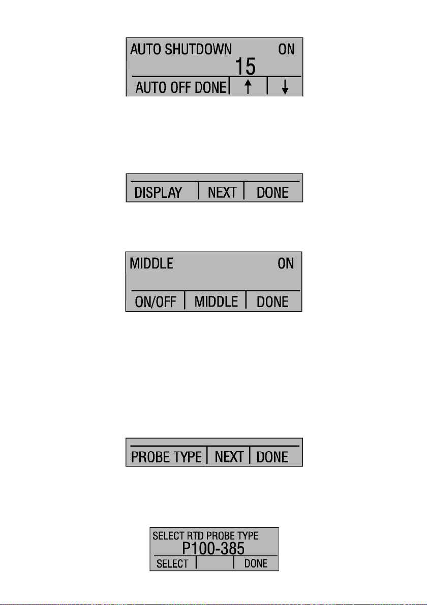
2.4.4 Setting AutoShut-off Parameters
The calibrator can be set to automatically shut-off after a selected number of minutes; this
function can also be disabled. To set the auto shut off parameters select the AUTO OFF
option on the Auto Shut Off Main Menu.
41
Use the arrow keys to select the number of minutes before the calibrator turns off or
disable auto shut-off by scrolling all the way down.
Use the AUTO OFF DONE option to set the parameters and return home. The auto shut
off time is reset whenever a key is pressed.
2.4.5 Activating and Deactivating a Display
Use the DISPLAY option on the Display Selection Main Menu to access the Display
Activation Menu.
The {function} option can be used to select which display to act upon. The ON/OFF
option turns the selected display on or off. The selected display and current on/off state
are displayed in the lower display.
Use the DONE option to save the changes and return home. When a display is
deactivated its configuration is retained. When the display is activated its configuration is
checked against the configurations of the other currently active displays, if the
configurations are in conflict the recalled display’s configuration is modified to avoid the
conflict. If all three displays are deactivated the LOWER display will come on
automatically
2.4.6 Setting the RTD probe type
Use the PROBE TYPE option of the RTD Probe Type main menu to access the RTD
Probe selection menu.
There are four probe types to select from P100-385, P100-392, P100-JIS and CUSTOM.
Use the SELECT option to select the desired probe type and the DONE option to store
the change and return home.
Note: The default probe type is PT100-385.

42
3. Measuring Pressure
To measure pressure, connect the calibrator using an appropriate fitting. Choose a
pressure setting for the display being used. The calibrator is equipped with two internal
sensors and many optional external sensors (EPMs) are available. Be sure to choose the
sensor based on working pressures and accuracy.
Figure 5
Use the (ZERO) key to zero the pressure sensor when vented to atmospheric pressure.
Important NOTE: To ensure accuracy of the calibrator it is critical to zero the calibrator
before a device is calibrated.
3.1 Media Compatibility
The calibrator utilizes a media isolated sensor to prevent sensor contamination.
Whenever possible clean, dry air is the media of choice. If that is not always possible,
make sure that the media is compatible with Nickel Plated Brass and 316 Stainless Steel.
3.2 Measuring Pressure with External Modules
The calibrator provides a digital interface to External Pressure Modules. These modules
are available in various ranges and types including gauge, vacuum, differential and
absolute. The modules work seamlessly with the calibrator. Simply plug them into the
interface and select [EXT] (external sensor). Since the interface between the calibrator
and the module is digital all the accuracy and display resolution is derived from the
module.

43
Figure 6
4. Measuring Current
To measure current use the input terminals in the front of the calibrator. Select the mA
function on one of the displays. Current is measured in mA and percentage of range.
The range on the calibrator is set to 0% at 4 mA and 100% at 20 mA.
For example:
If the current measured is displayed as 75% then the mA value is 16 mA.
Figure 7
Model BPPA
Pressure Module
Adapter
Pressure Module
Device
under
Test
4 to 20mA
P1 P2
30V
24mA
max
44
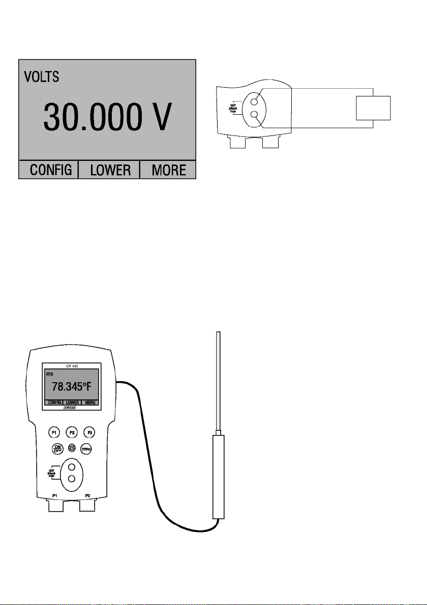
5. Measuring Voltage
To measure voltage use the input terminals in the front of the calibrator. Select the Volts
function on one of the displays. The calibrator can measure up to 30V.
Figure 8
6. Measuring Temperature with and RTD
To measure temperature using an RTD probe you must select the RTD function on one of
the displays. Make sure the proper probe type is selected. There are 4 probe types
supported, P100-385, P100-392, P100-JIS and CUSTOM.
Note: The factory default type is PT100-385 so if the CP 400/420 is being used with the ecom
Model LPT100A probe you do not have to set the probe type. Simply plug the probe into
the CP 400/420 and configure the display to read temperature.
If a custom probe is being used, the entering of R0 and coefficients is handled through
the serial interface (see section 11).
Figure 9
Device
under
Test
Up to
30V
P1 P2
RTD Probe
45
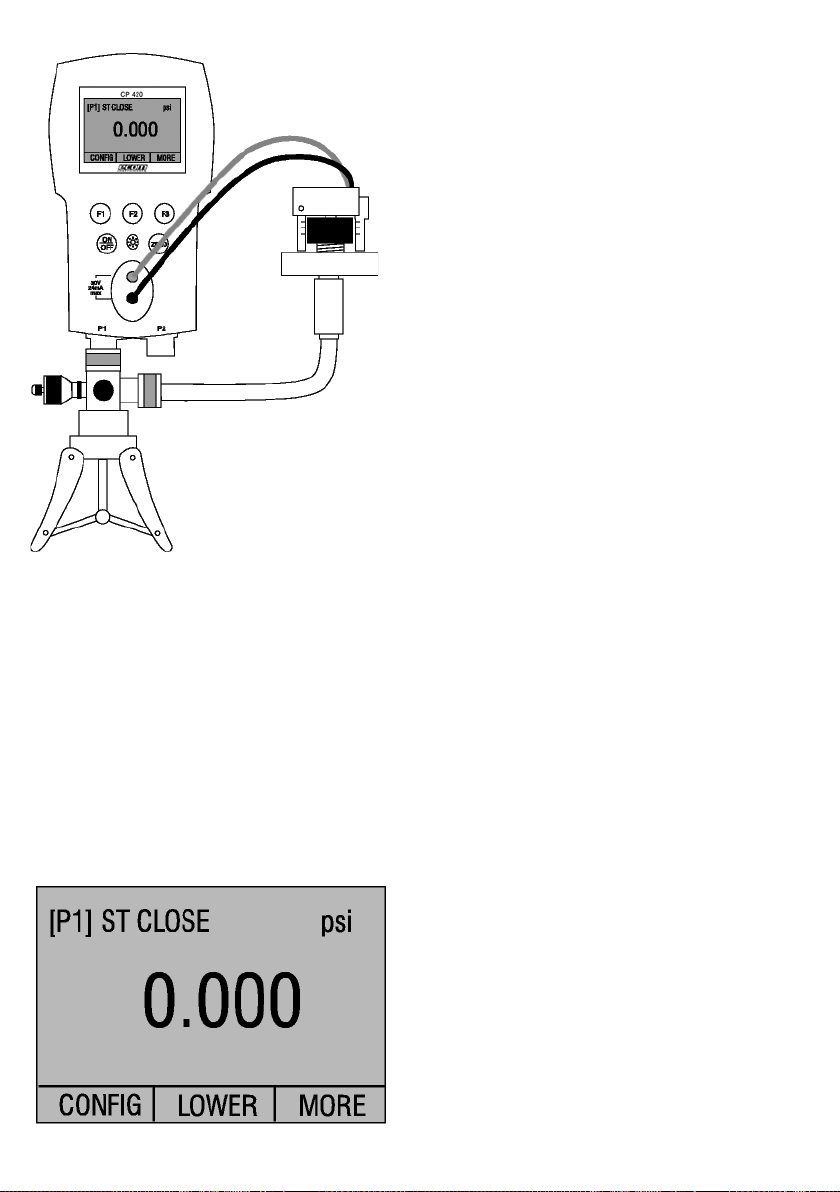
7. Performing a Pressure Switch Test
Figure 10
To perform a switch test, follow these steps:
1. Change the setup to Setup 4 (default switch test).
Setup 4: The upper display is set to [P1] ST, all other displays are off.
Important NOTE:
The pressure Switch Test can be performed with the following functions[P1] ST, [P2] ST, or EXT ST.
2. Connect the calibrator to the switch using the pressure switch terminals. The polarity
of the terminals does not matter. Then connect the pump to the calibrator and the
pressure switch.
3. Make sure the vent on the pump is open. Zero the calibrator if necessary.
Close the vent after zeroing the calibrator.
4. The top of the display will read “CLOSE”.
Pressure switch under test
46
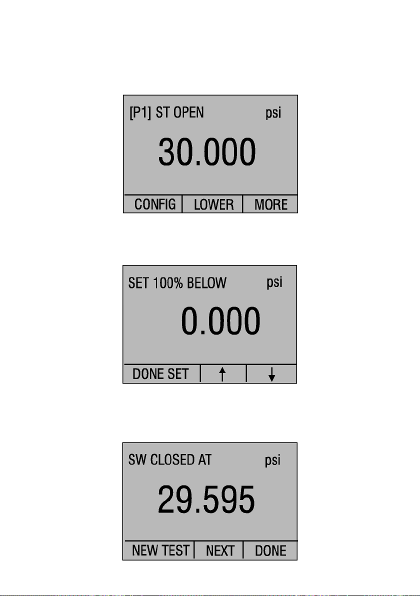
5. Apply pressure with the pump slowly until the switch opens.
Important NOTE: In the switch test mode the display update rate is increased to help
capture changing pressure inputs. Even with this enhanced sample rate pressurizing the
device under test should be done slowly to ensure accurate readings.
6. Once the switch is open, “OPEN” will be displayed, bleed the pump slowly until the
pressure switch closes.
7. At the top of the display it will now read, “SW OPENED AT” and give you the
pressure that the switch opened at.
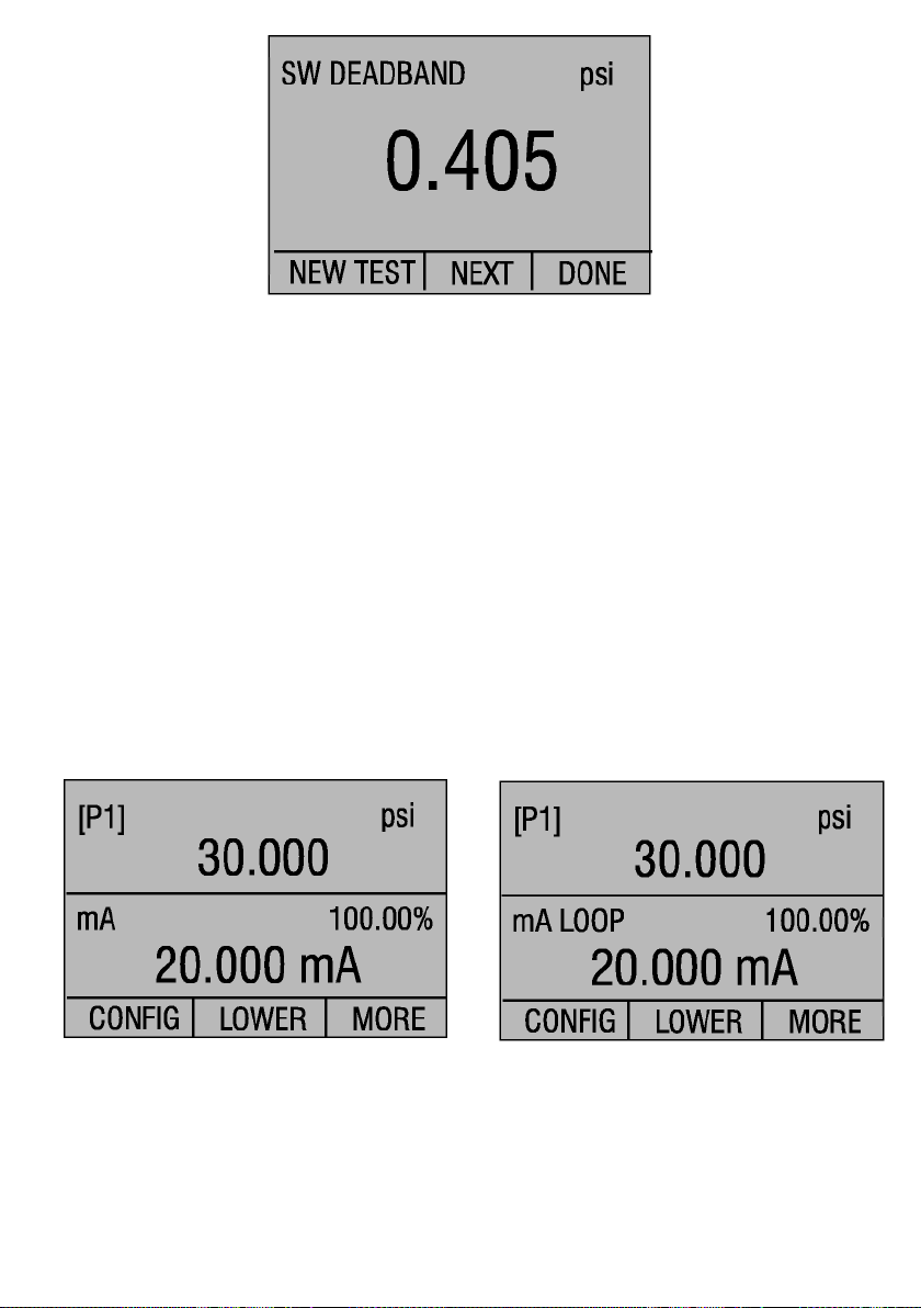
8. Press the “NEXT” option to view when the switch closed, and the dead band.
47
9. Press the “NEW TEST” option to clear the data and perform another test.
10. Press the “DONE” option to end the test and return to the standard pressure setting.
Example:
[P1] ST will return to [P1].
Important NOTE: The previous example uses a normally closed switch.
The basic procedure is still the same for a normally open switch, the display will just read “OPEN”
instead of “CLOSE”.
8. Calibrating Transmitters
8.1 Using the mA Input Function
The mA input function allows the user to read back the 4-20 mA output from the device
being calibrated. This can be done in one of two ways.
1) Passively - Where the device under test directly generates 4-20 mA and can be read by
the calibrator.
2) Actively – Where the calibrator supplies 24 VDC loop power to the device under test to
power the device while reading the resulting 4-20 mA signal.
1) 2)
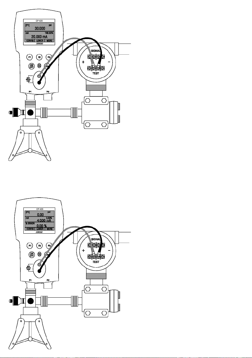
8.2 Calibrating a Pressure-to-Current Transmitter
To calibrate a pressure-to-current transmitter (P/I), perform the following steps:
1. Connect the calibrator and the pump to the transmitter.
2. Apply pressure with the pump.
3. Measure the current output of the transmitter.
4. Ensure the reading is correct. If not, adjust the transmitter as necessary.
48
Figure 11.
8.3 Percent Error Function
The calibrator features a unique function which can calculate pressure vs. milliamp error
as a percentage of the 4 to 20 mA loop span. The percent error mode uses all 3 screens
and has a unique menu structure. It simultaneously displays pressure, mA and percent
error.
Figure 12.
49
Example:
Suppose a pressure transmitter under test is 30 psi (2 Bar) Full Scale and outputs a corresponding 4
to 20 mA signal. The user can program in a 0 to 30 psi pressure span into the calibrator and the
calibrator will calculate and display the deviation or % Error from the expected 4 to 20 mA output.
This eliminates the need for manual calculations and also helps if it becomes difficult to set an exact
pressure with an external pump.
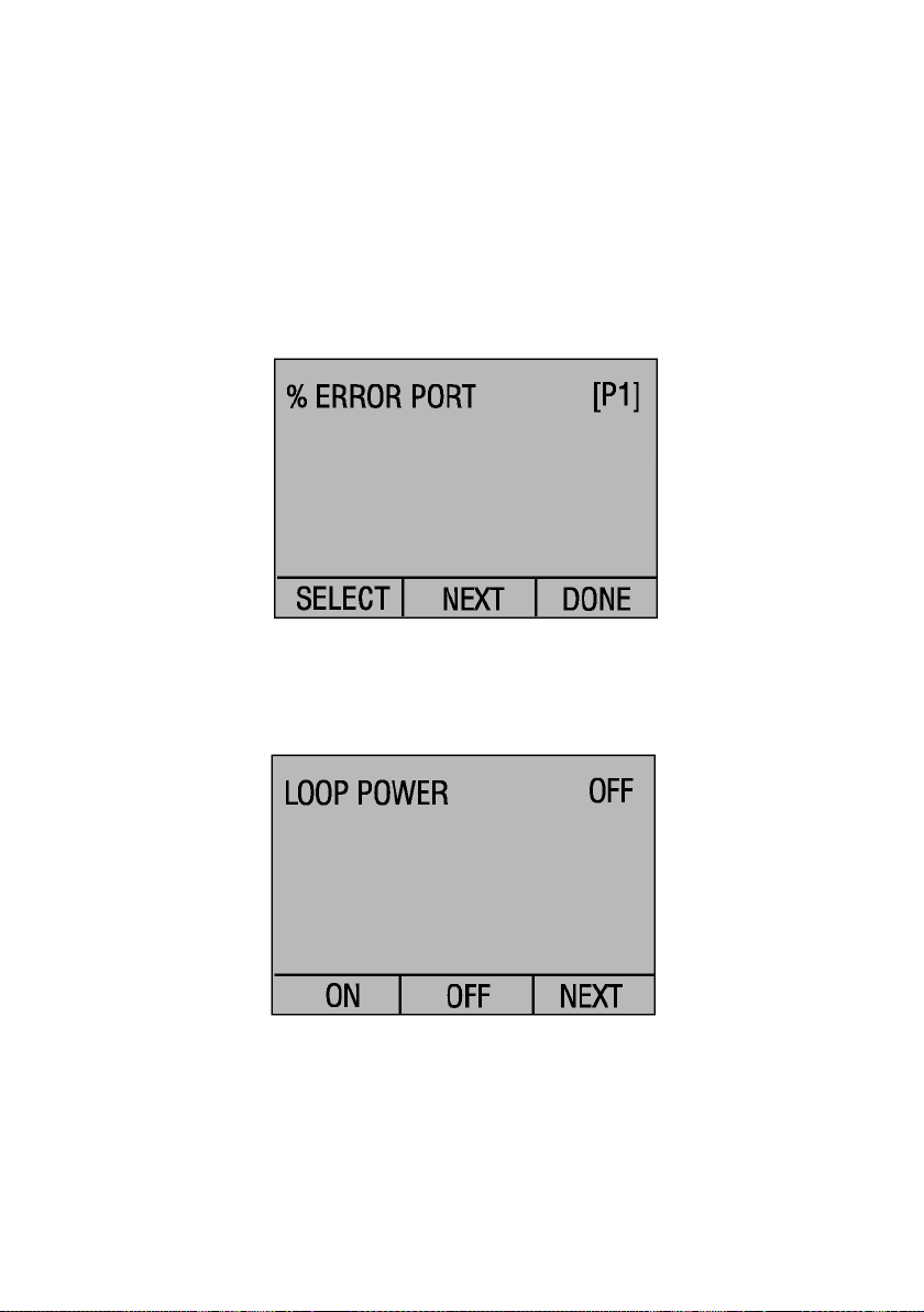
To use the %ERROR function proceed as follows:
1. With the calibrator turned on and operating press the F3 key to activate the MORE
menu option. Now press the F1 key to activate the %ERROR option.
2. Press the F1 key to select the CONFIG option.
3. The first option is setting the Port, use the select option to scroll through the port
choices, when finished select the NEXT option.
4. LOOP POWER can be toggled on/off, select NEXT when done.
5. Use SELECT to toggle through the UNIT options, and select NEXT to move on.

50
6. Use the and arrows to set the 100% point of the desired pressure range, select
DONE SET when finished.
7. Again, use the arrows to set 0% point and select DONE SET when finished and the
%ERROR mode will be ready to use.
Note: The 0% and 100% point will be saved in non-volatile memory until they are
changed again by the user for the internal sensors, and external pressure modules.
When using an external module the 0% and 100% are set to low and full scale of the
module until the user changes it, or if it was previously saved.
51
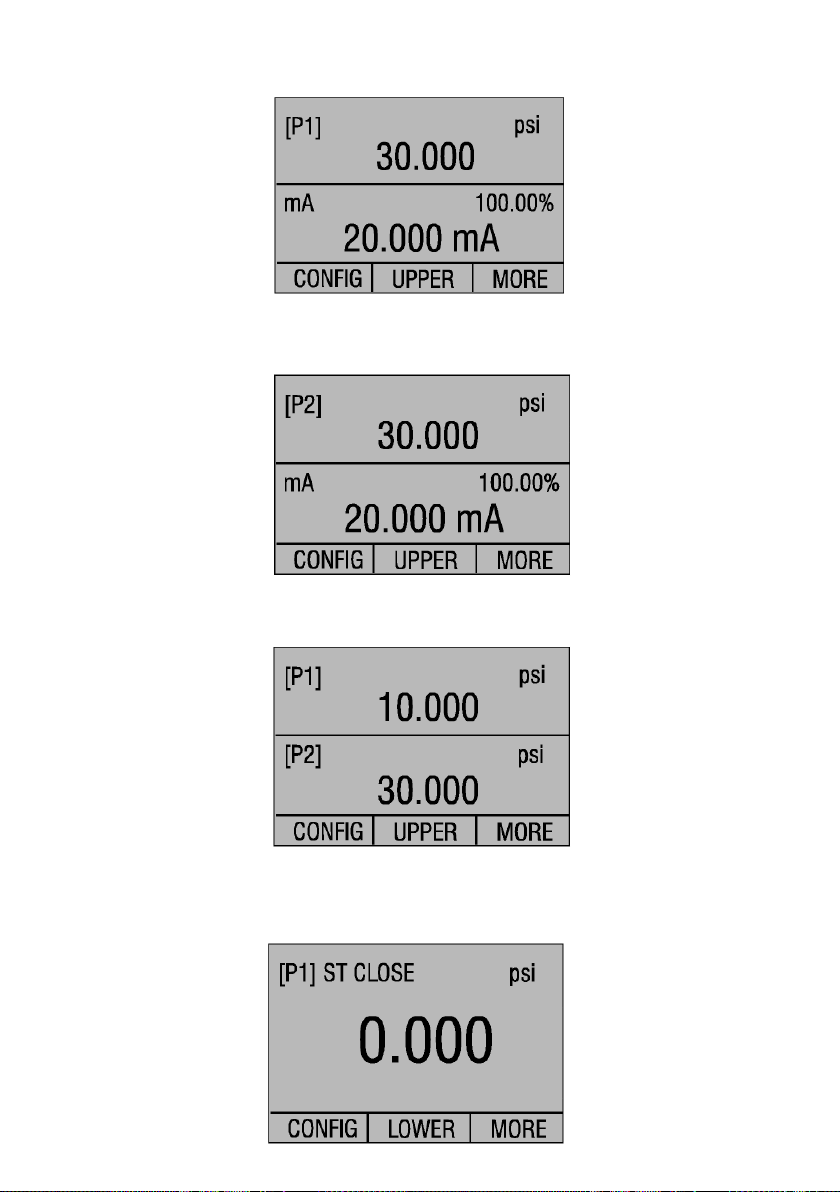
9. Factory Setups
The Calibrator is loaded with five factory setups. These setups are shown below.
Setup 1: The upper display is set to [P1] mode and the middle is set to mA, lower is off.
Setup 2: The upper display is set to [P2] mode and the middle is set to mA, lower is off.
Setup 3: The upper display is set to [P1] mode and the middle is set to [P2], lower is off.
Setup 4: The lower display is set to [P1] switch test, the other displays are off.
This manual suits for next models
1
Table of contents
Other Ecom Test Equipment manuals


