BioHorizons INTRASPIN IS220 User manual
Leukocyte- and Platelet-Rich Fibrin
L02065 Rev A AUG 2020

English
Instructions for use: IntraSpin
Español
Instrucciones de uso: IntraSpin
русский
Инструкция по применению: IntraSpin
DEUTSCH
Gebrauchsanweisung: IntraSpin
FRANÇAIS
Instructions d'utilisation: IntraSpin
ITALIANO
Istruzioni per l'uso: IntraSpin
PORTUGUÊS
Instruções de utilização: IntraSpin
Türk
Kullanım talimatları: IntraSpin
简体中文
使用说明:IntraSpin
日本語
使用説明書:IntraSpin
한국어
사용 설명서: IntraSpin
يبرع
IntraSpin
Polskie
Polskie
Polskie
Instrukcja użycia: IntraSpin
čeština
čeština
čeština
češtinaPolskie
Polskie
Návod k použití: IntraSpin
BioHorizons
2300 Riverchase Center
Birmingham, AL 35244 USA
+1-205-967-7880
IntraSpin®, Xpression® & L-PRF® are registered trademarks of BioHorizons; Vacuette® is a registered trademark of
Greiner Bio-One International AG.; Enzymax® is a registered trademark of Hu-Friedy Mfg. Co., LLC.

1 of 31
ENGLISH
The symbol table below is for reference only. Refer to product or product packaging label for applicable
symbols.
Symbol
Symbol Description
Caution
Electronic instructions for
use
Manufacturer
BioHorizons products carry
the CE mark and fulfill the
requirements of the
Medical Devices Directive
93/42/EEC
Reference/ article number
Lot/ batch number
Do not re-use
Use-by-date
Sterile by gamma
irradiation
Date of manufacture
Rx Only
Caution: U.S. Federal law
restricts these devices for
sale, distribution and use
by, or on the order of, a
dentist or physician
Symbol
Symbol Description
Home position
Do not use if package is
damaged
Medical Device
Non-sterile
Keep dry
Fragile; handle with care
Temperature limits
This way up
Humidity limits
Warning; Biological hazard
Important note(s)
Separate collection of
electric and electronic
devices.
Authorized representative
in the European
Community
MD
Non-sterile

2 of 31
INDICATIONS FOR USE
The IntraSpin System is intended to be used for the safe and rapid preparation of autologous Leukocyte- and
Platelet-Rich Fibrin (L-PRF) from a small sample of blood at the patient's point of care. The L-PRF is mixed
with autograft and/or allograft bone prior to application to a bony defect for improving handling characteristics.
Observing all information in the Instructions for Use is also a part of the intended use.
CONTRAINDICATIONS
The IntraSpin centrifuge is only meant for the purpose stated in the intended use of the device. Any other
use of the device is considered non-intended. Use of the IntraSpin centrifuge is contraindicated in the
presence of one or more of the following clinical situations: Patients with alcohol addiction or psychiatric
disorders, blood dyscrasias, uncontrolled diabetes, hyperthyroidism, oral infections, malignancies or patients
who have had myocardial infarction within the last 12 months. Patients with systemic diseases that
compromise the immune system, such as AIDS, patients on medications that would compromise healing of
an implant site, patients with a history of poor or noncompliance to oral hygiene procedures.
Patients who are participating in anti-coagulant therapy. These patients are not excluded from the benefits
of PRF, instead the point of care must add additional time to the centrifuge for the separation to be effective
for use.
SAFETY NOTES
▪No claim of warranty will be considered by the manufacturer unless ALL instructions in this manual
have been followed.
▪The operating instructions are a part of the device. They must always be kept readily available. If the
device is set up at a different location, the operating instructions must be provided with it.
▪The centrifuge should be installed on a good, stable base.
▪Before using the centrifuge absolutely check the rotor for firm placement.
▪When the centrifuge is running, no persons, dangerous substances or objects may be within the
safety margin of 300 mm around the centrifuge.
▪Rotors, suspensions and accessories that possess traces of corrosion or mechanical damage or if
their term of use has expired may not be used any longer.
▪The centrifuge may no longer be put into operation when the centrifuging chamber has safety-related
damages.
▪For centrifuges without temperature control, when the room temperature is increased and/or if the
device is frequently used, the centrifuging chamber could be heated up. Therefore, it can't be ruled
out that the sample material might be changed due to the temperature.
▪Before the initial operation of your centrifuge you should read and pay attention to the operating
instructions. Only personnel that has read and understood the operating instructions are allowed to
operate the device.
▪Along with the operating instructions and the legal regulations on accident prevention, you should
also follow the recognized professional regulations for working in a safe and professional manner.
These operating instructions should be read in conjunction with any other instructions concerning
accident prevention and environmental protection based on the national regulations of the country
where the device is to be used.

3 of 31
▪Meeting the country-specific requirements concerning occupational safety with regard to the use of
laboratory centrifuges at the workplaces provided for this purpose by the user is the responsibility of
the user.
▪This centrifuge is a state-of-the-art piece of equipment which is extremely safe to operate. However,
it can lead to danger for users or others if used by untrained staff, in an inappropriate way or for a
purpose other than that it was designed for.
▪The centrifuge must not be moved or knocked during operation.
▪In case of fault or emergency release, never touch the rotor before it has stopped turning.
▪To avoid damage due to condensate, when changing from a cold to a warm room the centrifuge
must either heat up for at least 3 hours in the warm room before being connected to the mains or run
hot for 30 minutes in the cold room.
▪When centrifuging with maximum revolutions per minute the density of the materials or the material
mixtures may not exceed 1.2 kg/dm3.
▪The centrifuge may only be operated when the balance is within the bounds of acceptability.
▪The centrifuge may not be operated in explosion-endangered areas.
▪The centrifuge must not be used with inflammable or explosive materials or materials that react with
one another producing a lot of energy.
▪No biosafety systems are available for this centrifuge.
▪The centrifuge must not be operated with highly corrosive substances which could impair the
mechanical integrity of rotors, hangers and accessories.
▪Repairs must only be carried out by personnel authorized to do so by the manufacturer.
▪In order to offer patients the highest level of clinical safety, IntraSpin products are made with
materials that are biocompatible with human plasma.
▪This product is not authorized for sale in every market and it may not be available in your market.
Please consult with your local representative for additional information.
INTRASPIN SYSTEM COMPONENTS
COMPONENT
QUANTITY PER SYSTEM
IntraSpin Centrifuge including:
1
Power Cable
1
Fuse
2
Hex Hand Wrench
1
IntraSpin Blood Collection Tubes –9 ml plastic tubes (single use)
150
Greiner Safety Blood Collection Set + Holder, 21G (single use)
24
Latex Free Tourniquet
1
Test Tube Rack
1
Surgical Curved Scissors
1
Surgical Tissue Forceps
1
Round Stainless-Steel Bowl
1
Rectangular Stainless-Steel Bowl
1
Dual Biomaterial Carrier Spatula
1
Dual Biomaterial Packer
1
Xpression® Box
1

4 of 31
Only verified compatible components for direct use with the IntraSpin centrifuge are recommended and
warranted:
COMPATIBLE PART #
DESCRIPTION
WCT_50 (455006)
IntraSpin White Blood Collection Tubes
BVBCTP2_50 (455385)
IntraSpin Blood Collection Tubes
455092
Tube 9ml Serum Clot activator, red cap (50 pcs)
455001
White Cap 9ml No additive blood collection tube (50 pcs)
BHEXZ (E613)
IntraSpin Hex Key, 110v & 220v
BROTORZ (E3694)
IntraSpin Rotor, 100v & 220v
BPOWER110Z (E1673)
IntraSpin Power Cord, 110v
BPOWER220Z (E1669)
IntraSpin Power Cord, 220v
BTUBEHOLDZ (E872 x 1)
IntraSpin Tube Holder Replacement
BFUSE110Z (E997)
IntraSpin Fuse IS110
BFUSE220Z (E891)
IntraSpin Fuse IS220
BRIEF CENTRIFUGE SETUP
Remove and save transport bolts from bottom of centrifuge.
Attach AC cable and plug into electrical outlet.
Power centrifuge on by using the rocker switch on the back of the device.
Select speed and time: Speed = 2700 & Time = 12:00 min.
Press START.
The centrifuge cover will open automatically at the end of each cycle.
After the first procedure, the timing and speed are recorded in the centrifuge memory unless the settings are
changed.
BLOOD COLLECTION TUBES CAUTIONS AND INSTRUCTIONS
▪Handle all biological samples and blood collection “sharps” (e.g. needles, and blood collection sets)
according to the policies and procedures of your facility.
▪Obtain appropriate medical attention in the case of any exposure to biological samples (e.g. via
puncture injury) due to the possible transmission of HIV (AIDS), viral hepatitis or other infectious
diseases.
▪Discard all blood collection “sharps” in approved biohazard containers.
▪Transferring a sample from a syringe to a tube is not a recommended procedure.
▪If blood is collected through an intravenous (IV) line, follow the policies and procedures of your
institution to ensure that the line has been cleared of IV solution before beginning to fill the blood
collection tubes.
▪Blood clotting accelerant may appear white on the tube surface, which has no effect on the
performance of the tubes. If any other discoloration or precipitates are present in the tube, it should
not be used.
▪Do not use the tubes after the expiration date.
▪Store tubes at 4–25°C (40–77°F).
▪Avoid exposure to direct sunlight. Exceeding the maximum recommended storage temperature may
lead to impairment of the tube quality (i.e. vacuum loss, coloring, etc.).

5 of 31
▪To prevent backflow, place the patient’s arm in a downward position, hold the tube with the cap up,
release the tourniquet as soon as blood starts to flow into the tube, avoid tube contents coming in
contact with cap or end of the needle during venipuncture.
▪Be sure that the following materials are readily accessible before performing venipuncture: all
necessary blood collection tubes, identified labels for positive patient identification of samples,
blood collection needles and holders, alcohol swab for cleansing the puncture site, clean gauze,
tourniquet, adhesive plaster or bandage, approved biohazard container. For protection against
exposure to bloodborne pathogens, appropriate PPE (Personal Protective Equipment) is
recommended (e.g. gloves, laboratory coat, goggles, etc.).
Venipuncture Technique and Blood Sample Collection:
The blood collection must be made as quickly as possible, since there is no anticoagulant in the collection
tubes. The blood sample will begin to coagulate immediately. Wear gloves during venipuncture and when
handling blood collection tubes to minimize exposure hazard. Prior to the blood draw, wipe the top of the
blood tube cap(s) with a disinfectant wipes of your choice. Remove the cover over the valve section of the
needle. Prepare venipuncture site with an appropriate antiseptic. Do not palpate venipuncture area after
cleansing. Place the patient’s arm in a downward position. Remove the needle shield. Perform the
venipuncture with the arm downward and tube cap upper-most. Push the blood collection tube into the holder
and onto the needle valve puncturing the rubber diaphragm of the blood collection tube. Center the blood
collection tubes in the holder when penetrating the cap to prevent sidewall penetration and subsequent
premature vacuum loss. Remove the tourniquet as soon as blood appears in the blood collection tube. During
procedure, always hold the collection tube in place by pressing it with a thumb. This will ensure a complete
vacuum draw. The blood collection tube will fill automatically. If no blood flows into collection tube or if blood
flow ceases before an adequate specimen is collected, the following steps are suggested to complete a
satisfactory collection:
▪Push the blood collection tube forward to ensure the cap has been penetrated.
▪Confirm the correct position of the needle in the vein.
▪If blood still does not flow, remove and appropriately discard the collection tube. Obtain a new
collection tube and push into holder.
▪If the second collection tube does not draw, remove and appropriately discard the needle and the
collection tube. Repeat the procedure.
▪When the maximum volume fill line of the blood collection tube bas been reached, gently remove it
from the holder. Repeat with a second blood collection tube.
▪Gently invert each collection tube immediately upon removing from the holder. Do not shake the
tubes filled with blood sample. Vigorous mixing may cause foaming or hemolysis. Insufficient mixing
or delayed mixing in serum tubes may result in delayed clotting.
Upon completion of blood sample collection, remove the needle from the vein. Activate the safety mechanism
of the needle. Apply pressure to the puncture site with a dry sterile swab until the bleeding stops. If desired,
apply a bandage once clotting has occurred. It is recommended that filled collection tubes, be kept in an
upright position. Once the second blood collection tube is full, remove it and place the first and second tubes
into the centrifuge on opposite locations to counterbalance the rotor. Close the cover of the IntraSpin
centrifuge and press the START button to allow it to spin for 12 minutes.

6 of 31
If more than two tubes of blood are required, please follow this alternative procedure: After the first two tubes
of blood are collected, immediately place them into the IntraSpin centrifuge, opposite from each other to
ensure the centrifuge is properly balanced. Close the cover and press the START button and allow the
centrifuge to run while you collect the remaining tubes of blood. Press the STOP button and allow the
centrifuge to come to a full stop. The cover will pop open; immediately place the remaining tubes in the
centrifuge opposite from each other to ensure proper balance and press the START button to reset and
complete recommended protocol.
Always place the tubes in pairs and place them in opposite positions to balance the centrifuge rotor. The
tubes must always be balanced in the rotor before pressing the START button or this may cause serious
damage to the centrifuge, improper coagulation, and/or separation. If the tubes are not properly balanced,
there will be too much vibration during centrifugation and a poor L-PRF fibrin clot will result.
If you have an odd number of blood samples to centrifuge, then place a tube of the same size as the blood
samples, filled with water to the indicated full line, opposite to the un-paired tube in the rotor. This will allow
for proper balancing of the centrifuge.
Begin centrifugation immediately after collecting the blood samples. Delays affect the blood separation
procedure and result in a poor L-PRF fibrin clot.
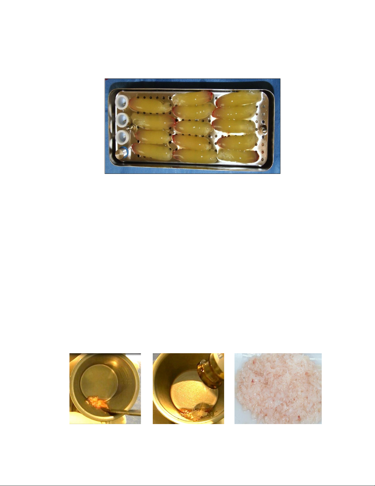
L-PRF PREPARATION
After centrifugation, three segments are visible:
1. Upper Segment = platelet poor plasma (PPP).
2. Middle Segment = fibrin clot: L-PRF.
3. Lower Segment= red blood cell clot.
L-PRF fibrin membranes or plugs must be prepared relatively quickly: 0-15 minutes after centrifugation or the
clot will shrink in volume by releasing the trapped serum. After centrifugation, remove the rubber stopper
from each tube. Using the Surgical Tissue Forceps remove the L-PRF clot from the tube. Gently scrape the
red blood cell clot from the L-PRF® fibrin clot just below the union, using the Dual Biomaterial Carrier Spatula,
so that only a minimal, residual amount of red blood cells are attached to L-PRF clot. Place the fibrin clot
onto the Xpression Perforated Tray.
FIBRIN MATRIX PREPARATION
Protocol #1 L-PRF Membrane
Place each of the fibrin clots on the Xpression Perforated Tray. Once all of the fibrin clots are placed,
place the Xpression Compression Plate and Xpression Weighted Cover over the fibrin clots without
exerting any pressure over the clots.
Allow the weight of the cover to slowly press down the fibrin clot while the exudate is filtered to the bottom
of the tray. Do not apply pressure to the weighted cover. Gravitational force on the weighted cover will
gently compress the clot and express the serum from the L-PRF clot without damaging the fibrin network.
7 of 31
Wait at least 5 minutes before removing and using any fibrin membranes. Do not remove any fibrin
membranes until actual time of use. The fibrin membrane may remain in the Xpression Box for a period
of up to 3 hours.
Protocol #2 L-PRF Plug
Place a fibrin clot inside the white plug fabrication cylinder. Use the piston to slowly press the clot inside
the white L-PRF plug fabrication cylinder. Continue to press until the top edge of the piston is flush with
the top edge of the white L-PRF plug fabrication cylinder. With this technique, one will be able to form a
thick, round fibrin plug for the extraction socket. For a single tooth, one L-PRF plug may be sufficient.
Pre-molars may need two L-PRF plugs, and three L-PRF plugs may be needed for molars, depending
on the size of the extraction socket and the size of the fibrin clot created.
The working properties of L-PRF provide an excellent medium for use in combination with
your biomaterial of preference. Utilizing any of the following mixing protocols, the biomaterial
is captured in the fibrin matrix increasing its handling and biologic capacity.
Protocol #3- Biomaterial/L-PRF Mixture
To create a ‘putty like’ mixture that can be gently formed with the biomaterial instrument into the desired
shape and thickness use the following protocol: Gently cut the L-PRF fibrin membrane into small pieces
in a sterile dish with the Surgical Curved Scissors. Add the desired amount of bone graft material.
Thoroughly mix the L-PRF and bone graft material. This mixture can be placed into defects using the
Dual Biomaterial Carrier Spatula.
8 of 31
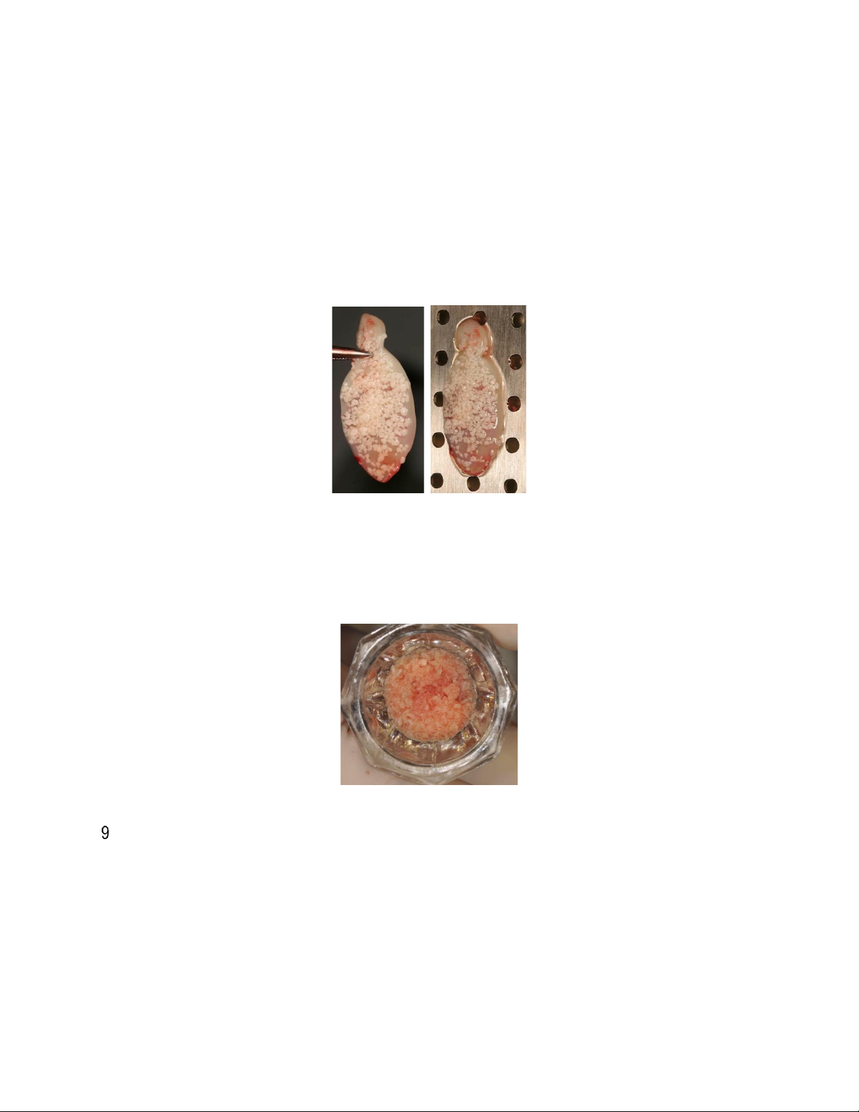
Protocol #4- Biomaterial/L-PRF Matrix Mixture
Place the predetermined amount of bone graft material into a sterile bowl or tray. Dip the expressed L-
PRF membrane(s) or pieces of the L-PRF membrane into the graft material covering the entire surface
area of the L-PRF membrane with graft material. Alternatively, the graft material may be sprinkled onto
the L-PRF membrane covering the entire surface area with graft material. Note: A wetter L-PRF
membrane may retain slightly more graft material than a dryer L-PRF membrane. The graft material
should cling to the surface of the L-PRF, however, if desired, gently press the graft material onto the L-
PRF membrane. The Surgical Tissue Forceps can be used to place this mixture into the defect.
Protocol #5- Biomaterial Hydration
Add the desired amount of bone graft material into a sterile bowl or tray. Utilize the exudate from the
bottom of the Xpression Collection Tray to hydrate the graft material. Thoroughly mix the exudate and
bone graft material. This mixture can be placed into defects using the Dual Biomaterial Carrier Spatula.
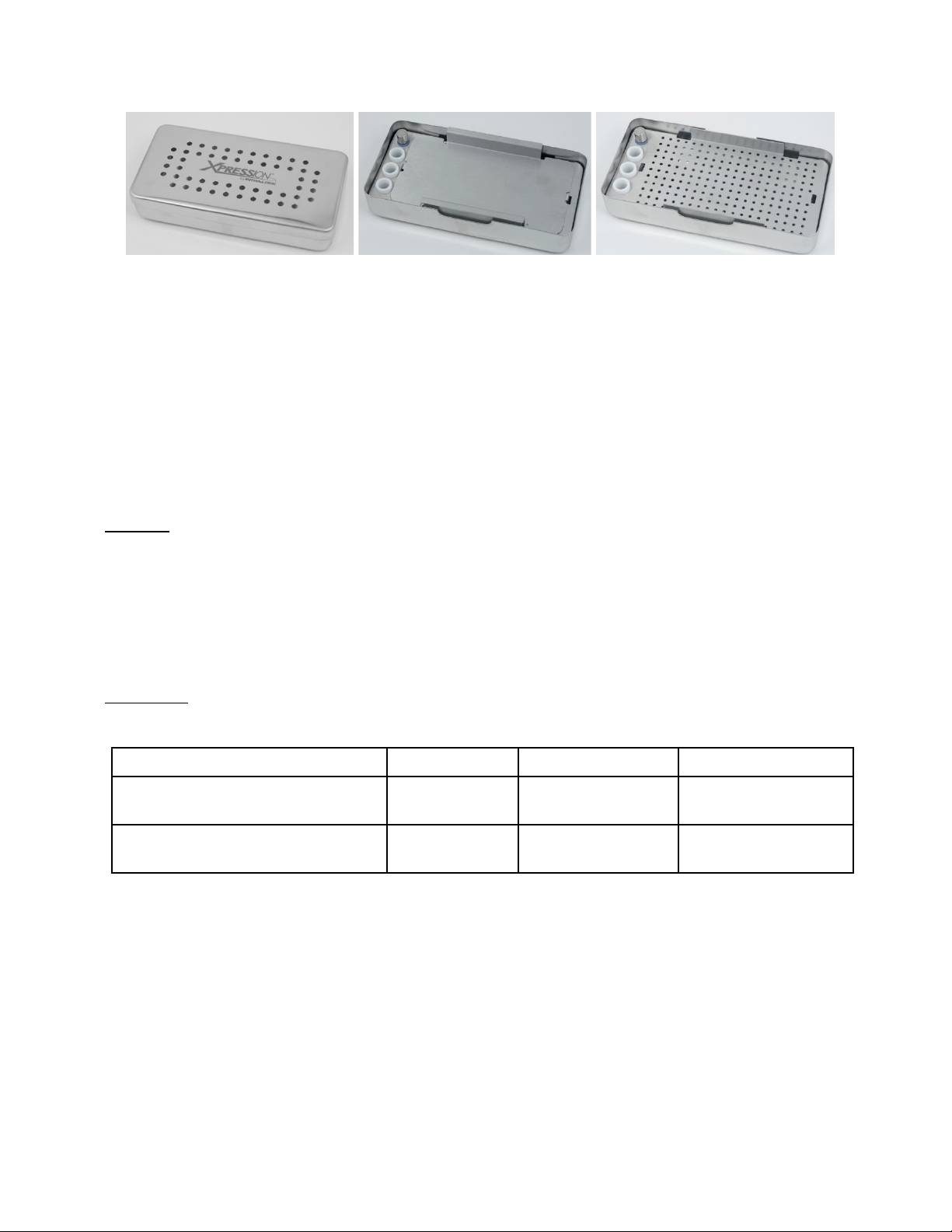
TISSUE REGENERATION KIT CLEANING AND STERILIZATION
The Xpression Box enables the fabrication of fibrin membranes of constant thickness with ease. The exudate
can be collected from the Xpression Collection Tray, underneath the Xpression Perforated Tray. The
Xpression Box includes L-PRF plug fabrication cylinders and a piston to fabricate L-PRF plugs that easily fit
post-extraction sockets.
9 of 31
Xpression Weighted Cover
Xpression Compression Plate
Xpression Perforated Tray in
Xpression Collection Tray
The Xpression Box and ancillary instruments are NOT supplied sterile. Remove and discard any shipping
material before initial sterilization. Clean and sterilize the Xpression Box and ancillary instruments before
each use.
Disassemble the Xpression Box before each cleaning and sterilization cycle to avoid debris encapsulation,
material discoloration, and/or inadequate drying of components. The L-PRF plug fabrication cylinders and
piston grommet are not intended to be removed from the Xpression Perforated Tray for cleaning and
sterilization.
Cleaning: (1) Remove any visible debris from the Xpression Box components and ancillary instruments using
a soft bristle brush and a broad-spectrum cleaning or disinfecting agent such as Hu-Friedy’s Enzymax® or
equivalent. Rinse thoroughly. (2) Place the Xpression Box components and ancillary instruments in an
appropriately sized container of the same solution and sonicate for 10 minutes. Rinse thoroughly. (3) Rinse
the Xpression Box components and ancillary instruments with isopropyl alcohol to remove any soap residue
and minerals. (4) Blot the Xpression Box components and ancillary instruments with a lint-free towel and air
dry completely. Refer to the labeling of the cleaning agent used for instructions for use.
Sterilization: (1) Place the reassembled Xpression Box and ancillary instruments in an FDA cleared
sterilization bag or wrap. (2) Run through one of the following qualified sterilization cycles:
Sterilization Method
Temperature
Exposure Time
Minimum Drying Time
Pre-vacuum Steam (ANSI/AAMI ST79)
132°C (270°F)
4min
20-30 minutes
Pre-vacuum Steam (UK DoH Health
Technical Memorandum 01-01)
134°C (273°F)
3min
20-30 minutes
Attention! Improper cleaning may lead to inadequate sterilization. Failure to completely dry the Xpression Box
components and ancillary instruments during autoclaving may leave moisture and cause discoloration and
oxidation. The use of hydrogen peroxide or other oxidizing agents will damage the surface of the Xpression
Box components and ancillary instruments. Periodic testing, cleaning, and calibration of the autoclave
equipment is recommended to ensure the unit remains in proper working order.

10 of 31
CENTRIFUGE CLEANING AND MAINTENANCE
The device can be contaminated. Pull the mains plug before cleaning. Centrifuges, rotors and accessories
must not be cleaned in rinsing machines. They may only be cleaned by hand and disinfected with liquids. The
water temperature must be between 20 –25°C. Only detergents/disinfectants with a pH between 5 - 8 and
that do not contain caustic alkalis, peroxides, chlorine compounds, acids and alkaline solutions may be used.
In order to prevent appearances of corrosion through cleaning agents or disinfectants, the application guide
from the manufacturer of the cleaning agent or disinfectant must be considered.
Clean the centrifuge housing and the centrifuging chamber regularly, using soap or a mild detergent and a
damp cloth if required to prevent corrosion through adhering impurities. Ingredients of suitable detergents
include soap, anionic surfactants and non-ionic surfactants. After using detergents, remove detergent residue
by wiping with a damp cloth. The surfaces must be dried immediately after cleaning. In the event of water
condensation, dry the centrifugal chamber by wiping out with an absorbent cloth. Lightly rub the rubber seal
of the centrifuge chamber with talcum powder or a rubber care product after each cleaning. The centrifuging
chamber is to be checked for damage. If damage is found to be relevant to safety, the centrifuge may no
longer be put into operation. In this case, notify Customer Service.
For surface disinfection, if infectious materials penetrate into the centrifugal chamber, it must be disinfected
immediately. Ingredients of suitable disinfectants include ethanol, n-propanol, ethyl hexanol, anionic
surfactants and corrosion inhibitors. After using disinfectants, remove disinfectant residue by wiping with a
damp cloth. The surfaces must be dried immediately after disinfecting.
For removal of radioactive contaminants, the agent must be specifically labelled as being an agent for
removing radioactive contaminants. Ingredients of suitable agents for removing radioactive contaminants
include anionic surfactants, non-ionic surfactants, polyhydrated ethanol. After removing the radioactive
contaminants, remove the agent residue by wiping with a damp cloth. The surfaces must be dried directly after
removing the radioactive contaminants.
ROTOR AND ACCESSORIES CLEANING AND MAINTENANCE
To avoid corrosion and changes to the materials, the rotor and accessories have to be cleaned regularly with
soap or a mild cleaning agent and a moist cloth. Cleaning is recommended at least once a week.
Contaminants must be removed immediately.
Ingredients of suitable detergents include soap, anionic surfactants and non-ionic surfactants. After using
detergents, remove detergent residue by rinsing with water (only outside of the centrifuge) or wipe off with a
damp cloth. The rotor and accessories have to be dried immediately after cleaning. Check the rotor and
accessories weekly for wear and corrosion damage. The rotor and accessories must no longer be used if
they show signs of wear or corrosion. Check the firm seating of the rotor on a weekly basis. If infectious
material should get on the rotor or accessories, they must be appropriately disinfected.
Ingredients of suitable disinfectants include ethanol, n-propanol, ethyl hexanol, anionic surfactants and
corrosion inhibitors. After using disinfectants, remove disinfectant residue by rinsing with water (only outside
of the centrifuge) or wipe off with a damp cloth. The rotor and accessories must be dried directly after
disinfection.

11 of 31
For removal of radioactive contaminants, the agent must be specifically labelled as being an agent for the
removal of radioactive contaminants. Ingredients of suitable agents for removing radioactive contaminants
include anionic surfactants, non-ionic surfactants and polyhydrated ethanol. After removing the radioactive
contaminants, remove agent residue by rinsing with water (only outside of the centrifuge) or wipe off with a
damp cloth. The rotor and accessories must be dried directly after removing the radioactive contaminants.
The rotor may be autoclaved at 121oC/250oF for 20 minutes and dried appropriately. After 10 autoclaving
cycles, the rotor must be exchanged for safety reasons. Autoclaving accelerates the ageing process of
plastics and may cause discoloration. After autoclaving, wait until the rotor has cooled down to the ambient
temperature before using it again. No statement can be made about the degree of sterility.
The period of use of the rotor is limited to 50,000 running cycles (centrifugation runs) or 5 years, whichever
comes first. The maximum permissible number of run cycles can be seen on the rotor. For safety reasons,
the rotor may no longer be used when the maximum allowed number of running cycles (marked on it) has
been reached. The device is equipped with a cycle counter which counts the running cycles (centrifugation
runs).
In case of blood tube fracture, all broken parts and blood are to be completely removed. The centrifuge is to
be thoroughly cleaned as indicated and rubber inserts as well as plastic sleeves of the rotor are to be
replaced.

12 of 31
CENTRIFUGE TECHNICAL SPECIFICATIONS
Model Type
IS220
IS110
Mains voltage (10%)
200 - 240 V 1
100 - 127 V 1
Mains frequency
50 - 60 Hz-
50 - 60 Hz
Connected load
100 VA
100 VA
Current consumption
0.5 A
1.0 A
Capacity
8 x 10 ml
Maximum allowed density
1.2 kg/dm3
Maximum Speed (RPM)
6,000
Force (RCF)
3,461
Kinetic energy
750 Nm
Set-up site
Indoors only
Altitude
Up to 2000 m above sea level
Ambient temperature for operation
5°C to 40°C
Relative Humidity for operation
Maximum relative humidity 80% for temperatures up to 31°C,
linearly decreasing to 50% relative humidity at 40°C.
Excess-voltage category
Pollution degree
2
Device protection class
Not suitable for use in explosion-endangered areas.
Emitted interference, Interference immunity
EN / IEC 61326-1, Class B
FCC Class B
Noise level (dependent on rotor)
50 dB(A)
Centrifuge width
261 mm
Centrifuge Depth
353 mm
Centrifuge Height
228 mm
Centrifuge Weight
approx. 9 kg
13 of 31
CENTRIFUGE OPERATING INSTRUCTIONS
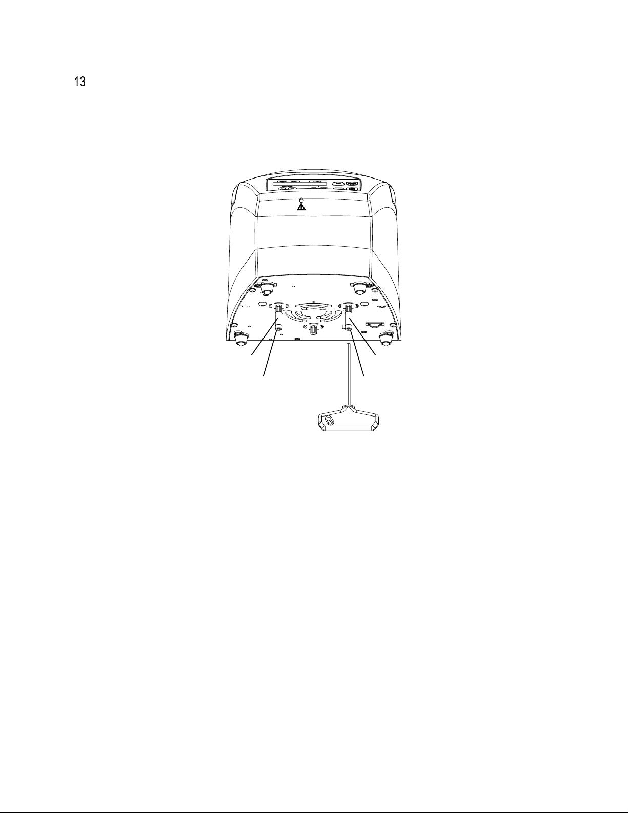
It is imperative that the transport securing device, consisting of 2 screws and 2 spacers, be removed. Keep
the transport securing device in a safe place since it must be installed again before transporting the device.
The device may only be transported with the transport securing device installed. To protect the device from
damage during transport, the motor is fixed in place. This transport securing device must be removed when
the device is put into operation.
13.1 INITIAL OPERATION
▪Remove the transport securing device from the centrifuge bottom side.
▪Position the centrifuge in a stable and level manner in a suitable place. When the centrifuge is
running, no persons, dangerous substances or objects may be within the safety margin of 300 mm
around the centrifuge.
▪Ventilation openings must not be blocked. A distance of 300 mm must be maintained from the
ventilation slots and openings of the centrifuge.
▪Check whether the mains voltage tallies with the statement on the type plate.
▪Connect the centrifuge with the power cord to a standard mains socket.
▪Switch on the mains switch.
▪The following displays appear on the panel: the centrifuge model type, the software version, and the
last used centrifugation data.
▪If the lid is closed, the message "Open the lid" is displayed. In this case, open the lid to display the
centrifugation data.
13.2 OPENING AND CLOSING THE CENTRIFUGE LID
The lid can only be opened if the centrifuge is switched on and the rotor is stationary. When the cycle counter
is activated, after a centrifugation run, while opening the lid, the remaining number of running cycles
(centrifugation runs) is briefly displayed.
(a)
(b) (b)
(a)

14 of 31
Example:
To open the lid, Press the following key . The lid is unlocked by the motor. indicates lid
unlocked.
Example:
Do not reach with your fingers between the lid and housing. Do not slam the lid closed.
To close the lid, lightly press down the front edge of the lid. indicates lid locked.
Example:
13.3 EMERGENCY UNLOCKING
In the event of a power failure, the lid cannot be unlocked with the motor. Emergency unlocking must be done
by hand. To unlock in an emergency, switch off the mains switch (switch setting "0"). Look through the window
in the lid to make sure that the rotor is at a standstill. Open the lid only when the rotor is at a standstill. Insert
the Allen key horizontally in the bore (A) and turn carefully counterclockwise (to the left) until the lid opens.
CAUTION! Turning the hexagon Allen key in clockwise direction (to the right) may damage the locking
system. Pull the Allen key back out of the bore.
t/min:sRPM>RCF<
STOP
OPEN
t/min:sRPM>RCF<
t/min:sRPM>RCF<
A

15 of 31
13.4 INSTALLATION AND REMOVAL OF THE ROTOR
To remove the rotor, loosen the rotor's clamping nut by turning counter-clockwise with the Allen wrench
(included in delivery) and turn up to the lifting pressure point. After overcoming the lifting pressure point, the
rotor is released from the cone of the motor shaft. Turn the clamping nut until the rotor can be lifted up from
the motor shaft. Lift up the rotor from the motor shaft.
To install the rotor, clean the motor shaft (A) and the bore of the rotor and apply a thin coat of grease to the
motor shaft. Dirt particles between the motor shaft and rotor prevent the rotor from having a perfect seat and
cause it to run unsteadily. Place the rotor vertically onto the motor shaft. When putting on the rotor, the
marking beam (B) on the rotor must be parallel to both surfaces (C) on the motor shaft. Tighten the clamping
nut of the rotor with the Allen wrench (included in delivery) by turning clockwise. Check the rotor to make
sure it is seated firmly.
The rotors must be loaded symmetrically. The blood tubes have to be distributed evenly on all rotor positions.
Rotor evenly loaded
Rotor not evenly loaded
Not permitted!
The blood tubes may only be filled outside of the centrifuge. The maximum filling quantity for the blood tubes
is specified on the tubes themselves and must not exceed the maximum weight listed on the rotor. The
centrifuging vessels may only be filled so far that no fluid can be expelled from them while the centrifuge is
running. When loading the rotor, no liquid may enter the rotor or the centrifuging chamber. In order to maintain
the weight differences within the centrifuge container as marginal as possible, a consistent fill level in the
blood tubes is recommended.
A
B
C
16 of 31
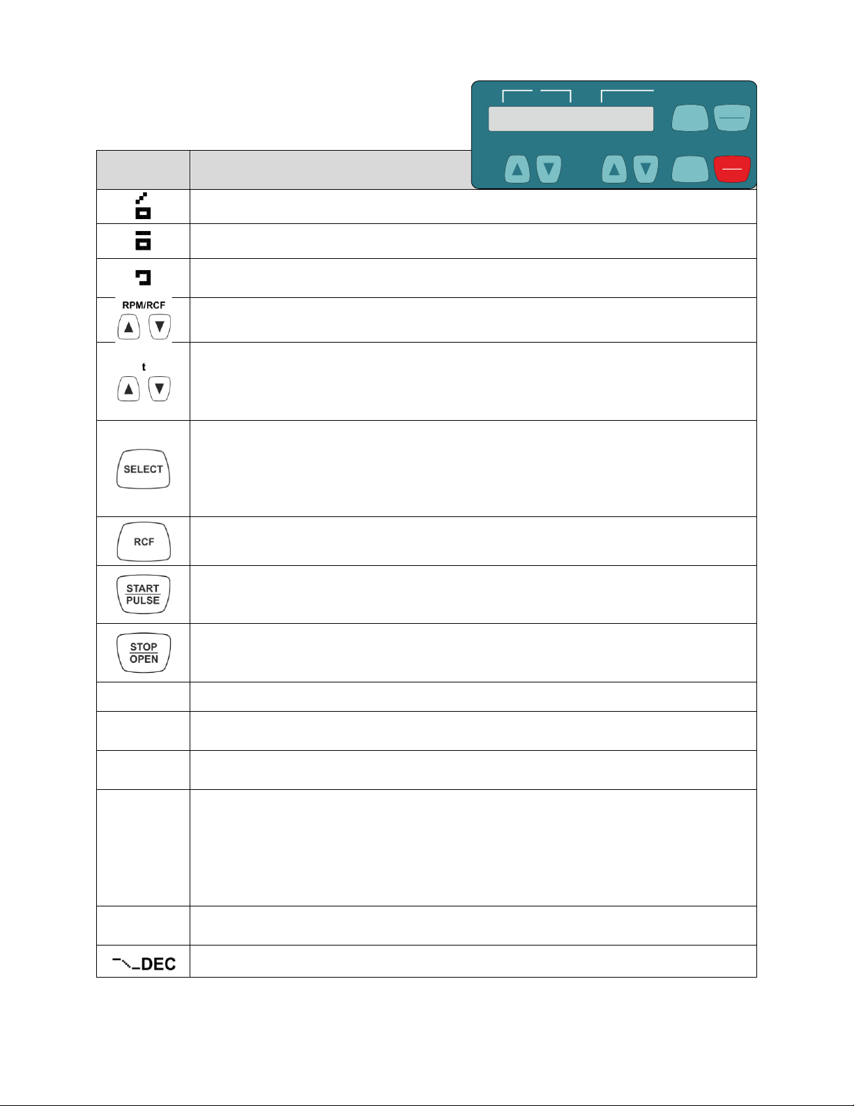
13.5 DISPLAY ELEMENTS DESCRIPTION
Symbol /
Panel Key
Description
Lid unlocked.
Lid locked.
Rotation display. The rotation display lights up, rotating in a clockwise direction, when the
rotor is turning.
To input speed directly. If the key is kept pressed, the value changes with increasing
speed.
To input the runtime directly. Adjustable in steps of 1 second up to a minute, and in steps
of 1 minute starting from 1 minute.
To input the centrifugation parameters. If the key is kept pressed, the value changes with
increasing speed.
To activate individual parameters. Every time the key is pressed, the next parameter is
activated.
Keep the key pressed for 8 seconds to call up the "MACHINE MENU".
In the "Machine Menu", select the menus "->Info", "->Settings" and "Time & Cycles".
To scroll forward in the menus.
To switch between the speed display (RPM) and relative centrifugal force display (RCF).
RCF values are displayed between arrows ><.
To start the centrifugation run.
For short-term centrifugation. Centrifugation is run as long as the key is kept pressed.
To select the menus "->Info", "->Settings" and "->Time & Cycles".
To finish the centrifugation run. The rotor runs down with a pre-selected brake stage.
Pressing the key twice triggers the Emergency Stop.
To unlock the lid.
t/min
Runtime. Adjustable from 1 - 99 minutes, in steps of 1 minute.
t/sec
Runtime. Adjustable from 1 - 59 seconds, in steps of 1 second.
Continuous run "--:--". Set the parameters t/min and t/sec to zero.
RPM
Speed. A number value from 200 RPM to the maximum speed of the rotor can be set.
Adjustable in steps of 10.
>RCF<
Relative centrifugal force. A number value can be set which results in a speed between
200 RPM and the maximum rotor speed. Adjustable in steps of 1.
It is only possible to input the relative centrifugal force (RCF) if the RCF display (>RCF<) is
activated. The relative centrifugal force (RCF) depends on the centrifuging radius (RAD).
After entering the RCF, check to make sure that the correct centrifuging radius has been
set.
RAD/mm
Centrifuging radius. Adjustable from 10 mm to 250 mm, in steps of 1 mm. It is only
possible to input the centrifuging radius if the RCF display >RCF< is activated.
Brake stage. fast = short run-out time, slow = long run-out time.
SELECT
t/min:s
RPM
>RCF<
RPM/RCF t
RCF
STOP
OPEN
START
PULSE

17 of 31
13.6 DIRECT INPUT OF THE CENTRIFUGATION PARAMETERS
The speed (RPM), the relative centrifugal force (RCF), the centrifuging radius (RAD) and the runtime can be
inputted directly with the keys without previously having to press the key. The set
centrifugation parameters are only stored after starting the centrifugation run.
For Speed (RPM):
Example:
Press the key to activate the RPM display (RPM) as needed.
RPM/RCF
Set the desired value with the keys.
For Relative Centrifugal Force (RCF) and Centrifugal Radius (RAD):
Example:
Press the key to activate the RCF display ( RCF ) as needed.
↓
RPM/RCF
Set the desired RCF value with the keys.
↓
t
Set the desired centrifuging radius with the keys as needed.
Runtime:
Up to 1 minute, the runtime can be set in steps of 1 second, and starting from 1 minute, it can only be set in
steps of 1 minute. In order to set the continuous run, the parameters t/min and t/sec must be set to zero. In
the time display (t/min:s), "--:--" appears.
Example:
SELECT
RCF
t/min:sRPM>RCF<
t/min:sRPM>RCF<
RCF
t/min:sRPM>RCF<
t/min:sRPM>RCF<
t/min:sRPM>RCF<
t/min:sRPM>RCF<
t/min:sRPM>RCF<
Example:
t
Set the desired value with the keys.
t/min:sRPM>RCF<

18 of 31
13.7 INPUT OF THE CENTRIFUGATION PARAMETERS WITH THE "SELECT" KEY
The runtime can be set in minutes and seconds (parameters t/min and t/sec). In order to set the continuous
run, the parameters t/min and t/sec must be set to zero. In the time display (t/min:s), "--:--" appears.
Example:
The relative centrifugal force (RCF) depends on the centrifuging radius (RAD). During the input of the RCF,
the set centrifuging radius is displayed. If no key is pressed for 8 seconds after selection or during parameter
input, the previous values are shown on the display. The parameters must then be entered again. By pressing
the button, the settings will be saved. If several parameters are entered, the key must be pressed
after setting the last parameter. Entering parameters can be cancelled at any time by pressing the key.
In this case, the settings are not stored.
t/min:sRPM>RCF<
START
PULSE
START
PULSE
STOP
OPEN
Example: (RPM) display
Example: (>RCF<) display
Press the key to activate the RPM
display (RPM) or the RCF display
(>RCF<) as needed.
↓
Press the key.
t/min: Runtime, minutes.
↓
t
Set the desired value with the keys.
↓
Press the key.
t/sec: Runtime, seconds.
↓
t
Set the desired value with the keys.
↓
Press the key.
RPM: Speed.
RAD/mm: Centrifuging radius.
It is only possible to display and input
the centrifuging radius if the RCF
display (>RCF<) is activated.
t
Set the desired value with the keys.
RCF
t/min:sRPM>RCF<
t/min:sRPM>RCF<
SELECT
t/min:sRPM>RCF<
t/min:sRPM>RCF<
t/min:sRPM>RCF<
t/min:sRPM>RCF<
SELECT
t/min:sRPM>RCF<
t/min:sRPM>RCF<
t/min:sRPM>RCF<
t/min:sRPM>RCF<
SELECT
t/min:sRPM>RCF<
t/min:sRPM>RCF<
t/min:sRPM>RCF<
t/min:sRPM>RCF<
This manual suits for next models
1
Table of contents
Languages:
Popular Laboratory Equipment manuals by other brands


Fresenius Vial
Fresenius Vial OPTIMA PT Operator's guide

Micromeritics
Micromeritics MicroStar 022 installation guide

Genetix
Genetix ClonePix FL Quick setup instructions

Glass Expansion
Glass Expansion D-Torch manual

NI
NI USB-6509 USER GUIDE AND SPECIFICATIONS

IRIS
IRIS Sentinel S-118 Installation instructions & user guide


