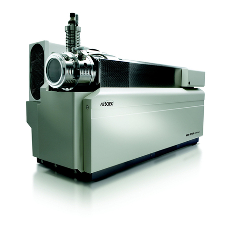
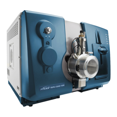
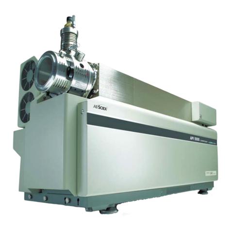
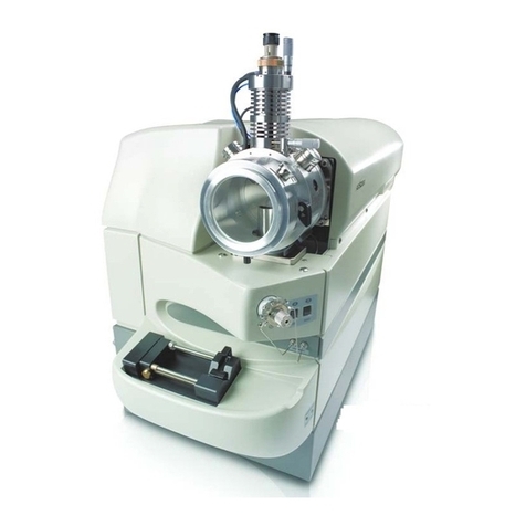
AB Sciex 4500 Series User manual

AB SCIEX 4500 Series of Instruments
System User Guide
Document Number: D5030863 A
Release Date: March 2012

AB SCIEX
71 Four Valley Dr., Concord, Ontario, Canada. L4K 4V8.
AB Sciex LP is ISO 9001 registered.
© 2012 AB SCIEX.
Printed in Canada.
This document is provided to customers who have purchased
AB Sciex equipment to use in the operation of such AB Sciex
equipment. This document is copyright protected and any reproduction
of this document or any part of this document is strictly prohibited,
except as AB Sciex may authorize in writing.
Software that may be described in this document is furnished under a
license agreement. It is against the law to copy, modify, or distribute
the software on any medium, except as specifically allowed in the
license agreement. Furthermore, the license agreement may prohibit
the software from being disassembled, reverse engineered, or
decompiled for any purpose.
Portions of this document may make reference to other manufacturers
and/or their products, which may contain parts whose names are
registered as trademarks and/or function as trademarks of their
respective owners. Any such use is intended only to designate those
manufacturers' products as supplied by AB Sciex for incorporation into
its equipment and does not imply any right and/or license to use or
permit others to use such manufacturers' and/or their product names
as trademarks.
AB Sciex makes no warranties or representations as to the fitness of
this equipment for any particular purpose and assumes no
responsibility or contingent liability, including indirect or consequential
damages, for any use to which the purchaser may put the equipment
described herein, or for any adverse circumstances arising therefrom.
For research use only. Not for use in diagnostic procedures.
The trademarks mentioned herein are the property of
AB Sciex Pte. Ltd. or their respective owners.
AB SCIEX™ is being used under license.

System User Guide
Document Number: D5030863 A
4500 Series of Instruments
3 of 142
Contents
Chapter 1 Foreword . . . . . . . . . . . . . . . . . . . . . . . . . . . . . . . . . . . . . . . . . . . . . . . . . 7
General Safety Information . . . . . . . . . . . . . . . . . . . . . . . . . . . . . . . . . . . . . . . . . .7
Symbols and Conventions . . . . . . . . . . . . . . . . . . . . . . . . . . . . . . . . . . . . . . . . . .7
Qualified Personnel . . . . . . . . . . . . . . . . . . . . . . . . . . . . . . . . . . . . . . . . . . . . . . . .8
Equipment Use and Modification . . . . . . . . . . . . . . . . . . . . . . . . . . . . . . . . . . . . .8
Shipping Labels . . . . . . . . . . . . . . . . . . . . . . . . . . . . . . . . . . . . . . . . . . . . . . . . . . .9
Regulatory Compliance . . . . . . . . . . . . . . . . . . . . . . . . . . . . . . . . . . . . . . . . . . . . .9
Australia and New Zealand . . . . . . . . . . . . . . . . . . . . . . . . . . . . . . . . . . . . . . . .9
Canada . . . . . . . . . . . . . . . . . . . . . . . . . . . . . . . . . . . . . . . . . . . . . . . . . . . . . . .9
Europe . . . . . . . . . . . . . . . . . . . . . . . . . . . . . . . . . . . . . . . . . . . . . . . . . . . . . . .10
United States . . . . . . . . . . . . . . . . . . . . . . . . . . . . . . . . . . . . . . . . . . . . . . . . . .10
International . . . . . . . . . . . . . . . . . . . . . . . . . . . . . . . . . . . . . . . . . . . . . . . . . . .10
Symbols and Labels on the Mass Spectrometer . . . . . . . . . . . . . . . . . . . . . . . . .10
Occupational Health and Safety Symbols . . . . . . . . . . . . . . . . . . . . . . . . . . . . . .12
Mains Supply . . . . . . . . . . . . . . . . . . . . . . . . . . . . . . . . . . . . . . . . . . . . . . . . . . . .14
Laboratory Ventilation . . . . . . . . . . . . . . . . . . . . . . . . . . . . . . . . . . . . . . . . . . . . .14
Environmental Conditions . . . . . . . . . . . . . . . . . . . . . . . . . . . . . . . . . . . . . . . . . .14
Instrument Disposal (Waste Electrical and Electronic Equipment) . . . . . . . . . . .15
Chapter 2 System Information . . . . . . . . . . . . . . . . . . . . . . . . . . . . . . . . . . . . . . . 17
Theory of Operation . . . . . . . . . . . . . . . . . . . . . . . . . . . . . . . . . . . . . . . . . . . . . .17
Data Handling . . . . . . . . . . . . . . . . . . . . . . . . . . . . . . . . . . . . . . . . . . . . . . . . .17
System Overview . . . . . . . . . . . . . . . . . . . . . . . . . . . . . . . . . . . . . . . . . . . . . . . .17
Instrument Panel Symbols . . . . . . . . . . . . . . . . . . . . . . . . . . . . . . . . . . . . . . . . .20
Turn on the System . . . . . . . . . . . . . . . . . . . . . . . . . . . . . . . . . . . . . . . . . . . . . . .20
Reset the System . . . . . . . . . . . . . . . . . . . . . . . . . . . . . . . . . . . . . . . . . . . . . . . .21
Shut Down the System . . . . . . . . . . . . . . . . . . . . . . . . . . . . . . . . . . . . . . . . . . . .21
Edit the Hardware Profile for the Integrated Syringe Pump . . . . . . . . . . . . . . . .22
Adjust the Integrated Syringe Pump Position . . . . . . . . . . . . . . . . . . . . . . . . . . .22
Configure the Integrated Syringe Pump . . . . . . . . . . . . . . . . . . . . . . . . . . . . . . .25
Configure the Diverter Valve . . . . . . . . . . . . . . . . . . . . . . . . . . . . . . . . . . . . . . . .25
Plumb the Diverter Valve . . . . . . . . . . . . . . . . . . . . . . . . . . . . . . . . . . . . . . . . . .26
Plumb the Diverter Valve in Injector Mode . . . . . . . . . . . . . . . . . . . . . . . . . . .26
Plumb the Diverter Valve in Diverter Mode . . . . . . . . . . . . . . . . . . . . . . . . . . .29
Instrument Safe Fluids . . . . . . . . . . . . . . . . . . . . . . . . . . . . . . . . . . . . . . . . . . . .30
Chapter 3 Hardware Profiles and Projects . . . . . . . . . . . . . . . . . . . . . . . . . . . . . 31
Hardware Profiles . . . . . . . . . . . . . . . . . . . . . . . . . . . . . . . . . . . . . . . . . . . . . . . .31
Create a Hardware Profile . . . . . . . . . . . . . . . . . . . . . . . . . . . . . . . . . . . . . . . . . .31
Add Devices to a Hardware Profile . . . . . . . . . . . . . . . . . . . . . . . . . . . . . . . . . . .34
Troubleshooting Hardware Profile Activation . . . . . . . . . . . . . . . . . . . . . . . . . . .35
Create Projects and Subprojects . . . . . . . . . . . . . . . . . . . . . . . . . . . . . . . . . . . .36
Create a Subproject . . . . . . . . . . . . . . . . . . . . . . . . . . . . . . . . . . . . . . . . . . . . . .37
Copy a Subproject . . . . . . . . . . . . . . . . . . . . . . . . . . . . . . . . . . . . . . . . . . . . . . . .37
Installed Project Folders . . . . . . . . . . . . . . . . . . . . . . . . . . . . . . . . . . . . . . . . . . .37

Contents
4500 Series of Instruments
4 of 142
System User Guide
Document Number: D5030863 A
Back up the API Instrument Folder . . . . . . . . . . . . . . . . . . . . . . . . . . . . . . . . . . .38
Chapter 4 Instrument Tuning and Calibrating. . . . . . . . . . . . . . . . . . . . . . . . . . . 39
Required material . . . . . . . . . . . . . . . . . . . . . . . . . . . . . . . . . . . . . . . . . . . . . .39
Prerequisites . . . . . . . . . . . . . . . . . . . . . . . . . . . . . . . . . . . . . . . . . . . . . . . . . .39
Optimize the Instrument . . . . . . . . . . . . . . . . . . . . . . . . . . . . . . . . . . . . . . . . . . .39
Verify or Adjust Performance . . . . . . . . . . . . . . . . . . . . . . . . . . . . . . . . . . . . . .40
Results Summary . . . . . . . . . . . . . . . . . . . . . . . . . . . . . . . . . . . . . . . . . . . . . .40
Chapter 5 Basic Acquisition Methods . . . . . . . . . . . . . . . . . . . . . . . . . . . . . . . . . 43
Create Acquisition Methods . . . . . . . . . . . . . . . . . . . . . . . . . . . . . . . . . . . . . . . .43
Add an Experiment . . . . . . . . . . . . . . . . . . . . . . . . . . . . . . . . . . . . . . . . . . . . .43
Add a Period . . . . . . . . . . . . . . . . . . . . . . . . . . . . . . . . . . . . . . . . . . . . . . . . . .43
Copy an Experiment into a Period . . . . . . . . . . . . . . . . . . . . . . . . . . . . . . . . . .44
Copy an Experiment within a Period . . . . . . . . . . . . . . . . . . . . . . . . . . . . . . . .44
Scan Techniques . . . . . . . . . . . . . . . . . . . . . . . . . . . . . . . . . . . . . . . . . . . . . . . .44
Quadrupole-Mode Scan Types . . . . . . . . . . . . . . . . . . . . . . . . . . . . . . . . . . . .44
LIT-Mode Scan Types . . . . . . . . . . . . . . . . . . . . . . . . . . . . . . . . . . . . . . . . . . .45
About Spectral Data Acquisition . . . . . . . . . . . . . . . . . . . . . . . . . . . . . . . . . . .46
Parameters . . . . . . . . . . . . . . . . . . . . . . . . . . . . . . . . . . . . . . . . . . . . . . . . . . . . .46
Acquisition Method Editor Icons . . . . . . . . . . . . . . . . . . . . . . . . . . . . . . . . . . . . .53
Chapter 6 Batches . . . . . . . . . . . . . . . . . . . . . . . . . . . . . . . . . . . . . . . . . . . . . . . . . 55
Set Queue Options . . . . . . . . . . . . . . . . . . . . . . . . . . . . . . . . . . . . . . . . . . . . . . .55
Create and Submit a Batch . . . . . . . . . . . . . . . . . . . . . . . . . . . . . . . . . . . . . . . . .56
Change Sample Order . . . . . . . . . . . . . . . . . . . . . . . . . . . . . . . . . . . . . . . . . . . .58
Acquire Data . . . . . . . . . . . . . . . . . . . . . . . . . . . . . . . . . . . . . . . . . . . . . . . . . . . .58
Set Sample Locations in the Batch Editor . . . . . . . . . . . . . . . . . . . . . . . . . . . . . .59
Select Vial Positions using the Locations Tab . . . . . . . . . . . . . . . . . . . . . . . . . .59
Stop Sample Acquisition . . . . . . . . . . . . . . . . . . . . . . . . . . . . . . . . . . . . . . . . . . .61
Batch and Acquisition Method Editor Tips . . . . . . . . . . . . . . . . . . . . . . . . . . . . .61
Batch Editor Right-Click Menu . . . . . . . . . . . . . . . . . . . . . . . . . . . . . . . . . . . . .62
Queue States and Device Status . . . . . . . . . . . . . . . . . . . . . . . . . . . . . . . . . . . .62
Queue States . . . . . . . . . . . . . . . . . . . . . . . . . . . . . . . . . . . . . . . . . . . . . . . . . .63
View Instrument and Device Status Icons . . . . . . . . . . . . . . . . . . . . . . . . . . . .64
Queue Right-Click Menu . . . . . . . . . . . . . . . . . . . . . . . . . . . . . . . . . . . . . . . . .65
Chapter 7 Analyzing and Processing Data . . . . . . . . . . . . . . . . . . . . . . . . . . . . . 69
Open Data Files . . . . . . . . . . . . . . . . . . . . . . . . . . . . . . . . . . . . . . . . . . . . . . . .69
Navigate Between Samples in a Data File . . . . . . . . . . . . . . . . . . . . . . . . . . .69
Show Experimental Conditions . . . . . . . . . . . . . . . . . . . . . . . . . . . . . . . . . . . .70
Show Data in Tables . . . . . . . . . . . . . . . . . . . . . . . . . . . . . . . . . . . . . . . . . . . .70
Show ADC Data . . . . . . . . . . . . . . . . . . . . . . . . . . . . . . . . . . . . . . . . . . . . . . .72
Show Basic Quantitative Data . . . . . . . . . . . . . . . . . . . . . . . . . . . . . . . . . . . . .72
Chromatograms . . . . . . . . . . . . . . . . . . . . . . . . . . . . . . . . . . . . . . . . . . . . . . . . .73
Show TICs from a Spectrum . . . . . . . . . . . . . . . . . . . . . . . . . . . . . . . . . . . . . .73
Show a Spectrum from a TIC . . . . . . . . . . . . . . . . . . . . . . . . . . . . . . . . . . . . .74
Generate XICs . . . . . . . . . . . . . . . . . . . . . . . . . . . . . . . . . . . . . . . . . . . . . . . . .74
Generate BPCs . . . . . . . . . . . . . . . . . . . . . . . . . . . . . . . . . . . . . . . . . . . . . . . .76
Generate XWCs . . . . . . . . . . . . . . . . . . . . . . . . . . . . . . . . . . . . . . . . . . . . . . .77

Contents
System User Guide
Document Number: D5030863 A
4500 Series of Instruments
5 of 142
Show DAD Data . . . . . . . . . . . . . . . . . . . . . . . . . . . . . . . . . . . . . . . . . . . . . . .78
Generate TWCs . . . . . . . . . . . . . . . . . . . . . . . . . . . . . . . . . . . . . . . . . . . . . . . .78
Adjust the Threshold . . . . . . . . . . . . . . . . . . . . . . . . . . . . . . . . . . . . . . . . . . . .79
Data Processing . . . . . . . . . . . . . . . . . . . . . . . . . . . . . . . . . . . . . . . . . . . . . . . . .80
Graphs . . . . . . . . . . . . . . . . . . . . . . . . . . . . . . . . . . . . . . . . . . . . . . . . . . . . . . .81
Zoom in on the y-axis . . . . . . . . . . . . . . . . . . . . . . . . . . . . . . . . . . . . . . . . . . .82
Zoom in on the x-axis . . . . . . . . . . . . . . . . . . . . . . . . . . . . . . . . . . . . . . . . . . .82
Chapter 8 Analyzing and Processing Quantitative Data . . . . . . . . . . . . . . . . . . 85
Quantitative Analysis . . . . . . . . . . . . . . . . . . . . . . . . . . . . . . . . . . . . . . . . . . . . . .85
Quantitation Methods . . . . . . . . . . . . . . . . . . . . . . . . . . . . . . . . . . . . . . . . . . .85
About Results Tables . . . . . . . . . . . . . . . . . . . . . . . . . . . . . . . . . . . . . . . . . . .86
Quantitation Methods and Results Tables . . . . . . . . . . . . . . . . . . . . . . . . . . . .86
Create a Method using the Quantitation Method Editor . . . . . . . . . . . . . . . . .86
Create a Results Table using the Quantitation Wizard . . . . . . . . . . . . . . . . . .87
Create a Standard Query . . . . . . . . . . . . . . . . . . . . . . . . . . . . . . . . . . . . . . . .88
Results Table Right-Click Menu . . . . . . . . . . . . . . . . . . . . . . . . . . . . . . . . . . .90
Peak Review and Manual Integration of Peaks . . . . . . . . . . . . . . . . . . . . . . . . .91
Review Peaks . . . . . . . . . . . . . . . . . . . . . . . . . . . . . . . . . . . . . . . . . . . . . . . . .92
Manually Integrate Peaks . . . . . . . . . . . . . . . . . . . . . . . . . . . . . . . . . . . . . . . .95
Peak Review Right-Click Menu . . . . . . . . . . . . . . . . . . . . . . . . . . . . . . . . . . . .96
Calibration Curves . . . . . . . . . . . . . . . . . . . . . . . . . . . . . . . . . . . . . . . . . . . . . . . .97
View Calibration Curves . . . . . . . . . . . . . . . . . . . . . . . . . . . . . . . . . . . . . . . . .98
Overlay Calibration Curves . . . . . . . . . . . . . . . . . . . . . . . . . . . . . . . . . . . . . . .99
Calibration Curve Right-Click Menu . . . . . . . . . . . . . . . . . . . . . . . . . . . . . . . .99
Sample Statistics . . . . . . . . . . . . . . . . . . . . . . . . . . . . . . . . . . . . . . . . . . . . . . . .100
View the Statistics for Standards and Qcs . . . . . . . . . . . . . . . . . . . . . . . . . .100
Compare Results Between Batches . . . . . . . . . . . . . . . . . . . . . . . . . . . . . . .101
Appendix A Turbo V™ Ion Source User Reference . . . . . . . . . . . . . . . . . . . . . .105
Introduction to the Ion Source . . . . . . . . . . . . . . . . . . . . . . . . . . . . . . . . . . . . . .105
Probes . . . . . . . . . . . . . . . . . . . . . . . . . . . . . . . . . . . . . . . . . . . . . . . . . . . . . .106
Gas and Electrical Connections . . . . . . . . . . . . . . . . . . . . . . . . . . . . . . . . . .108
Ion Source Latch . . . . . . . . . . . . . . . . . . . . . . . . . . . . . . . . . . . . . . . . . . . . . .108
Source Exhaust System . . . . . . . . . . . . . . . . . . . . . . . . . . . . . . . . . . . . . . . .108
Installation . . . . . . . . . . . . . . . . . . . . . . . . . . . . . . . . . . . . . . . . . . . . . . . . . . . . .109
Install the Ion Source . . . . . . . . . . . . . . . . . . . . . . . . . . . . . . . . . . . . . . . . . . .109
Optimization . . . . . . . . . . . . . . . . . . . . . . . . . . . . . . . . . . . . . . . . . . . . . . . . . . .111
Optimize the TurboIonSpray®Probe . . . . . . . . . . . . . . . . . . . . . . . . . . . . . . .111
Optimize the APCI Probe . . . . . . . . . . . . . . . . . . . . . . . . . . . . . . . . . . . . . . .114
Maintenance . . . . . . . . . . . . . . . . . . . . . . . . . . . . . . . . . . . . . . . . . . . . . . . . . . .116
Clean the Probes . . . . . . . . . . . . . . . . . . . . . . . . . . . . . . . . . . . . . . . . . . . . . .116
Remove the Ion Source . . . . . . . . . . . . . . . . . . . . . . . . . . . . . . . . . . . . . . . . .117
Remove the Probe . . . . . . . . . . . . . . . . . . . . . . . . . . . . . . . . . . . . . . . . . . . . .117
Clean the Electrode Tube . . . . . . . . . . . . . . . . . . . . . . . . . . . . . . . . . . . . . . .118
Adjust the Electrode Tip Extension . . . . . . . . . . . . . . . . . . . . . . . . . . . . . . . .119
Replace the Corona Discharge Needle . . . . . . . . . . . . . . . . . . . . . . . . . . . . .120
Replace the Sample Tubing . . . . . . . . . . . . . . . . . . . . . . . . . . . . . . . . . . . . .121
Troubleshooting . . . . . . . . . . . . . . . . . . . . . . . . . . . . . . . . . . . . . . . . . . . . . . . .122
Consumables . . . . . . . . . . . . . . . . . . . . . . . . . . . . . . . . . . . . . . . . . . . . . . . . . .123

Contents
4500 Series of Instruments
6 of 142
System User Guide
Document Number: D5030863 A
Appendix B 4500 Series Instrument Requirements and Parameters . . . . . . . .125
Electrical and Gas Requirements . . . . . . . . . . . . . . . . . . . . . . . . . . . . . . . . . . .125
Instrument Parameters . . . . . . . . . . . . . . . . . . . . . . . . . . . . . . . . . . . . . . . . . . .125
Appendix C Calibration Ions and Solutions . . . . . . . . . . . . . . . . . . . . . . . . . . . .131
Appendix D Cleaning and Maintenance . . . . . . . . . . . . . . . . . . . . . . . . . . . . . . .133
Health and Safety Precautions . . . . . . . . . . . . . . . . . . . . . . . . . . . . . . . . . . . . .133
Surface Cleaning . . . . . . . . . . . . . . . . . . . . . . . . . . . . . . . . . . . . . . . . . . . . . . . .134
Empty the Drain Bottle . . . . . . . . . . . . . . . . . . . . . . . . . . . . . . . . . . . . . . . . . . .134
Front-End Cleaning . . . . . . . . . . . . . . . . . . . . . . . . . . . . . . . . . . . . . . . . . . . . . .135
Best Practices . . . . . . . . . . . . . . . . . . . . . . . . . . . . . . . . . . . . . . . . . . . . . . . .136
Prepare for Routine Cleaning . . . . . . . . . . . . . . . . . . . . . . . . . . . . . . . . . . . .137
Clean the Curtain Plate . . . . . . . . . . . . . . . . . . . . . . . . . . . . . . . . . . . . . . . . .138
Clean the Front of the Orifice Plate . . . . . . . . . . . . . . . . . . . . . . . . . . . . . . . .139
Put the Instrument Back into Service . . . . . . . . . . . . . . . . . . . . . . . . . . . . . . . .139
Appendix E Basic System Troubleshooting . . . . . . . . . . . . . . . . . . . . . . . . . . .141

System User Guide
Document Number: D5030863 A
4500 Series of Instruments
7 of 142
Foreword
This foreword contains general safety-related information, describes the symbols and
conventions used in the documentation, and provides regulatory compliance information. It also
describes potential hazards and associated warnings for the system, and the precautions that
should be taken to minimize the hazards. In addition to this foreword, refer to the Site Planning
Guide for site requirements, including mains supply, source exhaust, ventilation, compressed air,
nitrogen and the roughing pump.
General Safety Information
Before operating any instrument, become familiar with its operation and with the potential
hazards. To prevent personal injury or instrument damage, read, understand, and obey all safety
precautions. Warnings in this document and labels on the mass spectrometer are shown with
international symbols. Failure to heed these warnings could result in serious injury.
This safety information is intended to supplement federal, state or provincial, and local
environmental health and safety (EHS) regulations. The information provided covers instrument-
related safety with regard to the operation of the mass spectrometer. It does not cover every
safety procedure that should be practised. Ultimately, you and your organization are responsible
for compliance with federal, state or provincial, and local EHS regulations and for maintaining a
safe laboratory environment.
For more information, refer to the appropriate laboratory reference material and standard
operating procedures.
Symbols and Conventions
The following conventions are used throughout the guide.
DANGER! Danger signifies an action which leads to severe injury or death.
WARNING! Personal Injury Hazard: A warning indicates an operation that could
cause personal injury if precautions are not followed.
WARNING! Electric Shock Hazard: This symbol indicates a warning of electrical
shock hazard. Read the warning and follow all precautions before performing any
operation described in the guide. Failure to do so can result in serious injury.
WARNING! Burn Hazard: This symbol indicates a warning of potential burns
from hot surfaces. Read the warning and follow all precautions before performing
any operation described in the guide. Failure to do so can result in serious injury.

Foreword
4500 Series of Instruments
8 of 142
System User Guide
Document Number: D5030863 A
Caution: A caution indicates an operation that could cause damage to the instrument or
loss of data if precautions are not followed.
Qualified Personnel
After installing the system, the FSE (Field Service Employee) uses the Customer Familiarization
Checklist to train the customer on system operation, cleaning, and basic maintenance. Only
qualified AB SCIEX personnel shall install and service the equipment. Only personnel qualified
by AB SCIEX shall operate and maintain the equipment. Contact an AB SCIEX FSE for more
information.
Equipment Use and Modification
Use the system indoors in a laboratory that complies with the environmental conditions
recommended in the system Site Planning Guide. If the system is used in an environment or in a
manner not prescribed by AB SCIEX, the protection provided by the equipment can be impaired.
Unauthorized modification or operation of the system may cause personal injury and equipment
damage, and may void the warranty. Erroneous data may be generated if operating the
instrument while exceeding the recommended environmental conditions or operating with
unauthorized modifications. Contact an AB SCIEX representative for more information on
servicing the instrument.
WARNING! Biohazard: This symbol indicates a warning of biohazardous
materials. Read the warning and follow all precautions before performing any
operation described in the guide. Failure to do so can result in serious injury.
Tip! Provides useful information that helps apply the techniques and procedures in
the text for a specific need, and provides shortcuts, but is not essential to the completion
of a procedure.
i
Note: A note emphasizes significant information in a procedure or description.

Foreword
System User Guide
Document Number: D5030863 A
4500 Series of Instruments
9 of 142
Shipping Labels
Regulatory Compliance
This system complies with the standards and regulations listed in this section. Applicable labels
have been affixed to the system.
Australia and New Zealand
•Electromagnetic Interference—AS/NZ CISPR 11 (Class A)
•Safety—AS/NZ 61010-1
Canada
•Electromagnetic Interference—CAN/CSA CISPR11. This ISM device complies
with Canadian ICES-001.
Table 1-1 Labels on the Crate
External Labels Definition Action
or
TIP N TELL
Blue beads in the arrow
indicate that the container was
tipped or mishandled.
Write on the Bill of Lading and
check for damage. Any claims
for tipping require a notation.

Foreword
4500 Series of Instruments
10 of 142
System User Guide
Document Number: D5030863 A
•Safety—CAN/CSA C22.2 No. 61010-1, and CAN/CSA C22.2 No. 61010-2-061
Europe
•Electromagnetic Compatibility—EN 55011 (Class A), EN 61326-1
•Safety—EN 61010-1, EN 61010-2-061
•WEEE—2002/96/EEC
United States
•Electromagnetic Interference, FCC Part 15, Class A—This equipment has been
tested and found to comply with the limits for a Class A digital device, pursuant to
Part 15 of the FCC (Federal Communications Commission Compliance) Rules.
These limits are designed to provide reasonable protection against harmful
interference when the equipment is operated in a commercial environment. This
equipment generates, uses, and can radiate radio frequency energy and, if not
installed and used in accordance with the operator’s manual, can cause harmful
interference to radio communications. Operation of this equipment in a residential
area is likely to cause harmful interference in which case you will be required to
correct the interference, at your own expense. Changes or modifications not
expressly approved by the manufacturer could void your authority to operate the
equipment.
•Safety—UL 61010-1, IEC 61010-2-061
International
•Electromagnetic Compatibility—IEC 61326-1, IEC CISPR 11 Class A
•Safety—IEC 61010-1, IEC 61010-2-061
For more information, see the Declaration of Conformance included with the system.
Symbols and Labels on the Mass Spectrometer
Table 1-2 Labels on the Mass Spectrometer
External Labels Definition
WARNING: NO USER SERVICEABLE PARTS
INSIDE. REFER SERVICING TO QUALIFIED
PERSONNEL.
EN61326—1:2006 CLASS A, GROUP 1, ISM
EQUIPMENT

Foreword
System User Guide
Document Number: D5030863 A
4500 Series of Instruments
11 of 142
This ISM device complies with Canadian ICES-001.
Cet appareil ISM est conforme à la norme NMB-001
du Canada.
FCC Compliance. This device complies with Part 15
of the FCC Rules. Operation is subject to the
following conditions: (1) this device may not cause
harmful interference, and (2) this device must accept
any interference received, including interference that
may cause undesired operation.
0211-3199
Do not dispose of equipment as unsorted municipal
waste (WEEE).
FOR RESEARCH USE ONLY. NOT FOR USE
IN DIAGNOSTIC PROCEDURES.
This instrument is for research use only. It is not
intended for use in diagnostic procedures.
Caution, see accompanying documents.
Minimum of 6 persons required to safely lift this
equipment
WARNING: Hot Surface Hazard.
Operator Guide
Follow operating instructions (mandatory)
Alternating Current
AAmperes (current)
Table 1-2 Labels on the Mass Spectrometer (Continued)
External Labels Definition

Foreword
4500 Series of Instruments
12 of 142
System User Guide
Document Number: D5030863 A
Occupational Health and Safety Symbols
This section describes some occupational health and safety symbols found in the laboratory
environment.
High voltage. Electrical Shock Hazard
On (Mains supply)
Off (Mains supply)
Protective Earth (ground)
VVolts (voltage)
V-A Volts - Amperes (power)
WWatts (power)
Table 1-3 Chemical Hazard Symbols
Safety Symbol Description
Biohazard
Corrosive or Caustic Chemical Hazard
Explosion Hazard
Oxidizing Chemical Hazard
Poison Hazard
Reactive Chemical Hazard
Table 1-2 Labels on the Mass Spectrometer (Continued)
External Labels Definition

Foreword
System User Guide
Document Number: D5030863 A
4500 Series of Instruments
13 of 142
Toxic Chemical Hazard
Table 1-4 Mechanical Hazard Symbols
Safety Symbol Description
Automated Machinery Hazard
Crushing Hazard — From Above
Crushing Hazard — From Side
Fire Hazard
Hot Surface Hazard
Laser Radiation Hazard
Lifting Hazard
Magnetic Hazard
Puncture Hazard
Table 1-5 Pressurized Gas Hazard Warning Symbols
Safety Symbol Description
Pressurized Gas Hazard
Table 1-3 Chemical Hazard Symbols (Continued)
Safety Symbol Description

Foreword
4500 Series of Instruments
14 of 142
System User Guide
Document Number: D5030863 A
Mains Supply
The total combined system (instrument and roughing pump) power consumption is 2200 VA (50
or 60 Hz) at 230 VAC.
An external line transformer is not needed for the instrument, optional bench, or roughing pump.
Caution: Do not unpack or connect any components. The AB SCIEX FSE will unpack,
connect, and configure the system for the proper operating voltage.
For information on system electrical specifications, refer to the Site Planning Guide.
Protective Conductor
The mains supply should include a correctly installed protective earth conductor that must be
installed or checked by a qualified electrician before connecting the instrument.
Do not intentionally interrupt the protective conductor. Any interruption of the protective
conductor is likely to make the installation dangerous.
Laboratory Ventilation
The venting of fumes and disposal of waste must be in accordance with all federal, state,
provincial, and local health and safety regulations. The instrument shall be used indoors in a
laboratory that complies with the environmental conditions recommended in the Site Planning
Guide for the instrument. The source exhaust system must be vented either to an external fume
hood or to an external exhaust system as recommended in the Site Planning Guide for the
instrument.
Environmental Conditions
Use qualified personnel for the installation of electrical mains, heating, ventilation, and plumbing
supplies and fixtures. Make sure that all installations follow local bylaws and biohazard
regulations. For more information about the required environmental conditions for the system,
refer to the Site Planning Guide for the instrument.
WARNING! Electrical Shock Hazard: Use only qualified personnel for the
installation of all electrical supplies and fixtures, and make sure that all
installations adhere to local regulations.
DANGER! Explosion Hazard: The instrument is not designed for operation in an
explosive environment. Do not operate the instrument in an environment
containing explosive gases.

Foreword
System User Guide
Document Number: D5030863 A
4500 Series of Instruments
15 of 142
Instrument Disposal (Waste Electrical and
Electronic Equipment)
Do not dispose of system components or subassemblies, including computer parts, as unsorted
municipal waste. Follow local municipal waste ordinances for proper disposal provisions to
reduce the environmental impact of WEEE (waste, electrical, and electronic equipment). To
make sure that you safely dispose of this equipment, contact an FSE for instructions.
European Union customers: Contact a local AB SCIEX Customer Service office for
complimentary equipment pick-up and recycling.
WARNING! Asphyxiation Hazard: The use of instruments without adequate
ventilation to outside air may constitute a health hazard. In addition, certain
procedures required during the operation of the instrument may cause gases to
be discharged into the exhaust stream; under these conditions, inadequate
ventilation may result in serious injury. Take extreme care to vent exhaust gases
properly.
WARNING! Toxic Chemical Hazard: Make sure the mass spectrometer system is
connected to the local exhaust system and ducted to control hazardous
emissions. The mass spectrometer system should only be used in a well-
ventilated laboratory environment in compliance with local regulations and with
appropriate air exchange for the work performed.
Note: In the USA, OSHA 29 CFR Part 1910-1450 requires 4 to12 air changes per hour
in laboratories.
WARNING! Biohazard: This instrument or any part is not intended to act as a
biological containment safety cabinet. For biohazardous material use, always
apply local regulations for hazard assessment, control, and handling.

Foreword
4500 Series of Instruments
16 of 142
System User Guide
Document Number: D5030863 A

System User Guide
Document Number: D5030863 A
4500 Series of Instruments
17 of 142
2
System Information
The 4500 series of instruments are intended for the qualitative and quantitative analysis of
chemical species. The system includes a mass spectrometer, a Turbo V™ ion source, a
computer, and the Analyst®software.
Theory of Operation
Mass spectrometry measures the mass-to-charge ratio of ions to identify unknown compounds,
to quantify known compounds, and to provide information about the structural and chemical
properties of molecules.
The 4500 series of instruments have a series of quadrupole filters that transmit ions according to
their mass-to-charge (m/z) value. The first quadrupole in this series is the QJet Ion Guide located
between the orifice plate and Q0. The QJet Ion Guide does not filter ions, but focuses them
before they enter Q0. By prefocusing the larger ion flux created by the wider orifice, the QJet Ion
Guide increases instrument sensitivity and improves the signal-to-noise ratio. In Q0 the ions are
again focused before passing into Q1.
Q1 is a filtering quadrupole that sorts the ions before they enter Q2. Q2 is a collision cell in which
an ions internal energy is increased though collisions with gas molecules to the point that
molecular bonds break creating product ions. This technique allows users to design experiments
that measure the m/z of product ions to determine the composition of the parent ions.
After passing through Q2 the ions enter Q3 for additional filtering, and then enter the detector. In
the detector, the ions create a current that is converted into a voltage pulse. The voltage pulses
leaving the detector are directly proportional to the quantity of ions entering the detector. The
instrument monitors these voltage pulses and converts the information into a signal. The signal
represents the ion intensity for a particular m/z value and the instrument displays this formation
as a mass spectrum.
Data Handling
The Analyst software requires a computer running the Windows operating system. The computer
with the associated system software works with the system controller and associated firmware to
control the instrument and data acquisition. When operating the instrument, the acquired data is
sent to the Analyst software where it can be displayed as either full mass spectra, intensity of
single or multiple ions versus time, or total ion current versus time.
System Overview
Figure 2-1 Front View shows a system with a syringe pump, Turbo V ion source, a diverter valve,
and the optional NanoSpray®ion source monitors.

System Information
4500 Series of Instruments
18 of 142
System User Guide
Document Number: D5030863 A
Figure 2-2 Rear and Side Views on page 19 shows the location of the instrument connections,
including the locations of the reset and vent buttons and the instrument switch.
Figure 2-1 Front View
Item Description For more information refer to...
1 Instrument panel symbols Table 2-1 on page 20.
2 Nanospray ion source
monitors (optional)
NanoSpray®Ion Source Operator Guide located on the
DVD that comes with the ion source.
3 Syringe pump Adjust the Integrated Syringe Pump Position on
page 22.
4 Turbo V ion source Turbo V™ Ion Source User Reference
5 Diverter valve If the optional DuoSpray™ion source is installed, then
the diverter valve is replaced with the DuoSpray valve.
The diverter valve is installed below the DuoSpray
valve. Refer to Configure the Integrated Syringe Pump
on page 25.
For information about the DuoSpray ion source, refer to
the DuoSpray™ Ion Source Operator Guide located on
the DVD that comes with the ion source.
AB
AB
1
3
5
4
2

System Information
System User Guide
Document Number: D5030863 A
4500 Series of Instruments
19 of 142
Figure 2-2 Rear and Side Views
Item Description For more information...
1 Roughing pump vacuum connection Contact an AB SCIEX FSE.
2 Nitrogen gas supply (Curtain Gas™
supply, CAD gas)
Contact an AB SCIEX FSE.
3 Source exhaust supply Contact an AB SCIEX FSE.
4 Source communication connection Contact an AB SCIEX FSE.
5 Instrument reset button Refer to Reset the System on page 21.
6 Mains supply connection Refer to Turn on the System on page 20 or
Shut Down the System on page 21.
7 Instrument switch
(Up = On; Down = Off)
Refer to Turn on the System on page 20 or
Shut Down the System on page 21.
8 Aux I/O connection Refer to the Peripheral Devices Setup Guide.
9 Ethernet connection (connects the
instrument and the computer)
Contact an AB SCIEX FSE.
10 Instrument vent (shutdown) button Refer to Turn on the System on page 20 or
Shut Down the System on page 21.
11 Source exhaust waste (to waste
bottle)
Contact an AB SCIEX FSE.
AUX. I/O
VENT
R
E
S
E
T
7
5
12
3
12
11
9
6
8
4
10

System Information
4500 Series of Instruments
20 of 142
System User Guide
Document Number: D5030863 A
Instrument Panel Symbols
Table 2-1 shows the instrument status LEDs.
After the instrument is turned on, all five LEDs illuminate. The power LED remains lit. The other
four LEDs flash for two seconds and then turn off. The vacuum LED starts flashing. After the
correct vacuum has been achieved this LED remains lit.
Turn on the System
Before the system is turned on, make sure the site requirements specified in the Site Planning
Guide are met. This includes information on the mains supply and connections, source exhaust,
compressed air, nitrogen, roughing pump, ventilation, exhaust, and site clearance.
1. Make sure there is clear access to the power cord. The power cord must be
accessible in order to disconnect the instrument from the AC Mains.
2. Make sure the 4 L drain bottle is connected to the Exhaust Waste connection on the
rear of the instrument and to the laboratory ventilation system.
12 Air supply (Gas1/Gas2) Contact an AB SCIEX FSE.
Table 2-1 Instrument Panel Symbols
Instrument LEDs Color Name Description
Green Power Lit when the instrument is powered up.
Green Vacuum Lit when the correct vacuum has been
achieved; and flashing if the vacuum is
not at the correct vacuum (during
pumpdown and venting.)
Green Ready Lit when the instrument is in the Ready
state. Instrument must be in the Ready
state to operate.
Blue Scanning Flashing when the instrument is acquiring
data.
Red Fault Lit when the instrument encounters a
system fault.
WARNING! Personal Injury Hazard. Risk of personal injury or instrument
damage. If the system must be moved, contact a Field Service Employee.
Note: Before operating the instrument, read the safety information in the Foreword.
Figure 2-2 Rear and Side Views (Continued)
Item Description For more information...
Table of contents
Other AB Sciex Laboratory Equipment manuals
Popular Laboratory Equipment manuals by other brands

MS Schippers
MS Schippers MS Greenline mini manual

V&P Scientific
V&P Scientific 418SV2-2x4-50CB-CC operating instructions

THORLABS
THORLABS M780L3-C1 operating instructions

Powerfiller
Powerfiller Powermax 3+ user manual

Neuation
Neuation iSHAK QUATTRO NXT Product user manual

Basler
Basler BE1-25A instruction manual