NI USB-6509 User manual

USER GUIDE AND SPECIFICATIONS
NI USB-6509
This document contains information about using the National Instruments
USB-6509 data acquisition (DAQ) device with NI-DAQmx 8.7 and later.
The NI USB-6509 is a bus-powered 96-channel, digital input/output (I/O)
device. The NI USB-6509 features 96 TTL/CMOS-compatible digital I/O
lines, a watchdog timer, digital input filtering and change detection, and
output programmable power-up states. The NI USB-6509 also features an
optional external DC power supply that can increase the I/O drive strength.
Contents
Getting Started ........................................................................................ 2
Installing Software........................................................................... 2
Installing the Hardware.................................................................... 3
USB Cable Strain Relief .................................................................. 3
Mounting the NI USB-6509 ............................................................ 3
Desktop Use.............................................................................. 3
DIN Rail Mounting................................................................... 4
Panel Mounting......................................................................... 5
Hardware Overview ................................................................................ 6
Programming Devices in Software ......................................................... 7
Related Documentation.................................................................... 8
I/O Connector.......................................................................................... 8
Pin Assignments .............................................................................. 8
SH100-100-F Pin Assignments ................................................ 8
R1005050 Pin Assignments...................................................... 10
Signal Descriptions .......................................................................... 11
Digital I/O ............................................................................................... 12
Static DIO on NI USB-6509 Devices .............................................. 12
Digital I/O Circuitry......................................................................... 12
I/O Protection................................................................................... 12
I/O State at Power-On/Power-Off/Suspend..................................... 13
I/O Pull-Up/Pull-Down Resistor...................................................... 13
High DIO State ......................................................................... 13
Low DIO State.......................................................................... 14
Increasing Current Drive on NI USB-6509 Devices ....................... 15

NI 6509 User Guide and Specifications 2 ni.com
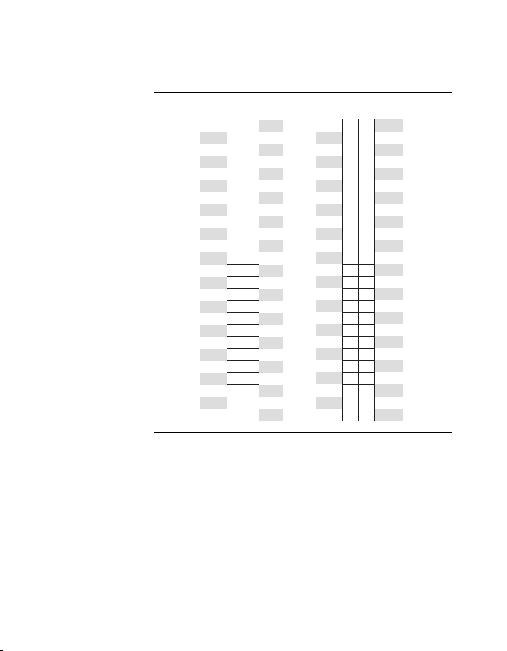
DIO Signal Connection ....................................................................16
Protecting Inductive Loads...............................................................17
Sinking and Sourcing Examples.......................................................17
Driving a Relay <24 mA ...........................................................17
Driving a Relay >24 mA ...........................................................18
Driving SSRs.............................................................................19
LED Indicator...................................................................................19
Power Connection....................................................................................19
Optional +12 VDC Power Supply Installation.................................19
+5 V Power Available at I/O Connector ..........................................20
Industrial DIO Features ...........................................................................20
Digital Filtering ................................................................................20
Digital Filtering Example..........................................................21
Programmable Power-Up States.......................................................22
Change Detection .............................................................................22
Change Detection Example.......................................................23
Watchdog Timer...............................................................................23
Cables and Accessories ...........................................................................24
Specifications...........................................................................................24
Safety Guidelines.....................................................................................29
Where to Go for Support .........................................................................31
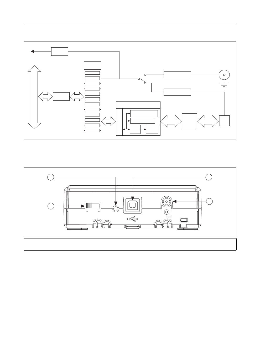
Getting Started
NI USB-6509 devices feature up to 96 bidirectional per-port static DIO
lines. If you have not already installed your device, refer to the NI-DAQmx
for USB Devices Getting Started Guide.
Before installing your DAQ device, you must install the software you plan
to use with the device.
Installing Software
Software support for the NI USB-6509 for Windows is provided by
NI-DAQmx.
The NI-DAQmx CD contains example programs that you can use to get
started programming with the NI USB-6509. Refer to the NI-DAQmx for
USB Devices Getting Started Guide, that shipped with your device and
is also accessible from Start»All Programs»National Instruments»
NI-DAQ,for more information.
Note For information about non-Windows operating system support, refer to
ni.com/info and enter rddqld.

©National Instruments Corporation 3 NI 6509 User Guide and Specifications
Installing the Hardware
The NI-DAQmx for USB Devices Getting Started Guide contains
non-software-specific information about how to install USB devices.
USB Cable Strain Relief
The two strain relief options for your USB cable are as follows:
•Cable Strain Relief Groove Method—Press the USB cable into one
of the two grooves on the underside of the NI USB-6509. Choose the
USB cable groove that matches your USB cable size, as shown in
Figure 1.
•Zip Tie Method—Thread a zip tie through the zip tie bar on the
underside of the NI USB-6509 and tighten around the USB cable,
as shown in Figure 1.
Figure 1. USB Cable Strain Relief Options
Mounting the NI USB-6509
You can use the NI USB-6509 on a desktop or mount it to a standard DIN
rail or a panel.
Desktop Use
You can use the NI USB-6509 on a desktop. The NI USB-6509 has grooves
on the underside that allow it to be stacked on top of other NI USB-6509
devices.
1 USB Cable Strain Relief Groove (Large)
2 USB Cable Strain Relief Groove (Small)
3 USB Cable
4 Zip Tie
5 Zip Tie Bar
3
4
1
2
3
5

NI 6509 User Guide and Specifications 4 ni.com
For secure desktop use, you can adhere the supplied rubber non-skid feet to
the underside of the device, as shown in Figure 2.
Note Do not apply the rubber feet if you are panel mounting the NI USB-6509 or stacking
multiple NI USB-6509 devices.
Figure 2. Applying Rubber Feet to the NI USB-6509
DIN Rail Mounting
The DIN rail mounting kit (part number 779689-01, not included in your
NI USB-6509 kit) is an accessory you can use to mount the NI USB-6509
to a standard DIN rail.
Note Apply strain relief, as described in the USB Cable Strain Relief section, before
mounting the NI USB-6509 to a DIN rail.

©National Instruments Corporation 5 NI 6509 User Guide and Specifications
Panel Mounting
To mount the NI USB-6509 to a board or panel, complete the following
steps while referring to Figure 3.
Figure 3. Mounting the NI USB-6509 on a Panel
Notes Do not apply the rubber feet to the NI USB-6509 when panel mounting the device.
Apply strain relief, as described in the USB Cable Strain Relief section, before panel
mounting the NI USB-6509.
1. Go to ni.com/info and enter the info code rd3233 to download and
print the panel mounting template PDF.
2. Using the template, mark the bottom point and top point on the panel.
The points will be 162 mm (6.375 in.) from each other.
3. Remove the USB cable from the connector on the NI USB-6509.
4. Screw a #8 or M4 screw into the bottom point on the panel.
5. Set the NI USB-6509 on the screw by fitting it into the bottom screw
notch on the underside of the NI USB-6509.
6. Screw a #8 or M4 screw through the NI USB-6509 top screw hole into
the panel.
Table of contents
Other NI Laboratory Equipment manuals
Popular Laboratory Equipment manuals by other brands

Belden
Belden HIRSCHMANN RPI-P1-4PoE installation manual

Koehler
Koehler K1223 Series Operation and instruction manual

Globe Scientific
Globe Scientific GCM-12 quick start guide

Getinge
Getinge 86 SERIES Technical manual

CORNING
CORNING Everon 6000 user manual

Biocomp
Biocomp GRADIENT MASTER 108 operating manual