Bion X G2 User manual

User ManUal

2

3
Welcome
Thank you for choosing BionX™. It is our goal to provide you with the highest quality elec-
tric propulsion systems available, and offer you the best possible after sales experience.
This document serves as a supplement to your bicycle user manual. Please read this manual
thoroughly, even if you are an experienced cyclist. Should you be unable to locate an answer
in the manual, please contact your dealer for immediate assistance.
We have always contended that a bike remain a bike. It is our love of cycling that drives us,
and a passion that we continue to share with our customers. We hope you enjoy your new
electric bicycle for many years to come.
If you ever have concerns or questions that your dealer cannot provide answers
to, or have comments relating to this user manual, feel free to contact us at

4
User Precautions
We want you to have a fun ride, but also a safe one. Carefully read the following information,
even if you are an experienced rider. Take the opportunity to familiarize yourself with your
BionX electric propulsion system before you take your first trip.
1. BionX recommends that you have your system installed professionally by an authorized dealer.
2. Read all of the enclosed installation and operating instructions from the manufacturer
and follow the instructions, if any, prior to its first use.
3. Familiarize yourself with your electric bicycle and the functions of the BionX system in a safe
environment before participating in road traffic for the first time.
4. Always wear a helmet when riding an electric bicycle for your own safety.
5. Make sure that the tires have the pressure recommended by the manufacturer before riding the bike.
6. Make sure that the brakes are operating properly before riding the bike.
7. Do not use a mobile phone or any other electronic devices while riding an electric bicycle; it is
imperative that you pay attention to traffic.
8. If possible, ride in bike lanes and always in the correct direction of traffic.
9. Adhere to all valid traffic regulations.
10. Keep in mind that other traffic participants may underestimate the speed of an electric bicycle.
11. Ride with both hands on the handlebars when riding your electric bicycle.
12. Ride as defensively as possible.
Enjoy your new BionX electric propulsion system!
Your BionX Team

5
Table of Contents
User Precautions 4
Description of the BionX SL Propulsion System 6
Description of the BionX PL Propulsion System 8
Inserting or Removing the Console 10
Inserting or Removing the Battery 11
Handling and Charging the Battery 12
Power supply 14
Chargers 15
Assist Mode / Generate Mode 16
Operating the BionX Propulsion System 17
Operating the G2 throttle 19
Programming the Basic Settings 20
Removing and Installing the Rear Wheel 21
Maintenance and Care 22
Cleaning 23
Transporting an Electric Bicycle on a Car 23
Repair and Spare Parts 23
Troubleshooting 24
Warranty Information and Guarantee 25

6
4
2a
1
3
Description of the BionX SL Propulsion System
1G2 Console
• Removable G2 console
• Illuminated LCD display with battery state of charge
•4assistancelevels
•4generatelevels
•Backlightandbicyclelightcontrols
•Offerscyclecomputerfunctions(speed,odometer,
clock, average speed, trip distance)
Remote throttle (where applicable)
•Assistance/GenerateToggle
•Variablecontrolthrottlelever
2a 48V Down Tube Battery
• LithiumManganese(LiMn)
• Removable, lockable
• Fully charged in: 4-5h
• Touch port state of charge indicator
• XL–48V/8.8Ah/423Wh
• L–48V/6.6Ah/317Wh(availableinEUonly)
2b 48V Rear Rack Battery
• LithiumManganese(LiMn)
• Removable, lockable
• Fully charged in: 4-5h
• Touch port state of charge indicator
• RRXL-48V/8.8Ah/423Wh
• RRL-48V/6.6Ah/317Wh(availableinEUonly)
2b
3
1
4
7
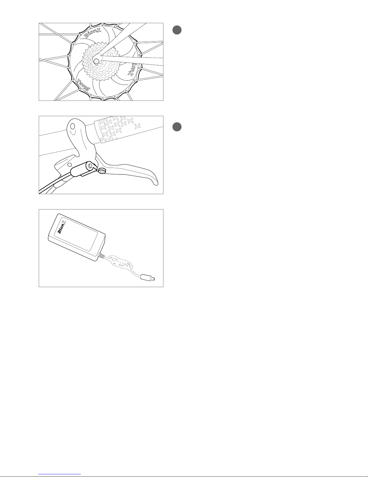
3SL Motor
• DCrear,hightorque(HT)hubmotor
• Nom.250W(EU),350W(NA)
• Nom.9Nm/max.40Nm(6.6/30lb-ft)
• 1.2Kg(2.6lb)lighterthanthe250HT(EU)/
350HT(NA)motor
• Brushless, gearless
• Generate mode for energy recuperation
• Integrated torque sensor
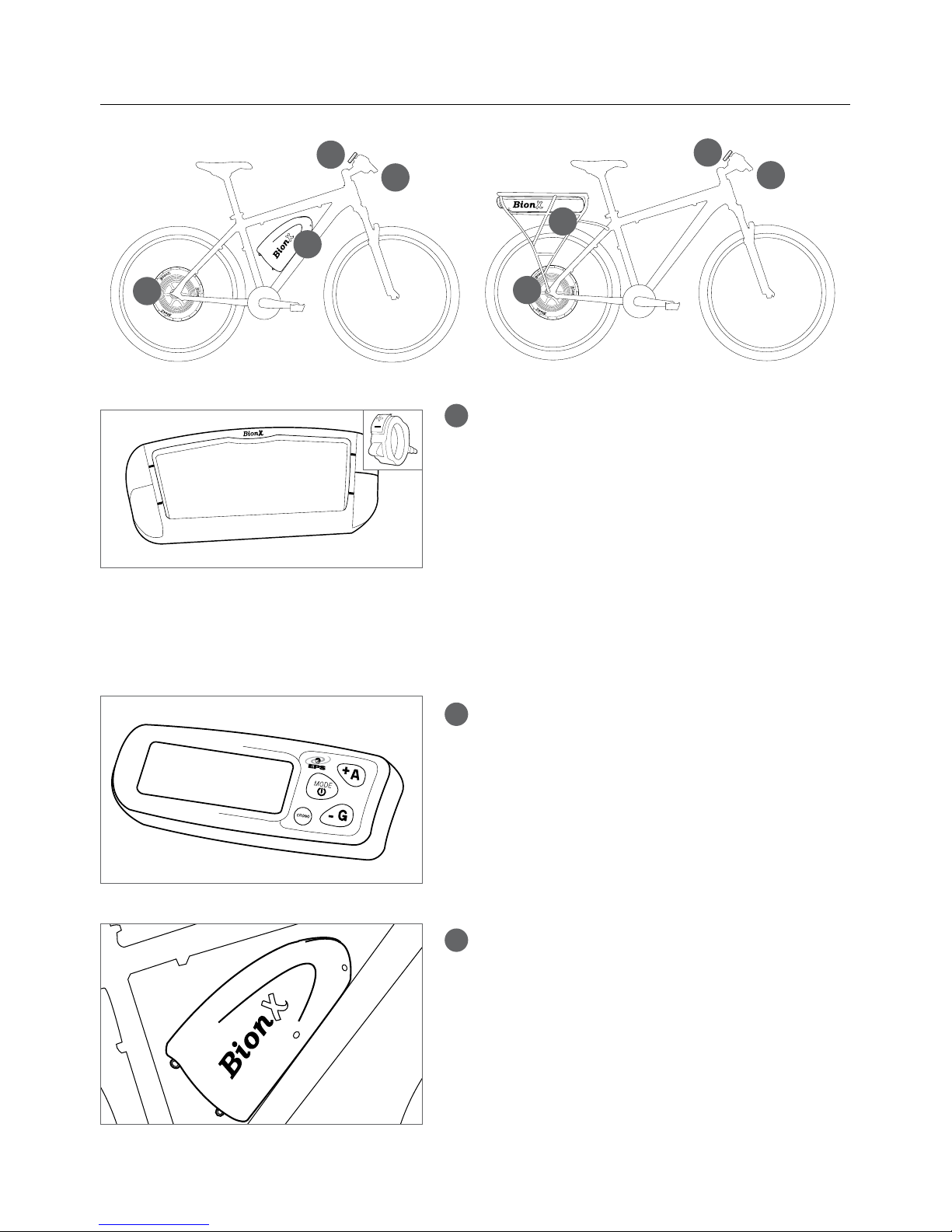
4Brake switch
• A surface mounted reed switch –
connected to the BionX console and magnet
• Uponactivationassistanceisshutoff(“killswitch”)
generate mode is activated
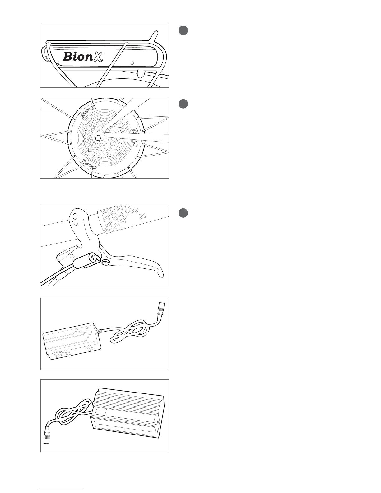
Power Supply
• Powersupplytorechargethe48VLiMnbattery
• Inputvoltage:100-240V
• Outputvoltage:26V
• Max. charge current: 3.45A
• Output:90W
8
Description of the BionX PL Propulsion System
1G2 Console (systems 2011 to present)
• Removable G2 console
• Illuminated LCD display with battery state of charge
•4assistancelevels
•4generatelevels
•Backlightandbicyclelightcontrols
•Offerscyclecomputerfunctions(speed,odometer,
clock, average speed, trip distance)
Remote throttle (where applicable)
•Assistance/GenerateToggle
•Variablecontrolthrottlelever
1G1 Console (systems 2010 and earlier)
• G1console(optionalthrottleleverwhereapplicable)
• Illuminated LCD display with battery state of charge
•4assistancelevels
•4generatelevels
•Backlightandbicyclelightcontrols
•Offerscyclecomputerfunctions(speed,odometer,
clock, average speed, trip distance)
2a 22.2, 26 or 37V Down Tube Battery
• LithiumManganese(LiMn)
• Removable, lockable
• Fully charged in: 4-5h
• L-37V/9.6Ah/355Wh
• M-26V/9.6Ah/250Wh
• S-22.2V/6.4Ah/142Wh
4
2a
1
3
2b
3
1
4
1
2
34
9
1
2
34
2b 37V Rear Rack Battery
• LithiumManganese(LiMn)
• Removable, lockable
• Fully charged in: 4-5h
• RRL-37V/9.6Ah/355Wh
• RRM-37V/6.4Ah/236Wh
3250, 250HT (EU) / 350HT (NA),
or 500* watt Motor
• DC rear hub motor
• 250W:nom.7Nm/max.25Nm(5/18.5lb-ft)
• 250HT(EU)/350HT(NA):
nom.9Nm/max.40Nm(6.6/30lb-ft)
• 500W:nom.9Nm/max.25Nm(6.6/18lb-ft)
• Brushless, gearless
• Generate mode for energy recuperation
• Integrated torque sensor
4Brake switch
• A surface mounted reed switch – connected to the
BionX console and magnet
• Uponactivationassistanceisshutoff(“killswitch”)
generate mode is activated
37V Single Light Battery Charger
(PL systems 2012 to present)
• Torechargethe37VLiMn-battery
• Inputvoltage:100-240V
• Outputvoltage:37V
• Max. charge current: 2A
22.2V, 26V or 37V Two Light Battery Charger
(PL systems 2011 and earlier)
• Torechargethe22.2V,26Vor37VLiMn-battery
• Inputvoltage:switchablebetween115-230V
• Outputvoltage:22.2V,26Vor37Vdepending
on model
• Max. charge current: 2A
*Note:the500wattmotorisnotlegalinallcountries.CheckwithyourlocalBionXdealerforlocallegislationand/oravaliability
10
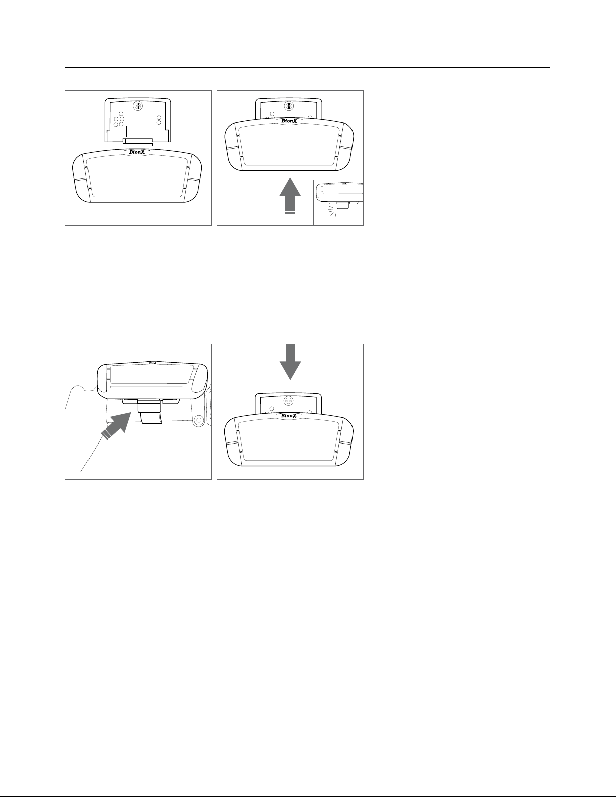
Inserting or Removing the Console
Inserting the console
• Slide the console into the console mount on the handlebar
• Makesurethattheconsoleengagessecurely.Wheninsertedcorrectly,youwillheara“click”
Removing the console
• Release the console by pushing the release lever on the console mount
• Slide the console out of the console mount
“click”
11
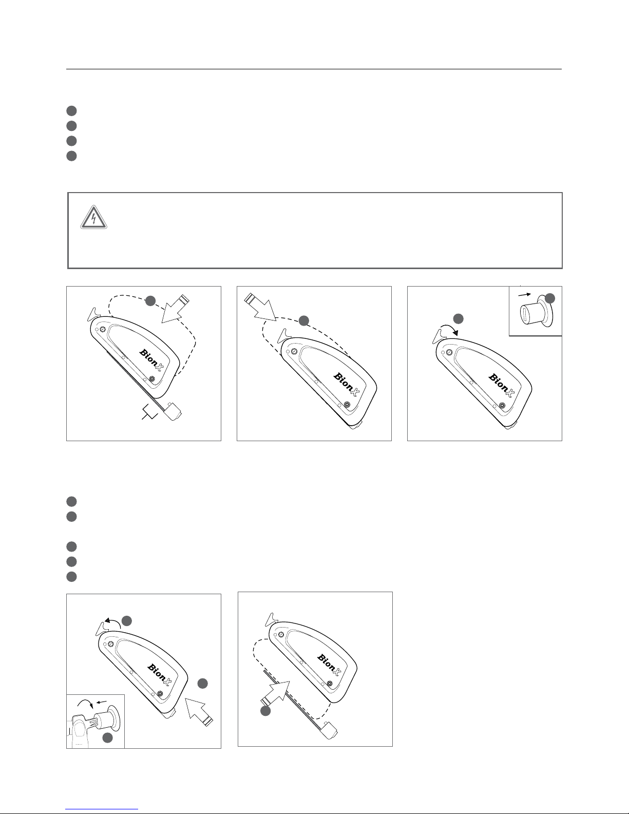
Inserting or Removing the Battery
Inserting the down tube battery
1Place the battery into the docking station
2Slide the battery down the rail gently towards the connector
3The release arm will close automatically as the battery slides towards the connector
4With the release arm almost closed, hold it in place and simultaneously press in the lock cylinder –
youwillheara“click”whenthelockcylinderisproperlyclosed
Removing the down tube battery
1TurnofftheBionXpropulsionsystem(noillustration)
2Lightly press on the battery release arm, insert the key and turn clockwise.
The lock cylinder will protract, freeing the battery release arm
3Remove the battery by opening the release arm
4Slide the battery upwards on the rail
5Lift the battery to remove
1” (25.4mm)
001
001
1” (25.4mm)
001
001
1” (25.4mm)
001
001
1
23
1” (25.4mm)
001
001
1” (25.4mm)
001
001
1” (25.4mm)
001
001
2
3
4
5
1” (25.4mm)
001
001
“click”
WARNING
Do not force the battery arm closed, or force the battery onto the battery dock. This can bend the
battery connector.
4
12
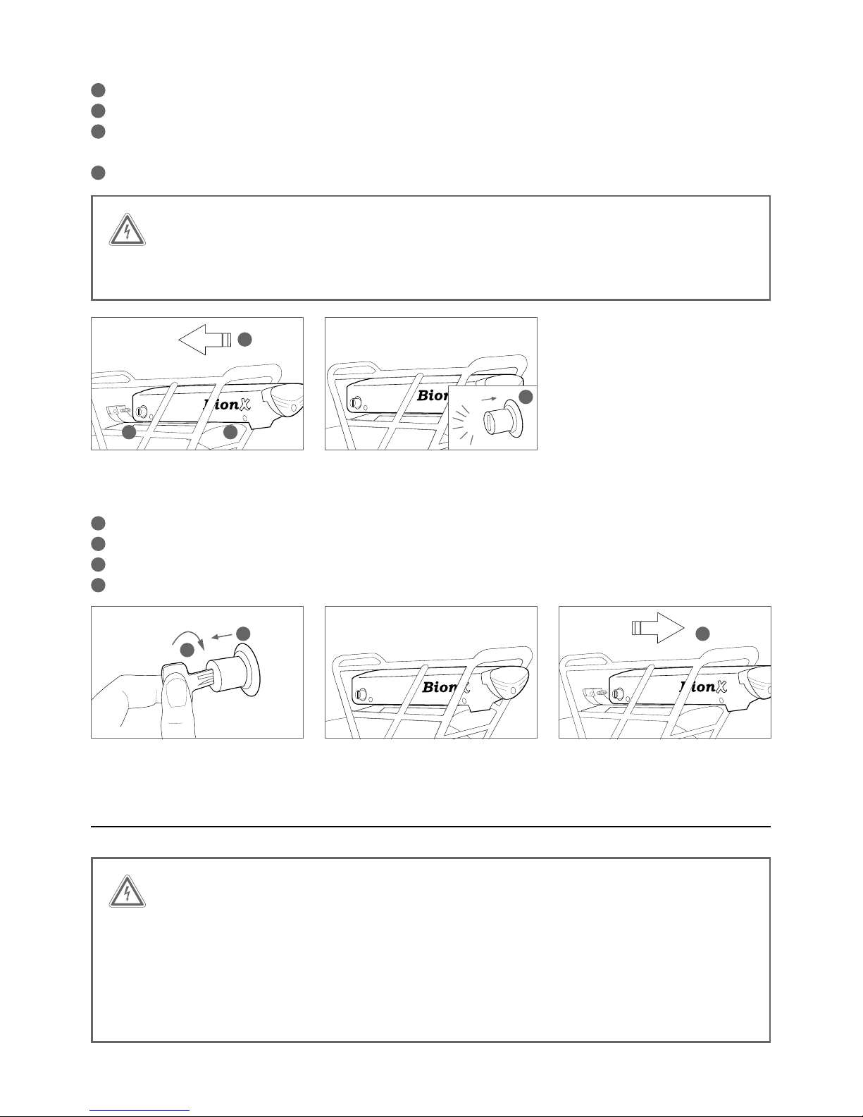
Inserting the rear rack battery:
1Openthelockcylinder:pleaseensurethatthekeyisremovedfromthelockcylinder
2Place the battery onto the battery harness
3Gently push the battery in a forward direction, towards the battery connector
Make sure the battery is inserted all the way, flush with the battery connector
4Push in the lock cylinder until a ‘click’ is heard
Removing of the rear rack battery:
1Turnoffthesystemviatheconsole(noillustration)
2Turn the key in the lock cylinder until it pops out
3Remove the key from the lock cylinder
4Pull the battery backwards, along the battery rail
Handling and Charging the Battery
WARNING
BionX batteries shall only be recharged with BionX chargers or BionX power supplies.
Never short circuit the battery by connecting the contacts of the battery. Never open the
battery. This could damage the battery and possibly lead to overheating or ignition of the
battery. The battery cannot be serviced by the user. Opening the battery case voids all
warranty and product liability claims. Never use a battery which has obvious damage
to the housing or the connector.
001
001
001
001
001
001
001
001
001
001
2
3 4
1” (25.4mm)
001
001
CLICK
WARNING
Do not force the battery onto the battery dock. This can bend the battery connector,
or damage the rear light.
1 2
3
4

13
Make sure that the battery is no longer connected to the power supply or charger once the charging
operation is complete. The Lithium Manganese battery cells have a low self-discharge rate, therefore a
continuous connection of the battery to the power supply or charger is not necessary. We recommend
that you fully charge the battery when it will not be used for a longer period of time, for example, before
storing it for the winter, and then recharge the battery at minimum every three months.
Itisbesttostorethebatteryinacoollocationattemperaturesbetween10°C(50°F)and25°C(77°F).
Neverstorethebatteryinlocationswherethetemperaturescanreachmorethan45°C(113°F)or
fallbelow-10°C(14°F).Thebatteryshouldneverbeexposedtoextremetemperatureuctuations
or humidity, and always protect the battery during storage from humidity to prevent corrosion on the
connectors. Never drop the battery, and protect it from physical damage. Damage may lead to short-
circuits, and as a result cause overheating or ignition of the battery.
Do not dispose of used batteries in regular household trash!
Be aware that used batteries must be disposed of properly!
BionX batteries can be returned to BionX to be recycled.
Charging the battery:
WARNING
Only use the BionX power supply or charger that was supplied with the system to charge
the battery. The use of other power supplies/chargers can damage the battery.
The BionX power supply/charger should be used exclusively for rechargeable batteries of
the specified type. The use of the BionX power supply/charger with batteries that are not
rechargable may damage those and could lead to overheating, or ignition of the battery.
Keep the power supply or charger away from water or moisture when charging and/or
connected to prevent electrical shock or short-circuits.
Do not use a power supply or charger that has obvious signs of damage to the cable,
housing, or the connector.
Extreme temperatures will affect battery life, especially during charging. Avoid charging in direct sunlight
or in very hot or cold temperatures. This will reduce the life of the battery considerably. We recommend
chargingthebatteryattemperaturesaround20°Cor65°F(roomtemperature).Thebatteryshouldbe
warmed to room temperature before it is charged, particularly when it was exposed to cold temperatures
during a ride.
The battery can be charged when mounted on the bicycle or removed from the battery docking station.
A Lithium Manganese battery does not have a memory effect, which means that the battery’s maximum
energy capacity is not affected if it is repeatedly recharged after only being partially discharged. The battery
does not need to be completely drained before charging. We recommend charging the battery after every
ride, preferrably when the battery state of charge display shows less than 50%. We recommend that you
fully charge the battery when it will not be used for a longer period of time, for example, before
storing it for the winter, and then recharge the battery at minimum every three months. When the
battery is depleted to the level where there is risk it could fall into deep discharge, the battery will signal that
a recharge is needed by beeping.

14
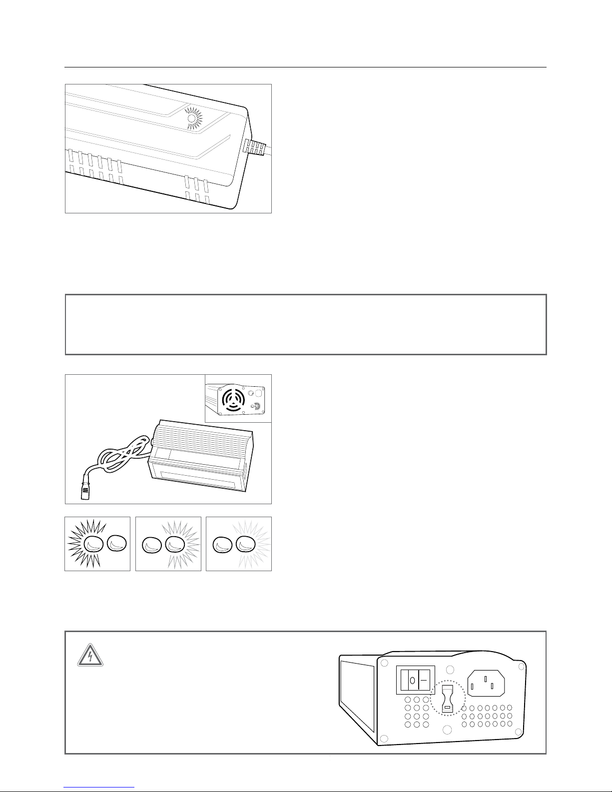
Power supply
SL system charging procedure (power supply)
• Connect power supply and battery by inserting the
charge connector into the touch port – the system
can be turned on or off
• Connect the plug of the power supply with the
power outlet
• Thebatterytouchport(LEDringaroundthecharging
connector) lights up red upon inserting and then
turns to amber during the charging process
• When fully charged, the colour of the LED ring
changes to green. The battery charging process is then complete
• Following this procedure the charging connector should be disconnected from the battery
• During the charging process you can check the battery state of charge through the console if the
batteryisconnectedtothesystem-a48Vsystemcanbeswitchedonwhileitischarging
This has my vote :)
Battery state Colour
100-85 % Green
85-25 % Amber
< 25 % Red
Checking the 48V Battery State of Charge
• Swipe your finger slowly over the touch port
• Battery state of charge LED will illuminate
• Allowten(10)secondsbeforecheckingstateofchargeagain
NOTE
The delivered power supply is suitable for the voltage ranges 110-115V or 220-230V.
There is no need to manually set the voltage range for international use.
The battery is fully charged after about 4 to 5 hours. Make sure that a completely charged battery is no
longer connected to the charger after the charging procedure is completed.
Touch port green = fully chargedTouch port amber = chargingTouch port red =
upon inserting
15
PL-250HT (EU) / PL-350HT (NA) systems charging
procedure, 2012 - present (single light charger)
• Connect the charger and battery by inserting the
charge connector into the charge port. The system
should be turned off
• Connect the plug of the charger with the power outlet
• The light on the charger will turn red automatically
• The same light will then turn yellow to indicate
charging, a fully depleted battery will take 4-5 hours
to charge
• The light will turn green, the battery is then fully
charged and the charging process is complete
• Following this procedure, the charger should be
disconnected
PL systems 22.2V, 26V, 37V charging procedure,
2011 and earlier (two LED charger)
• Connect the charger and battery by inserting the
charge connector into the charge port. The system
should be turned off
• Connect the plug of the charger with the power outlet
• The power switch must be set to ‘on’ and the red LED
will illuminate
• The LED to the right of the red LED will illuminate
yellow to indicate charging, a fully depleted battery
will take 4-5 hours to charge
• The right LED light will turn green, the battery is then
fully charged and the charging process is complete
• Following this procedure, the charger should be
disconnected
WARNING
Check input voltage when travelling with charger,
or using any outlet adaptor. Failure to adjust the
voltage switch on a two LED charger to the cor-
rect voltage range can result in damage to your
charger.
001
115
FUSE
This notch is very important
NOTE
The 37V single light charger is suitable for the voltage ranges 110-115V or 220-230V.
There is no need to manually set the voltage range, and there is no switch for this charger.
Left LED = red,
charger on
Right LED =
yellow, charging
Right LED =
green, fully charged
001
115
FUSE
This notch is very important
Chargers
001
115
FUSE
This notch is very important

16
Assist Mode / Generate Mode
The BionX propulsion system operates in four assist levels in the assistance mode, and in four charging
levels in the generate mode. In the assistance mode, your pedaling is assisted proportionally by an
electric motor that drives the rear wheel. A torque sensor is located on the axle of the electric motor and
measures the effort provided by the rider; this produces natural feeling assistance from the motor.
When in generate mode the electric motor functions as a generator and recharges the battery. When
going downhill, you can regulate your speed by varying the generate level. This generate function
provides a certain braking effect, however it does not replace legally required brakes. If the rear brake
lever is pulled, the drive system automatically enters generate mode. The range can therefore be extended
up to 15%, depending on the road conditions.
250HT (EU) / 350HT (NA) Motor performance
Assistance Level (A) Degree of Assist Riding Situation
135% Riding on level ground
275% Slight inclines, head wind
3150% Steep hills, strong head wind
4300% Verysteeproads
250/500 Motor performance
Assistance Level (A) Degree of Assist Riding Situation
125% Riding on level ground
250% Slight inclines, head wind
3100% Steep hills, strong head wind
4200% Verysteeproads
Generation Level (G)
1Slight downhill grade, tailwind
2Significant downhill grade, tailwind
3Steep descent
4Verysteepdescent

17
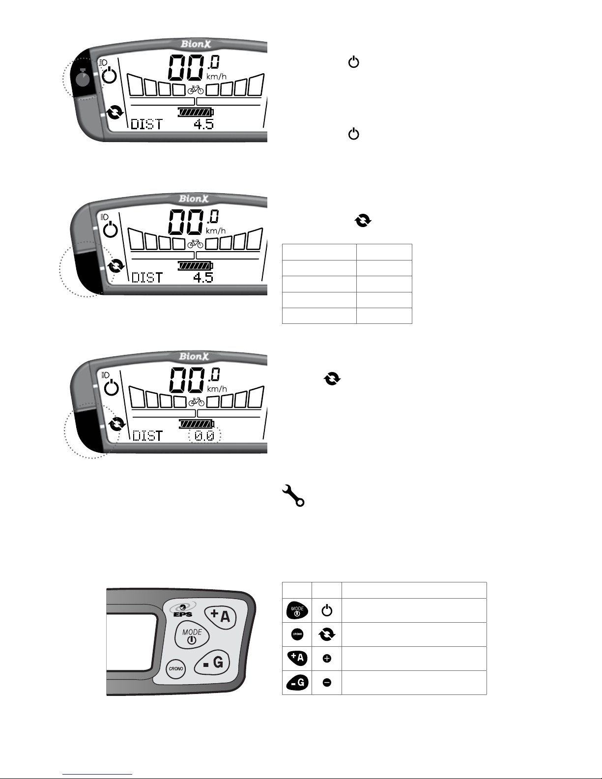
Operating the BionX Propulsion System
Turn the system on
Briefly push either top button on the console. The
battery will beep 4times and you will see a countdown,
this is the system perfoming a self check. After startup,
the system is always in mode(nomotorassist/
bike operation). To turn the system off, briefly push .
Thebatterywillbeep5times.After5minutesof“no
operation”thesystemturnsoffautomatically.
Select assistance/generate level
Push / keyformore/lessassist(seebar“elds1-4”
abovedisplay“A”).From mode push key to
enter continuous generate mode.
10
9
21
4 3
7
5
8
6
1. Power
2. Key
3. Key
4. Cycle
5. State of charge
indicator
6. (bicycle)mode
7. Speedometer
8. Tripdistance/averagespeed/
chronometer/odometer/clock
9. Assistlevel(A)
10.Generatelevel(G)
11. Wrench symbol
G2 Console
NOTE
The system performs a self check approximately every hour. Do not be alarmed if the
system turns itself on briefly, and off again, or if the touch port flashes momentarily.
11
18
Turn on backlight and bicycle light (if applicable)
Push and hold key for 4 seconds - display backlight
andbicyclelight(ifavailable,batteryintegrated)are
turned on.
Turn off backlight
Push and hold key again for 4 seconds.
Select the cycling computer functions
Briefly push the key to change between:
Trip Distance DIST
Odometer ODO
Clock CLOCK
Average Speed AVSPD
Chronometer CHRONO
To reset the cycle computer functions
Holdthe key for a few seconds to reset the distance,
chronometer, or average speed values to zero.
Please contact your BionX dealer for service.
For the G1 console, substitute mode for power, and
crono for cycle. The assistance toggle remains the same.
G1 G2
Mode/PowerbecomesPower
Crono becomes Cycle
Remains the same
Remains the same
If you require more information on the G1 console,
please contact your dealer.
4s
1
2
34
G1 Console

19
Operating the G2 throttle
Throttle engagement:
Default min. 3 kph to engage throttle
Note: throttle control is variable, and the force
gauge on the console reacts proportionally
Assistance levels 1-4:
From press for more assist
or for less assist
Generation 1-4:
From press for more resistance
or for less resistance
NOTE
The G2 throttle is only compatible with the G2 console, and may not be available in all
countries. Check with your local BionX dealer for local legislation and/or availability.

20
Programming the Basic Settings
In general, all basics settings for your BionX electric propulsion system are pre-set. Basic display functions
can be set by entering the programming mode. Contact your dealer to customize the advanced functions of
your system.
Turn on the programming mode
Simultaneously push and untilthedisplayshows“0000”.Therstzeroblinks.Changethevalue
of the selection with or and confirm with . Select the other digits in the same manner until the
desired program is displayed.
Note: For G1 programming, substitute (mode)and (crono)for (power)and (cycle)
respectively, plus and minus remain the same.
Code Description
2001 Selectkm/hormph
2002 Regeneration/brakeoutput(forreedswitch)0-40(ideally30-40)
2004 Clock adjust
2005 Tirecircumference(millimeters)
2009 FlipDisplayPlus/Minus0=powerleft,1=powerright(G2only)
Code 2001 Code 2002 Code 2004
Selectunit-km/hormph.Selectwith
or , and confirm with .
Default value: 30. Change with
and . Confirm with .
Selecthour/minuteswith ,
change value with and .
Confirm with .
Code 2005 Code 2009
Settiresize(inmm)-Selectdigits
one after another with or , and
confirm with .
Current setting of main functions is
displayed. Flip = 0, assist toggle is
on
the right side of console; Flip = 1,
assist
toggle is on the left side of console.
Confirm with .
WARNING
Do not use other programming codes without consulting your authorized dealer.
If you type the wrong code, please push the key to exit programming mode.
Table of contents
Other Bion X Bicycle Accessories manuals


Popular Bicycle Accessories manuals by other brands


Specialized
Specialized Elite CylcoComputer user manual

Sigma
Sigma BC 16.16 manual

Playcore
Playcore Dero Setbacks installation instructions

VDO Cyclecomputing
VDO Cyclecomputing x3dw instruction manual

Cateye
Cateye RAPID X2 manual

buratti meccanica
buratti meccanica Clorofilla Trail Use and maintenance manual


