Bioquell QUBE User manual

©Bioquell UK Ltd (2015). All rights reserved. USER MANUAL
TD069-O&M-001
REVISION 6
Bioquell UK Ltd
52 Royce Close
West Portway
Andover
Hampshire SP10 3TS
T:
F:
E:
W:
+44 (0)1264 835 835
+44 (0)1264 835 836
info@bioquell.com
www.bioquell.com
Page 1 of 80
Aseptic Processing Workstation
USER MANUAL

USER MANUAL
TD069-O&M-001
R.EVISION 5
Rev DescriDtaon Date C.R. o. Oris. chkd. ADDrd
1FIRST I55UE 3oh luly
2013 ]L PM ORC
2Screen navigation, glove & sl€€ve replac€ment added,
Eoad replac€able fu!€s added; Sectron 3.3.1 mov€d to
4.3.2; alarm condltionyactions added to tablei enors th Sept
2013 cR2455 JL PM ORC
3Ugdated al.rm table; ADMIN tunctrons, date & time,
time zone moved to superuisor acc6s; FiE 27 corrected;
updated screenshots; new pressure setpoints function
buttonj connector part nos. tor air Sampler add€d;
erroE corrected; seNice schedule updated,
23 )an
20L4 cR2560
cR2541 JL PM oRc
4additlon of us stenlant labelling notesj Environmental
Monitoring Level 4 opdon; 3,1 advice on positioning unit
added; Fig 20 updated; 3.1.2 advice on power covers
add€d; 3.3 bottle fill, storaqe and documents amended;
4,1.2 Rd 2 bottle holder (hange; 4.5 2 info moved to
product l€aflet 5.3.1 advice corre.ted; 5.3 infomation
amended; 8.2 am€ndedi 8.3 remoy€d, 9 volt free
12 May
2015 cR2689
cR2629 oRc ]H PGB
5Aeration cut-back added, p42, Maintenance penod
cla fied. Alams 40,41,72, 73 & 119 added. QRTP &
QBPM added. Addltionalinfo and trouble shooting on
.h<<-<.n.itivitw ^f H,O. <.nsor p7O
12 Aug 15 cR2889 ORC GK PGB
6Section 6.3 removed, 6.2 coveG all sePice information, 25 Sep 15 cR2971 @c- Ik stb
Bioquell designs, manufactures and supplies as a service a broad range of
bio-decontamination solutions for:
. rooms
. systems and processes
. laboratory equipment
. biomedical equipment
For further information and contact details refet to website
www.Bioquell.com
It is essential that the safety and operating instructions described in this manual
are observed.
These are the originat instructions
The Bioquell QUBE is only to be used by personnel who have been trained
by Bioquelt or their agents on its safe use. If the equipment is used in a
manner not specified by the manufacturer, the protection provided by the
equipment may be impaired.
These instructions assume the equipment has been installed in accordance with
the procedure detailed within TD069-IM-001'
oqu
Page 2 of 80
bt ell

USER MANUAL
TD069-O&M-001
REVISION 6
Page 3 of 80
Contents
1SAFETY ................................................................................................6
1.1 Safety Information relating to Hydrogen Peroxide and HPV Cycles.........6
1.1.1 Consumable H2O2bottle labelling symbols explained .....................8
1.2 General Safety Information relating to the QUBE ................................8
1.3 Warning Labels within the QUBE .......................................................9
2DESCRIPTION OF QUBE SYSTEM ........................................................... 10
2.1 Purpose of System ........................................................................ 10
2.2 QUBE Modules.............................................................................. 10
2.2.1 QUBE Hydrogen Peroxide Vapour Module - QHPV........................ 11
2.2.2 QUBE Extension Module - QEXT................................................ 11
2.2.3 QUBE Side Door Module – QSDM ..............................................11
2.2.4 QUBE Material Transfer Device - QMTD...................................... 12
2.2.5 QUBE Open Connection Module – QOCM .................................... 12
2.2.6 QUBE End Modules.................................................................. 12
2.3 Optional Sub-systems.................................................................... 14
2.3.1 Glove Tester........................................................................... 14
2.3.2 Sterility Test Pump.................................................................. 14
2.3.3 Integrated Environmental Monitoring......................................... 16
2.3.4 ‘Tri-Clover’ or Sanitary Connection Port to Chamber.................... 21
2.3.5 Ducted Extract........................................................................ 21
2.3.6 Additional Printer.................................................................... 21
2.4 Configurations.............................................................................. 21
2.5 Control Panel................................................................................ 21
2.6 Lighting ....................................................................................... 21
2.7 Modes of Operation ....................................................................... 22
2.7.1 Processing Mode..................................................................... 22
2.7.2 Bio-decontamination Mode....................................................... 22
3QUBE CONNECTIONS & SET-UP............................................................. 23
3.1 Position ....................................................................................... 23
3.2 Electrical Connections.................................................................... 23
3.2.1 External Electrical Connections ................................................. 23
3.2.2 Internal Electrical Connections.................................................. 25
3.3 Door Control................................................................................. 26
3.4 Hydrogen Peroxide Supply ............................................................. 27
4QUBE OPERATION................................................................................ 29
4.1 The Control Panel Explained ........................................................... 29

USER MANUAL
TD069-O&M-001
REVISION 6
Page 4 of 80
4.1.1 Icons..................................................................................... 29
4.2 Logging ON .................................................................................. 33
4.2.1 Loading the QHPV chamber...................................................... 34
4.2.2 Opening Doors........................................................................ 35
4.3 Bio-decontamination Mode............................................................. 35
4.3.1 Preparing to Start a Cycle........................................................ 35
4.3.2 Loading a Hydrogen Peroxide Bottle.......................................... 37
4.3.3 Running a Cycle...................................................................... 39
4.3.4 Cycle Phases .......................................................................... 39
4.3.5 Aborting a cycle...................................................................... 43
4.3.6 Printouts................................................................................ 44
4.4 Cycle Recipes ............................................................................... 44
4.4.1 Viewing Recipes...................................................................... 44
4.4.2 Pre-Loaded Recipes................................................................. 45
4.4.3 Creation and Editing Recipes .................................................... 45
4.5 Pressure Testing ........................................................................... 47
4.5.1 Chamber Leak Test ................................................................. 47
4.5.2 Glove Leak Testing (optional)................................................... 47
4.6 Operation of the Sterility Test Pump (optional) ................................. 47
4.7 Operation of Active Air Sampler...................................................... 47
4.8 Aseptic Hold................................................................................. 49
5SYSTEM ADMINISTRATION ................................................................... 50
5.1 System Information (only viewable)................................................ 50
5.2 OPERATOR editable functions ......................................................... 51
5.2.1 Set Language......................................................................... 51
5.2.2 Adjust Chamber light intensity.................................................. 51
5.3 SUPERVISOR editable functions ...................................................... 51
5.3.1 Suspending Processing Mode - system use not required............... 51
5.3.2 Door Interlocks....................................................................... 52
5.3.3 Set Time Zone........................................................................ 52
5.3.4 Date and Time........................................................................ 53
5.4 ADMINISTRATOR editable functions................................................. 53
5.4.1 Pressure Setpoints.................................................................. 53
5.4.2 Maximum Aseptic Hold Period................................................... 54
5.4.3 Manage Users......................................................................... 54
6PREVENTATIVE & SCHEDULED MAINTENANCE......................................... 57
6.1 Operator Maintenance ................................................................... 57

USER MANUAL
TD069-O&M-001
REVISION 6
Page 5 of 80
6.1.1 Cleaning ................................................................................ 57
6.1.2 Replacing Gloves .................................................................... 58
6.1.3 Fitting New Sleeves................................................................. 58
6.1.4 Changing the Printer Paper ...................................................... 59
6.2 Scheduled Maintenance ................................................................. 60
7TROUBLESHOOTING ............................................................................ 61
7.1 Alarms & Warnings........................................................................ 61
7.1.1 Alarm Screen ......................................................................... 61
7.2 Troubleshooting............................................................................ 69
8PARTS LIST......................................................................................... 70
8.1 Consumables................................................................................ 70
8.2 Replacement Parts ........................................................................ 70
9SPECIFICATION................................................................................... 71
10 EC DECLARATION OF CONFORMITY.................................................... 74
11 SCREEN NAVIGATION....................................................................... 75
12 GLOSSARY...................................................................................... 77
13 DEFAULT PASSWORDS ..................................................................... 78
United States of America only:
This equipment has been tested and found to comply with the limits for a Class B digital
device, pursuant to part 15 of the FCC Rules. These limits are designed to provide
reasonable protection against harmful interference in a residential installation. This
equipment generates, uses and can radiate radio frequency energy and, if not installed and
used in accordance with the instructions, may cause harmful interference to radio
communications. However, there is no guarantee that interference will not occur in a
particular installation. If this equipment does cause harmful interference to radio or
television reception, which can be determined by turning the equipment off and on, the user
is encouraged to try to correct the interference by one or more of the following measures:
—Reorient or relocate the receiving antenna.
—Increase the separation between the equipment and receiver.
—Connect the equipment into an outlet on a circuit different from that to which the receiver
is connected.
—Consult the dealer or an experienced radio/TV technician for help.

USER MANUAL
TD069-O&M-001
REVISION 6
Page 6 of 80
1SAFETY
1.1 Safety Information relating to Hydrogen Peroxide and
HPV Cycles
Safety instructions that must be observed when operating or servicing the
Bioquell QUBE or handling the Hydrogen Peroxide bottles are listed below.
Danger and Warning signs are used where there is a potential hazard to
personnel.
The mandatory symbol is used to describe other safety precautions that
should be followed before operating the equipment.
DANGER – CHEMICAL INJURY HAZARD
HANDLING HYDROGEN PEROXIDE
Wear personal protective equipment including
Eye protection, single use neoprene or vinyl gloves and protective
clothing.
HYDROGEN PEROXIDE LIQUID
can cause burns and blistering to the
skin and tissue damage to the eyes when in contact. HYDROGEN
PEROXIDE VAPOUR can cause irritation to eyes, nose, throat, lungs and
skin and breathing difficulties and coughing.
IN ALL CASES SEEK MEDICAL ADVICE.
ACTION TO BE TAKEN ON EXPOSURE TO HYDROGEN PEROXIDE
EYES Irrigate with sterile water for at least 10 minutes.
LUNGS Remove casualty immediately to fresh air, rest and keep warm.
SKIN Drench with water. If spilled on clothing remove immediately and wash
thoroughly.
MOUTH Rinse thoroughly with water and give plenty to drink. Do not induce
vomiting.
SAFETY OBSERVANCE IS ESSENTIAL WHEN USING THIS EQUIPMENT.
READ THIS SECTION CAREFULLY BEFORE USING THE EQUIPMENT

USER MANUAL
TD069-O&M-001
REVISION 6
Page 7 of 80
SPILLAGES
Mop up with plenty of water and run to waste, diluting at least 20:1.
Always ensure wipes used to mop up spillages are rinsed with cold water
before being put in waste bins; there is a risk of spontaneous combustion
if thrown directly in waste bin containing other materials.
HANDLING HYDROGEN PEROXIDE BOTTLE
Wear protective gloves. Inspect outer bag containing peroxide bottle for
signs of liquid before opening. If any liquid is present in the bag DO NOT
OPEN. Discard safely.
If no signs of liquid in the bag open carefully and remove bottle. Keep
bottle upright at all times.
Handle bottle in accordance with safety data supplied on bottle label and
packaging.
BEFORE RUNNING A CYCLE
Check that all doors and front access windows are closed and seals
inflated.
DURING A CYCLE
·Do not attempt to open the QUBE before the end of the cycle or to
open a QUBE door unless the door switch is illuminated GREEN.
·Observe warnings and alarms displayed on the control panel.
·Do not attempt to disengage or remove the Hydrogen Peroxide liquid
bottle.
AT THE END OF AERATION
Check that the vapour concentration is at, or below, the country’s
Occupational Exposure Limit (OEL) (Long-term exposure limit is 1ppm
and short-term is 2ppm in the UK). In USA: the Permitted Exposure Limit
(PEL) has a Threshold Limit Value (TLV) of 1ppm for eight hours exposure
a day.
IF THE CYCLE ABORTS DURING
GASSING OR AERATION
Check that the vapour concentration is at, or below, the OEL before
opening the QUBE.
If above the OEL run an “AERATION ONLY” cycle in accordance with the
operating instructions until the safe concentration level is reached.
VISIB
LE LIQUIDS
in the enclosure must be treated as concentrated
Hydrogen Peroxide. Observe Hydrogen Peroxide handling precautions
and remove liquid by diluting with water at least 20:1 and wiping up.
EXTERNAL DISCHARGE
of vapours by ventilation from the enclosure to
atmosphere during the aeration period must avoid leakage of Hydrogen
Peroxide vapours within the building.

USER MANUAL
TD069-O&M-001
REVISION 6
Page 8 of 80
1.1.1Consumable H2O2bottle labelling symbols explained
CHEMICAL INJURY
HAZARD Hydrogen Peroxide
liquid is hazardous –
corrosive
CHEMICAL INJURY
HAZARD Hydrogen Peroxide
liquid is harmful and
is an oxidizing agent
RFID This product contains an
RFID tag
Note: Further information relating to safety for the Hydrogen Peroxide is
available from on the MSDS provided with the consumable.
1.2 General Safety Information relating to the QUBE
WARNING – EQUIPMENT DAMAGE
The
QUBE system
, once installed, only require
s
moving forward to enable
cleaning of all sides. If the equipment is to be moved across a threshold or
any substantial distance then it should be completely disassembled and re-
assembled by trained personnel to ensure safe operation once re-
positioned. Cables must not, at any time, be trailed causing a trip hazard.
Ensure supporting feet (x2) are retracted prior to moving any QUBE
system. The weight of the QUBE system is dependent upon the
configuration; however, local manual handling regulations must be adhered
to. To prevent damage to the QUBE do not manoeuvre by handling the front
screen, glove ports or gas strut covers.
Avoid moving the
QUBE system
(or any part thereof)
once a cycle has been
started.
Prior to switching on the QUBE system ensure
all doors are closed.
Operate the equipment strictly in accordance with the Operating
Instructions.

USER MANUAL
TD069-O&M-001
REVISION 6
Page 9 of 80
Major r
epairs or adjustments to the Bioquell
QUBE
should only be made by
a Bioquell Service Provider or those trained to perform such procedures by
Bioquell. Non-routine maintenance performed by unqualified personnel or
installation of unauthorised parts could cause personal injury or result in
damage.
The equipment must be serviced in accordance with the Maintenance
Schedule to maintain safe performance. Potential hazards or failure of
performance may occur if the equipment is not serviced by trained and
authorised personnel. Contact your Bioquell Service Provider to schedule
preventative maintenance or for emergency repairs.
Use of traditional alcohol
sprays and
wipes must be avoided to prevent
damage to the sensitive electrical components within the QUBE system
especially the Hydrogen Peroxide sensor.
Use of paper or other abrasive cloths could potentially damage the QUBE
front screen during cleaning.
Do not cover the top of the QMTD as this could potentially block the filter.
DANGER – PERSONAL INJURY HAZARD
The Bioquell
QHPV
m
odule
weigh
s
approx
.
280
kg
(
617
lbs)
; the QEXT
module approx. 240Kg (529.1 lbs) and the QMTD module approx. 64 kg
(141 lbs). Local manual handling regulations and SOPs must be adhered to
when moving this equipment to prevent personal injury. Assisted
mechanical devices will be required if moving over a threshold or for any
distance.
Take care when moving the Bioquell
QUBE
on inclined surfaces.
Park the Bioquell
QUBE
on flat surfaces only. Secure by
extending the
support feet to stop the unit moving.
Do not tilt the unit over as toppling may occur.
The Bioquell
QUBE
contains electrical connections. Always disconnect the
power supply before gaining access to electrical and pneumatic systems for
inspection or maintenance. Access to these systems should be restricted to
trained personnel; failure to do so may cause an ELECTRICAL INJURY
HAZARD.
1.3 Warning Labels within the QUBE
ELECTRICAL INJURY
HAZARD Only trained personnel
should be accessing the
electrical system

USER MANUAL
TD069-O&M-001
REVISION 6
Page 10 of 80
2DESCRIPTION OF QUBE SYSTEM
2.1 Purpose of System
The Bioquell QUBE is an aseptic processing workstation with integrated HPV
decontamination system. This system can be used for various applications
including: sterility testing; pharmacy compounding, aseptic material transfer and
others that require an aseptic environment. It is a modular system that is
configurable to the Client’s needs.
The QUBE is loaded via the front access window. Dependent upon the application,
the QUBE may be supplied with Bioquell “SafeSort1”, internal racking and rails.
There is a Product Description Sheet for each of the optional accessories available
from Bioquell.
All replacement or serviceable parts are accessible from the front of the QUBE;
thereby allowing it to be positioned against a wall. Key access is required to
components that may present a hazard.
2.2 QUBE Modules
The QUBE system is modular incorporating a QUBE Hydrogen Peroxide Vapour
(QHPV) Module and additional modules dependent upon ordered configuration:
•QUBE Extension Module (QEXT) (max.2)
•QUBE Side Door Module (QSDM)
•QUBE Material Transfer Device (QMTD)
·QUBE Open Connection Module (QOCM)
·QUBE Closed Connection Module (QCCM)
·QUBE Rapid Transfer Port (QRTP)
·QUBE Blank Plate Module (QBPM)
As standard the QHPV Module is supplied without integrated continuous particle
monitoring or active air sampling systems (unless ordered as part of the
configuration). However, it is fitted with the connections for these systems
including having a “Dummy cone” in place.
Figure 1 depicts one typical configuration of a QUBE system. The QUBE is
available as a 1-chamber, 2-chamber or 3-chamber system of various
configurations.
1Bioquell SafeSort is a prescription decontamination system designed for gassing components and
used in hospital pharmacy applications.

USER MANUAL
TD069-O&M-001
REVISION 6
Page 11 of 80
QHPV
module
Figure 1: Typical Configuration of QUBE System
QEXT
module
QMTD
module
2.2.1QUBE Hydrogen Peroxide Vapour Module - QHPV
This chamber incorporates the HPV decontamination system and controls
including the touch screen. Each QUBE system incorporates a QHPV module. The
complete system is controlled via a Control Panel from the QHPV Module. Figure 2
depicts the main features of this module.
2.2.2QUBE Extension Module - QEXT
This module can be positioned either left, right or both sides of the QHPV
chamber. It enables the Operator to continue to ‘work’ on one load whilst
simultaneously decontaminating another load. If the system is configured with
more than one QEXT module then one may be used as an accumulator to store a
load whilst one is being processed and one being gassed.
2.2.3QUBE Side Door Module – QSDM
This module is positioned either on the left hand end, or right hand end, or both
ends of the chambers. It can be used to transfer the load between QUBE
modules, while providing a physical separation between modules allowing the
QHPV unit to run cycles on its own.

USER MANUAL
TD069-O&M-001
REVISION 6
Page 12 of 80
2.2.4QUBE Material Transfer Device - QMTD
This module is positioned either on the left hand end, right hand end, or both
ends of the chambers. It can be used to transfer the load into and/or out of the
QUBE system.
2.2.5QUBE Open Connection Module – QOCM
The QOCM allows for a large open aperture between QEXT modules only, thus
making them into a 4-glove device.
2.2.6QUBE End Modules
The end panels for the QUBE system where a QMTD is not fitted can be one of the
following:
QUBE Closed Connection Module – QCCM
This is a solid end panel
QUBE Rapid Transfer Port – QRTP
This end panel has a 190mm diameter RTP fitted to it. There is a left and a right
hand version ensuring that the RTP always hinges to the back.
QUBE Blank Plate Module – QBPM
The end panel has a circular blank 3mm thick stainless steel sheet, through which
penetrations can be made to suit application.

USER MANUAL
TD069-O&M-001
REVISION 6
Page 13 of 80
Control Panel
Chamber test
point*
Processing
chamber
Stirrer
fans (2x)
Clear front
access window
H2O2Bottle
module
Key access to
components of
pneumatic
system
Figure 2: QHPV Module
Vaporiser outlet
Internal electrical
connections
Environmental
Monitoring
Module
Glove ports
(gloves and
sleeves not
shown)
Printer
Key access to
electrical system
Foot switch for
opening QSDMs
* Mating part is Bioquell part number H03020720 and has a 5/16” (8mm) Hose
barb outlet.
USER MANUAL
TD069-O&M-001
REVISION 6
Page 14 of 80
2.3 Optional Sub-systems
The following sub-systems are not integrated into the QUBE as standard but
available to order as part of the configuration:
2.3.1Glove Tester
Figure 3: Glove Tester
The Glove Tester (Part No.TD069-5900)
is an accessory that can be supplied
with the QUBE system to enable the
leak testing of sleeves and gloves.
A glove test cannot be performed on a
QUBE module which is being
decontaminated.
For information on how to use the glove tester refer to Instructional Leaflet
TD069-5900_PDS (supplied with glove tester).
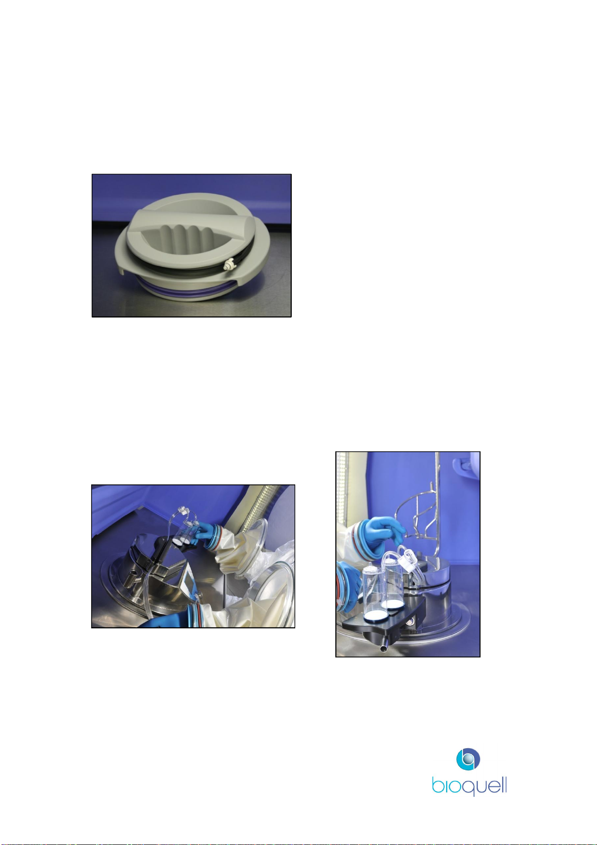
2.3.2Sterility Test Pump
The QUBE system has been designed to work with the Merck Millipore SteriTest
Symbio Flex or Equinox Isofit Pump for sterility testing applications. The
“SteriTest” unit is fully integrated into the chamber moulding.
Figure 4: Sterility test unit in use (Equinox shown)

USER MANUAL
TD069-O&M-001
REVISION 6
Page 15 of 80
Sterility Test
Pump (Merck
Millipore
Equinox or
Symbio Flex)
Housing for
SteriTest pump
controller/power
supply and
continuous
particle
monitoring
system. Access
required by
Service
personnel.
Figure 5: SteriTest unit installed
Drain,
passes
through floor
to allow safe
disposal
outside the
unit (see
Fig.6)
Footswitch
operation of
the SteriTest
pump.
Prior to use of SteriTest unit ensure tubing is connected to drain. Connect tubing
as shown in Figure 6.
Figure 6: Push-in connection

USER MANUAL
TD069-O&M-001
REVISION 6
Page 16 of 80
For details on how to use the “SteriTest” pump refer to the Manufacturer’s
Instructions (supplied if part of ordered configuration).
To remove the drain connection press release button and pull out, as shown in
Figure 7.
Figure 7: Removal of drain tubing
It is advisable to execute the scheduled maintenance of the “SteriTest” unit whilst
the QUBE is being serviced. Contact Merck Millipore for scheduling the Servicing
of this unit (refer to Section 6.2 for contact details).
The QUBE may also be supplied with the “SteriTest” pump drain only if a client-
supplied free standing SteriTest pump is installed.
Racking has been designed by Bioquell for this application. This racking is
available in kit form; refer to TD069-6200_PDS for how to assemble.
2.3.3Integrated Environmental Monitoring
2.3.3.1 Level 1 Environmental Monitoring Package
As standard the QUBE QHPV and QEXT chambers have been designed to allow
for Level 1 Environmental Monitoring to be performed. Level 1 Environmental
Monitoring consists of:
·Periodic particle monitoring checks using a portable particle counter
connected to the pre-fitted tube and supplied ISO-Kinetic cone. A blanking
cone is also supplied, to be fitted instead of the ISO-Kinetic cone when
sampling is not taking place. The particle monitor is not supplied by
Bioquell.
·An integral connector inside the chamber can be used to connect to an
Active Air Sampler (see Fig. 21, Item 2), and a coupler is provided (see
Fig. 12) on the QUBE’s right leg to enable connection to the air sampler’s
power device. The Active Air Sampler and power device and settle plates
are not supplied by Bioquell.
·Settle plates and other alternative monitoring methods may be adequate,
as shown in Figure 8.

USER MANUAL
TD069-O&M-001
REVISION 6
Page 17 of 80
Figure 8: Level 1 Environmental
Monitoring System Diagram
Figure 9: Level 1 Environmental
Monitoring System Diagram
ISO-Kinetic cone, blanking cone and integral cable and connectors for Active Air
Sampler are supplied with units. The connectors are specifically for the SAS
Isolator 180 Sampler. If not using a Bioquell-supplied Sampler then a LEMO
connector (LEMO Part No. FGL.2K.302.CLLC55Z) must be fitted to the Sampler.
Cable between sampler and chamber marked with * can be supplied separately
(Bioquell Part No. TD069-0621)
ISO-Kinetic cone
Figure 10: ISO-Kinetic Cone Figure 11: Blanking Cone
Settle plate
Particle
counter
ISO
-
cone
Active Air
Sampler
Air sampler’s
power device
Integral cabling
and connectors
for Active Air
Sampler and its
power device
*

USER MANUAL
TD069-O&M-001
REVISION 6
Page 18 of 80
Connecting the Active Air Sampler
Figure 12: Connecting Active Air
Sampler
Active Air Sampler, location shown, is
plugged into the dedicated connector
within the chamber (refer to Fig. 21,
Item 2)
Keyed bulkhead coupler supplied on
QUBE right leg for attaching the
sampler’s power device.
2.3.3.2 Level 2 Environmental Monitoring Package
The QUBE QHPV and/or QEXT chambers are optionally supplied with an Active
Air Sampler (See Figure 13) to enable Level 2 Environmental Monitoring; the air
sampler is powered and controlled through the QUBE’s touch screen.
Figure 13: Active Air Sampler
The Active Air Sampler has a stainless
steel head. It is permanently placed
within the QUBE and attached through
a dedicated DC supply connector;
labelled thus:

USER MANUAL
TD069-O&M-001
REVISION 6
Page 19 of 80
Figure 14: Level 2 Environmental Monitoring System Diagram
As Level 1, when particle monitoring is to be performed the blanking ISO-Kinetic
cone fitted to the QUBE should be replaced with the supplied ISO-Kinetic cone.
2.3.3.3 Level 3 Environmental Monitoring Package
The QUBE is optionally supplied with an Active Air Sampler and a proprietary
integrated continuous particle monitoring system with integrated vacuum pump.
An ISO-kinetic cone is fitted to the QUBE chamber.
Figure 15: Level 3 Environmental Monitoring System
CONTROLLER

USER MANUAL
TD069-O&M-001
REVISION 6
Page 20 of 80
Sample air is fed continuously to the particle counter monitoring unit via tubing
from the ISO-Kinetic cone. See Figure 15.
Pharmagraph enVigil-PnP logging software is supplied to output and record
results to a PC; the PC is not supplied by Bioquell. Up to 2 chambers can be run
from one software license. Refer to manufacturer’s instructions for use.
2.3.3.4 Level 4 Environmental Monitoring Package
The QUBE is optionally supplied with a proprietary integrated continuous particle
monitoring system with integrated vacuum pump. An ISO-kinetic cone is fitted to
the QUBE chamber. Pharmagraph enVigil-PnP logging software is supplied and
record results to a PC. The PC is not supplied by Bioquell.
An integral connector inside the chamber can be used to connect to an Active Air
Sampler (see Fig. 20, Item 2), and a coupler is provided (see Fig. 12) on the
QUBE’s right leg to enable connection to the air sampler’s power device. The
Active Air Sampler and power device and settle plates are not supplied by
Bioquell.
Figure 16: Level 4 Environmental Monitoring System
Table of contents


