Biorock ECOROCK-700 Operation manual

PAGE 1 / 47 Installation and User guide –ECOROCK 700 to 900 Units –05-12-2016
INSTALLATION & USER GUIDE
BIOROCK TREATMENT UNITS:
ECOROCK-700
ECOROCK-800
ECOROCK-900

PAGE 2 / 47 Installation and User guide –ECOROCK 700 to 900 Units –05-12-2016
TABLE OF CONTENTS
A. INSTALLATION GUIDE .............................5
B. USER GUIDE...........................................27
C. APPENDICES ..........................................39

PAGE 3 / 47 Installation and User guide –ECOROCK 700 to 900 Units –05-12-2016
Dear Customer,
Congratulations on your purchase of this BIOROCK Domestic Sewage Treatment Plant. Your new
BIOROCK will guarantee years of trouble-free operation, peace of mind and protection for the
environment.
We highly recommend that you familiarize yourself with this guide for the installation,
commissioning and maintenance of your new BIOROCK system.
The instructions for the maintenance and visual checks of the system will ensure that you have a
reliable and long-lasting sewage treatment plant.
Please do not hesitate to contact your BIOROCK distributor for any queries or further assistance.
Thank you for choosing BIOROCK.
The installation and commissioning of your BIOROCK® system should be carried out by a BIOROCK
trained and approved installer. Your installer will be able to offer you a maintenance contract. The
BIOROCK Warranty is only valid if the required maintenance is carried out by a BIOROCK trained and
approved installer.
Should you not wish to take out a maintenance contract, make sure you have your sewage treatment
plant inspected and maintained on a regular basis by an industry trained, competent wastewater
professional.
BIOROCK S.à.r.l.
4-5 ZAE le Triangle Vert
L-5691 Ellange Luxemburg
E-mail: [email protected]
Telephone: +352-26-17 66 33
Distributor’s name:
Contact person:
Address:
E-mail:
Telephone:
READ CAREFULLY

A. INSTALLATION GUIDE
PAGE 4 / 47 Installation and User guide –ECOROCK 700 to 900 Units –05-12-2016
A. INSTALLATION GUIDE
ECOROCK-700 to -900 UNITS

A. INSTALLATION GUIDE –TABLE OF CONTENTS
PAGE 5 / 47 Installation and User guide –ECOROCK 700 to 900 Units –05-12-2016
TABLE OF CONTENTS
1. THE ECOROCK SEWAGE TREATMENT PLANT.................................................................. 6
1.1. General points .........................................................................................................................6
1.2. Sizing ........................................................................................................................................6
1.3. Precautions ..............................................................................................................................6
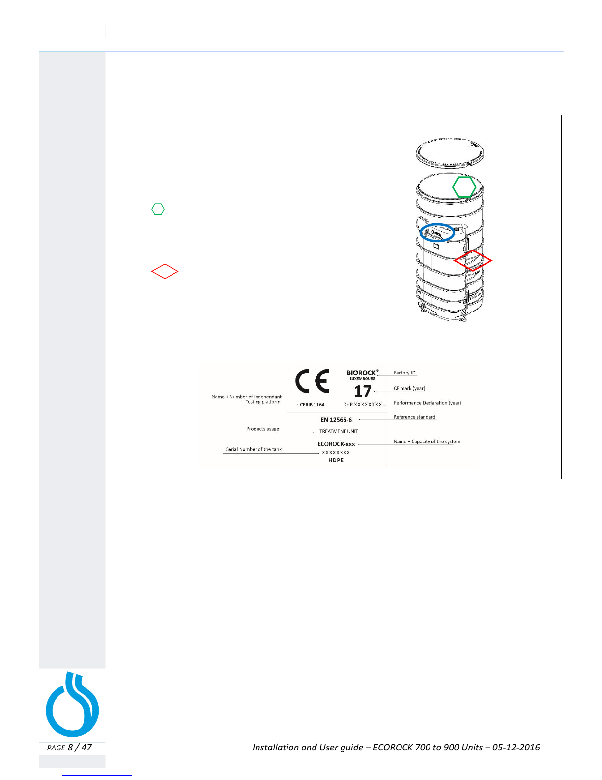
1.4. Identification ............................................................................................................................8
1.5. Handling and transport ............................................................................................................8
2. OPERATING PRINCIPLES OF THE ECOROCK SEWAGE TREATMENT PLANT ....................... 9
2.1. Primary Tank –Operating principle..........................................................................................9
2.2. ECOROCK Treatment Unit –Operating principle....................................................................11
2.3. ECOROCK Treatment Unit –Technical....................................................................................11
3. INSTALLATION LAYOUTS ............................................................................................. 12
3.1 Installation layout n°1.: Gravity discharge (non-electric)......................................................12
3.2 Installation layout n°2.: Pumped discharge (pump after PT) ................................................12
3.3 Installation layout n°3.: Pumped discharge (pump after ECOROCK unit) .............................12
4. INSTALLATION OF THE TANKS .................................................................................... 13
4.1 Principles and constraints of installation works.....................................................................14
4.1.1 Before installation of the complete system.............................................................14
4.1.2 Installation of the Primary Tank .............................................................................14
4.1.3 Installation of the ECOROCK treatment unit ..........................................................15
4.2 Installation in dry ground conditions .....................................................................................15
4.2.1 Installation and digging in dry ground conditions...................................................15
4.2.2 Installation of the Tanks in dry ground conditions..................................................15
4.2.3 Backfilling in dry ground conditions ........................................................................16
4.3 Installation in wet ground conditions.....................................................................................16
4.4 Installation in specific sites.....................................................................................................18
4.4.1 Installation in difficult areas and sites ....................................................................18
4.4.2 Installation in difficult ground conditions ...............................................................18
4.4.3 Backfilling in difficult sites.......................................................................................18
4.5 Installations under roads, courtyards or storage areas..........................................................19
4.6 Other specific cases ................................................................................................................19
4.6.1 Incline too steep ......................................................................................................19
5. VENTILATION AND WATER DISTRIBUTION .................................................................. 20
5.1 Ventilation of the Primary Tank..............................................................................................20
5.2 Ventilation of the BIOROCK® treatment unit .........................................................................21
5.3 Water distribution ..................................................................................................................21
5.4 BIOROCK® media ....................................................................................................................22
5.5 Securing the lids......................................................................................................................23
6. STOPPING AND RESTARTING THE SYSTEM .................................................................. 24
7. CONFORMITY AND WORK COMPLETION .................................................................... 24
8. RECOMMENDATIONS OF USE AND MAINTENANCE .................................................... 24
9. COMPLIANCE WITH REGULATIONS AND STANDARDS .................................................. 24
10. WARRANTY .............................................................................................................. 25

A. INSTALLATION GUIDE 1. THE ECOROCK TREATMENT PLANTS
PAGE 6 / 47 Installation and User guide –ECOROCK 700 to 900 Units –05-12-2016
1. THE ECOROCK SEWAGE TREATMENT PLANT
1.1 GENERAL POINTS
The ECOROCK SYSTEMS from BIOROCK are compact non-electric Sewage Treatment Plants. The
treatment relies on the revolutionary BIOROCK biological purification process. The ECOROCK sewage
treatment unit is exclusively designed for domestic waste water purification.
The BIOROCK plant consists of a Primary Tank and the ECOROCK Bioreactor. Both parts (Primary Tank
and Bioreactor) must be ventilated.
A small pump can be installed in an integrated pump shaft to lift the treated water and discharge to a
higher level if needed.
BIOROCK recommends the installation of an effluent sampling point at the outlet of the treatment
unit.
The ECOROCK treatment unit can be installed (retrofitted) after a non-BIOROCK Primary Tank,
provided that this tank is properly sized, equipped with an efficient effluent filter and properly
vented.
1.2 SIZING
The ECOROCK-700 to -900 units have a capacity of 4*, 5*, 6* and 8* P.E. (Person Equivalent).
The capacity of the individual ECOROCK unit can be increased if the required final effluent quality is
of a lower standard than the results, achieved during the EN-12566-3 Performance test.
* Based 150 l.p.e.day
UNITS PARAMETERS
ECOROCK -
700
ECOROCK -
800
ECOROCK-900
MAX.PEOPLE
EQUIVALENT
4 P.E
5 P.E.
6 P.E.
RECOMMENDED VOLUME
PRIMARY TANK
2000 L
3000 L
3000 L
WASTE WATER TREATED
150 L/day/ PE
150 L/day/ PE
150 L/day/ PE
TREATED ORGANIC LOAD
(BOD5)
0,24 Kg/day
0,30 Kg/day
0,36 Kg/day
1.3 PRECAUTIONS
Please note that BIOROCK shall not be responsible for any installation design parameters and
groundworks at any case. We recommend to involve a civil engineer or a specialized design office
in the design of the system installation if necessary and to follow best practices of the industry.
Important precautions for the proper use of the BIOROCK system: Only domestic sewage should
enter the system; no rainwater is allowed.
To ensure the good working order of the BIOROCK system, the use of automatic toilet cleaners,
electric waste-disposal systems and pumps equipped with blades are not to be used.
If there is a professional kitchen on site, an efficient and properly sized grease trap should be
installed. The grease trap should be installed before the primary tank.

A. INSTALLATION GUIDE 1. THE ECOROCK TREATMENT PLANTS
PAGE 7 / 47 Installation and User guide –ECOROCK 700 to 900 Units –05-12-2016
Do not dispose of the following items to the BIOROCK system:
Kitchen or motor oils, fats, wax, resin, paint, solvents, hydrocarbon-based products (petrol, crude oil
etc.), any pesticide or antibacterial product, items of a toxic nature, boiler or air-conditioning
condensate, swimming pool backwash, rainwater, drainage water or ground-water.
An effective effluent filter should be installed in the outlet of the Primary Tank, before the water
goes on to the Bioreactor.
We recommend that pipework after the ECOROCK unit should allow sampling.
Special care should be taken with the aeration of the system. The aeration should be checked by the
installer using a smoke test once pipework and ventilation ducts have been connected and before
backfilling the system. The smoke test should be performed under normal representative conditions.
Each system should be vented independently and equipped with its own ventilator (wind driven or
electrical). The number of elbows used in the pipework should be limited as much as possible. 90o
elbows should not be used, 45oelbows should be used instead. The high air outlets should be
installed as close as possible to the low air inlets.
Achieving efficient ventilation is the responsibility of the installer as he is familiar with the
implementation, site and local conditions that may interfere in the system’s venting.
The Primary Tank should be aerated separately in accordance with the manufacturer's instructions.

A. INSTALLATION GUIDE 1. THE ECOROCK TREATMENT PLANTS
PAGE 8 / 47 Installation and User guide –ECOROCK 700 to 900 Units –05-12-2016
1.4 IDENTIFICATION
Before installing please copy the serial number of each tank on to the documents to be kept by the
customer (Appendix 5 of this Guide.)
1.5 HANDLING AND TRANSPORT OF THE TANKS
Lifting eyes are situated on the top of each tank, enabling lifting by crane or JCB. The tanks should be
handled, transported and stored with care after delivery to avoid being damaged.
When looking at the tank facing the BIOROCK logo, the serial number is:
-On an identification tag inside the tank, and
/or
Marked as on the drawing below
-Engraved on the area to your right at the
bottom of the rounded top.
Marked as on the drawing below
M Detail of the identification plate inside the tank:

A. INSTALLATION GUIDE 2. OPERATING PRINCIPLE OF ECOROCK 700->900 UNITS
PAGE 9 / 47 Installation and User guide –ECOROCK 700 to 900 Units –05-12-2016
2. Operating principle of an ECOROCK Sewage Treatment Plant
A BIOROCK system is composed of a Primary tank and an ECOROCK treatment unit. Initially the raw
sewage enters the primary tank to provide separation and the breakdown of organic solids (Primary
Treatment). The sewage then passes through an effluent filter before discharging into the ECOROCK
Treatment Unit which incorporates the well proven aerobic digestion process (Secondary Treatment)
and filtration process (Tertiary Treatment).
2.1 THE PRIMARY TANK
The effluent (domestic wastewater composed of black water: origin toilets –and grey water: origin
kitchen, bathroom, laundry) enters the primary tank. This Primary Tank carries out the first basic
phase of wastewater treatment, that is separation of solids and fats by flotation (formation of a
grease layer) and by clarification (the suspended solids sink to the bottom of the tank by natural
settlement). Separated solids building up at the bottom of the primary compartment are called
“primary sludge”. This sludge breaks down in time by anaerobic digestion.
The primary tank should always be equipped with an efficient effluent filter. This filter holds back
remaining suspended solids, fats and other floating matter which enables a higher quality of pre-
treatment.
2.1.1 Ventilation of the Primary Tank
Any Primary tank should have a proper unencumbered low level and high level vent. The low level
vent should be connected directly on the outlet side of the tank and the high level on the inlet side
and should not be positioned more than 10 m1from the tank and at a minimum height of 4 m1with
a wind driven ventilator also fitted. The water inlet should be made air tight. All ventilation should
be checked with a smoke test.
2.1.2 Performance of the Primary Tanks (PT)
If the Primary Tank being used is not a BIOROCK tank, make sure that the quality of the effluent
from the PT meets the BIOROCK requirements. Proper ventilation of a PT is necessary, not only to
avoid smell problems, but also to evacuate the gasses produced. A Primary Tank generates
malodorous gases like hydrogen sulphide (H2S). Ventilation of the gasses is necessary to prevent
H2S being transformed into harmful sulphuric acid (H2SO4). Sulphuric acid will harm the biological
process and can cause degradation of the BIOROCK Media.
BIOROCK requires the following performance of a PT in front of the ECOROCK unit:
Composition of normal domestic wastewater (according to EN12566-3+A2 Annex B.3.2):
Variation
BOD5*1: 150 - 500 mg O2/l
COD*1: 300 –1000 mg/l
S.S.: 200 - 700 mg/l
KN: 25 - 100 mg/l
NH4-N: 22 - 80 mg/l
P-Total: 5 - 20 mg/l
*1: The ration between BOD5and COD should always be < 2

A. INSTALLATION GUIDE 2. OPERATING PRINCIPLE OF ECOROCK 700->900 UNITS
PAGE 10 / 47 Installation and User guide –ECOROCK 700 to 900 Units –05-12-2016
Minimum performance requirements of a Primary Tank*2:
Effluent PT Average
EN 12566-6: 2008
BOD5: 100 - 350 mg O2/l 200 ± 50 mg O2/l
COD: 200 - 600 mg/l
S.S.: 40 - 150 mg/l 80 ± 20 mg/l
KN: 35 - 100 mg/l
NH4-N: 30 - 80 mg/l
P-Total: 4 - 20 mg/l
*2: The sampling should be done with a minimum 24 hour sampling
The effluent is easy biodegradable if the ratio of BOD5and COD is less than 2. Between 2 and 3 it is
partially biodegradable and greater than 3, the effluent is not biodegradable.

A. INSTALLATION GUIDE 2. OPERATING PRINCIPLE OF ECOROCK 700->900 UNITS
PAGE 11 / 47 Installation and User guide –ECOROCK 700 to 900 Units –05-12-2016
2.2 THE ECOROCK TREATMENT UNIT (Bioreactor)
The well-proven BIOROCK biological purification process takes place in the ECOROCK Treatment Unit.
The BIOROCK media is used as a carrier material allowing growth of the necessary bacteria (biomass),
a process which is essential for the effective treatment of domestic wastewater.
The ECOROCK-700 to 900 consists of three biological filtration stages and one aeration stage. (See
Appendice 1.6 : Détail of BIOROCK media layer)
The pre-treated water is spread over the surface of the first layer of BIOROCK media by an effluent
distribution system and penetrates into the media for purification.
The effluent flows via gravity through a ventilated area, mixing oxygen with the effluent prior to
the secondary filter stage. Efficient ventilation throughout the treatment plant is essential for
maximized performance.
A second section of the compartment contains a second media bed providing further
treatment
Finally, the lower section of the tank contains a third media bed providing final treatment.
See Ch. B/3.2 for weight details of each BIOROCK media layer
The treated water discharging from the unit must flow by gravity to the next stage or a discharge point.
Avoid stagnant treated effluent at the discharge point. Make sure the discharge pipe is equipped to
avoid small animals entering the system.
Each ECOROCK Treatment Unit should be vented independently and equipped with its own ventilator
(wind driven or electrical if necessary). (See appendix 2.1: Ventilation scheme).
2.3 ECOROCK TREATMENT UNIT –TECHNICAL
The tanks and covers are made of polyethylene
Each tank has lifting eyes that are situated on top of the tank
The water inlet has a ø of 110 mm
Air inlet and air outlet have a ø of 110 mm
The water outlet has two possible diameters; ø75 and ø 110 mm
Each unit has a serial number that is located on the right side of the tank (A/Chapter 1.3)
All materials are resistant to corrosion and guarantee a long-term lifespan
The tanks are made by rotational molding in HDPE (High Density Polyethylene)
The tanks are UV resistant and have a lifespan of at least 25 years
The HDPE tanks are 100% recyclable
The screws are made of stainless steel
The pipes are made of PVC and Polypropylene
The entire system is nearly 100% recyclable

A. INSTALLATION GUIDE > 3. INSTALLATION LAYOUTS
PAGE 12 / 47 Installation and User guide –ECOROCK 700 to 900 Units –05-12-2016
3. Installation layouts
The installation of the BIOROCK system depends on the available site, gradient, type of ground, the
level of the water inlet and the discharge options.
When the outlet for final effluent is not accessible, a sampling shaft should be installed. The pump
shaft may be used as a sampling shaft.
3.1 INSTALLATION LAYOUT N°1
GRAVITY DISCHARGE (non-electric)
3.2 INSTALLATION LAYOUT N°2
PUMPED DISCHARGE, PUMP AFTER THE PRIMARY TANK
3.3 INSTALLATION LAYOUT N°3
PUMPED DISCHARGE, PUMP AFTER THE ECOROCK® TREATMENT UNIT
PRIMARY TANK ECOROCK
TREATMENT UNIT
OPTIONAL
SAMPLING PIPE DISCHARGE
PRIMARY
TANK
INTERMEDIATE
PUMPING WELL
ECOROCK
TREATMENT
UNIT
OPTIONAL
SAMPLING
PIPE
DISCHARGE
PRIMARY TANK ECOROCK
TREATMENT UNIT
INTEGRATED OR
EXTERNAL PUMPING &
SAMPLING PIPE
DISCHARGE

A. INSTALLATION GUIDE 4. INSTALLATION OF THE TANKS
PAGE 13 / 47 Installation and User guide –ECOROCK 700 to 900 Units –05-12-2016
4. INSTALLATION OF THE TANKS
This chapter provides a guide to the installation and commissioning of the BIOROCK system. This
manual cannot be a substitute for documentation and instructions from manufacturers of non-
BIOROCK products integrated into the system by the user.
Please take photographs of each stage of the installation with particular
attention to all of the connecting pipework
DO NOT completely fill the tanks with water before unit is backfilled
DO NOT use dirty or contaminated water
DO NOT use a mechanical compactor, only compact manually
DO NOT reuse the excavated soil or spoil from the site
DO NOT install the system too close to the house or other buildings
DO NOT install the system too close to large trees

A. INSTALLATION GUIDE 4. INSTALLATION OF THE TANKS
PAGE 14 / 47 Installation and User guide –ECOROCK 700 to 900 Units –05-12-2016
4.1 INSTALLATION PRINCIPLE
Dimensions and weight of the ECOROCK treatment units:
*1 The capacity of the ECOROCK units can be decreased or increased if the required effluent quality is of a higher
or lower standard than the results, achieved during the EN-12566-3 Performance test.
4.1.1 Before the installation of the complete system
Always keep the system accessible
Check the tanks and the associated equipment (internal reinforcements, connections, seals, etc.)
before installation, see technical details for each tank
A minimum distance of about 3 m1from the house and 3 m1from trees which have extensive
roots should be ensured
A minimum distance of 2.5 m1from any building should be ensured, otherwise the stability of
the building should be checked
The installation should be located away from any traffic areas and parking (at least 2 m1)
The installation of the BIOROCK system is possible in high ground water conditions if special
Precautions are taken
Consult a professional engineer if the units are to be installed with extension sets (“deep”
installations)
System lids should not be buried and should always remain accessible for maintenance
The minimum distance between the primary tank and the treatment unit is 300 mm
The distance between the side of the excavation and the tanks must be minimum of 300 mm
Connections for the BIOROCK system are made with flexible seals with a diameter of 110 mm
Local rules and legislation should be respected
4.1.2 Installation of the Primary Tank
The Primary Tank must be installed as close as possible (less than 10 m1) to the wastewater
discharge point of the property; this avoids fats clogging in the inlet pipe. With a longer pipe run
from the property to the primary tank the installation of a grease trap may be necessary
This 110 mm diameter pipe (100 mm minimum, 160 mm maximum) should have a minimum
gradient of 2 % and a maximum of 4%
The Primary Tank should always discharge by gravity into the BIOROCK system
The Primary Tank should be installed allowing a gradient towards the BIOROCK system
The Primary Tank should be installed away from any traffic area, unless special precautions are in
place
ECOROCK Treatment unit
Value
Measure
Capacity in Person Equivalent (PE)*1
4
5
6
PE
Volume of the ECOROCK Treatment unit
1500
Liters
Length of the Tank
1082
mm
Width of the Tank
1415
mm
Height of the Tank
2240
mm
Total weight (empty) of the ECOROCK Treatment unit
178
183
189
Kg
Pipe diameters
110 /50
mm
Cover (round)
Ø 1000
mm

A. INSTALLATION GUIDE 4. INSTALLATION OF THE TANKS
PAGE 15 / 47 Installation and User guide –ECOROCK 700 to 900 Units –05-12-2016
The Primary Tank must be equipped with an efficient Effluent Filter
Use of the integrated Pump Well
If the effluent can’t be discharged by gravity, the integrated pumping well should be equipped
with a pump. The pump is required to lift the effluent (purified water) to a higher level.
Alternatively and if necessary an external pump well & pump can be installed after the system.
The seals on the BIOROCK tanks are flexible and have a diameter of 110 mm
The discharge pipe for the treated effluent should have a minimum gradient of 1%
4.1.3 Installation of the ECOROCK treatment unit
The ECOROCK unit must be installed downstream of the Primary Tank
The effluent from the Primary Tank should flow by gravity to the ECOROCK unit
The gradient of the treated effluent pipe to the ECOROCK unit should be a minimum of 1%
4.2 INSTALLATION IN DRY GROUND CONDITIONS
See Appendix «Installation in dry ground conditions»
Conditions for installation:
-Dry and stable ground conditions
-Absence of water at the bottom of the excavation
4.2.1 Installation and digging in dry ground conditions
The maximum level of top soil above the backfill is 200 mm
The units must stand on a clean and stable base such as concrete
In dry ground conditions pea gravel can be used
Mud and other soft materials must be removed from the bottom of the excavation prior to
installation
A stable base must be created at the bottom of the excavation
The base of the excavation should be level and compacted
There must be a distance of at least 300 mm between the walls of the excavation and the
units
4.2.2 Installation of the tanks in dry ground conditions
Once the base of the excavation is stable, the installation can begin
The Primary Tank should not be positioned horizontally; it must have a slight gradient
towards the water outlet
Before connecting any water or ventilation pipes, ensure that the units are perfectly
installed
Ensure that all levels are correct so that the wastewater can flow freely through the system

A. INSTALLATION GUIDE 4. INSTALLATION OF THE TANKS
PAGE 16 / 47 Installation and User guide –ECOROCK 700 to 900 Units –05-12-2016
Check that all connections are correctly positioned
Ensure that the seals are watertight
4.2.3 Backfilling in dry ground conditions
Backfill the hole with 3 to 6 mm smooth pea gravel, or lean-mix concrete whilst filling the
tanks with water at the same level
Do not exceed 300 mm per filling and compaction cycle
Make sure that the BIOROCK media is completely saturated with water
Do not backfill with the soil removed during the excavation: roots and stones can damage
the tank.
Do not compact the backfill material mechanically: compact manually.
Backfilling around and filling both the Primary Tank and ECOROCK unit with water should
take place at the same time.
Once the backfilling is finished and compacted, check the levels of the tanks again
The lids or access covers of the system should be installed just above ground level to
provide easy access for maintenance.
Close and secure all covers with screws
Complete the backfilling once all pipework has been checked and connected.
4.3 INSTALLATION IN HIGH GROUND WATER CONDITIONS
Appendix «Installation in high ground water conditions»
The ECOROCK units can be installed in high ground water conditions with special precautions.
If you don’t use a BIOROCK Primary Tank, please confirm with the other manufacturer that this
Primary tank is suitable for high ground water conditions.
If the Primary Tank is not a BIOROCK tank, please consult the manufacturer to
ensure this Primary Tank is suitable for high ground water conditions.
The level of the water table must never exceed the level of liquid inside the Primary
Tank. Extremely high water tables signify a flood risk which could cause water ingress
or collapsed tanks.
Perform the same work as in dry ground conditions with the additional recommendations and
modifications below:
For installations in a high water table area, ensure the adequate drainage of the excavation during
installation
Anchor the unit to the concrete slab (slab thickness should be a minimum 200 mm)
The base must extend to a minimum distance of 300 mm beyond the base of the tanks on all sides
If you are unsure, a qualified civil engineer should be consulted
Anchoring the tanks to the base is achieved with a system using the anchoring points; these
are positioned on the lower corners of the tanks

A. INSTALLATION GUIDE 4. INSTALLATION OF THE TANKS
PAGE 17 / 47 Installation and User guide –ECOROCK 700 to 900 Units –05-12-2016
For installations in a high water table area, ensure the adequate drainage of the
excavation during installation and anchor the unit to the concrete slab
Important:
The tanks should be secured and anchored to the concrete base
In all high ground water conditions, the backfilling should be carried out to a level of 20 cm below
the tank covers.
We recommend that the tanks are backfilled with (lean mix) concrete instead of a regular backfill

A. INSTALLATION GUIDE 4. INSTALLATION OF THE TANKS
PAGE 18 / 47 Installation and User guide –ECOROCK 700 to 900 Units –05-12-2016
4.4 INSTALLATION IN «DIFFICULT» AREAS AND SITES
Conditions of installation:
Difficult ground conditions can be unstable ground, clay, rocks, etc.
If necessary, ensure the adequate drainage of the excavation during installation and anchor the
unit to the concrete slab.
Solutions such as sheet piling should be used to secure the sides of the excavation.
A retaining wall may be necessary to ensure that the backfill does not move in a difficult
installation.
4.4.1 Installation in difficult areas and sites
Never use heavy clay soil for the top soil level. If the top soil to be used is predominantly clay then
mix it with sand.
In all difficult grounds conditions the base of the excavation should be constructed from
concrete with a minimum depth of 300 mm.
Roots and stones can result in damage to the tank wall and should be removed.
The depth to the bottom of the excavation and the concrete base for the Primary Tank must allow
an incline of 2% minimum for the wastewater inlet pipe from the property to the Primary Tank.
4.4.2 Installation in difficult ground conditions
Once the base of the excavation is stable the installation can begin.
Before connecting any pipe work or ventilation pipes ensure the units are perfectly installed and
stable on the excavation base. Ensuring that all levels are correct is crucial if the wastewater is to
flow efficiently through the system.
Pay special attention to the rubber seals. The seals ensure that the system is watertight.
4.4.3 Backfilling in difficult ground conditions
In all difficult ground conditions backfilling should be carried out to a level of 20 cm below the
tank covers. Concrete should be used, compacted and applied in layers of 300 mm.
A retaining wall may be necessary to ensure that the backfill does not move in a difficult
installation. The thickness and structure of any retaining wall should be specified by a qualified
engineer along with the method of construction and backfilling procedure.
At the same time as backfilling around the Primary Tank and ECOROCK unit both tanks should be
gradually filled with clear water (increments of 300 mm)
Once the backfilling is finished and compacted, check the levels of the tanks again
The various lids or access covers for the system are installed just above ground level to provide
easy access for maintenance.
Position the hatches and secure them with the screws positioned on the sides.
Backfilling to the surface is completed once all pipe work has been connected. With a maximum
depth of 20 cm the backfill should consist of top soil without any stones or sharp objects. When
building up the final level of backfill around the covers keep in mind any future settlement of the
soil.

A. INSTALLATION GUIDE 4. INSTALLATION OF THE TANKS
PAGE 19 / 47 Installation and User guide –ECOROCK 700 to 900 Units –05-12-2016
4.5 INSTALLATION UNDER ROADS, COURTYARDS OR STORAGE AREAS
Installation conditions:
Roads, courtyards or storage areas: The installation will be carried out in accordance with the
preceding paragraphs, taking into account the nature of the soil.
For an installation under roads, courtyards or storage areas, a distribution slab of
reinforced concrete should be constructed and placed above the tanks
The concrete slab must be constructed in such a way that it does not rest on the tanks
The edges of the slab must rest on the surrounding ground; the ground must be stable. If unstable
ground, specific foundations should be built
These foundations, the thickness of the slab distribution, the access to the lids of the tanks, the
unit and sampling pipe, the reinforcement and the structure of the slab, etc., will be specified by a
qualified civil engineer, based on expected traffic loads and the nature of the soil
The high air outlet pipes should preferably be installed outside the concrete slab area, if this is
impossible then they should be anchored in the slab. Ventilation should be checked before
leaving the site in any case (smoke test).
4.6 OTHER SPECIFIC CASES
4.6.1 Incline too steep (>5%)
A retaining wall may be necessary to ensure that the backfill does not move if the incline is too steep.
The thickness and structure of any retaining wall should be specified by a qualified engineer along
with the method of construction and backfilling procedure.
Generally, the backfill material must be compacted pea gravel or lean mix concrete applied in layers
of 30 cm. (depending on ground conditions)
A detailed assessment must be carried out for all installations in difficult ground
conditions. If you are not sure about the installation, always consult a local engineer

A. INSTALLATION GUIDE 5. VENTILATION AND WATER DISTRIBUTION
PAGE 20 / 47 Installation and User guide –ECOROCK 700 to 900 Units –05-12-2016
5. VENTILATION & WATER DISTRIBUTION
Never smoke in the vicinity of the installation or sewage works in general.
Never enter the tanks without taking the necessary safety precautions such as
ventilation, air monitoring, air supply and other procedures as required.
Always have someone else on site if entering confined spaces.
Both Primary Tank & ECOROCK unit must be vented.
Achieving efficient ventilation is always the responsibility of the installer as he is
familiar to the implementation site and local conditions that may interfere in the
system’s venting.
Make sure that the ventilation works properly. Always check the efficiency of the
ventilation through the system with a smoke test prior to backfilling.
If the site is not suitable for non-electric ventilation, electric ventilation should be
installed
Use as few bends as possible
NEVER USE 90obends
Only use 45obends
5.1 VENTILATION OF THE PRIMARY TANK
A Primary Tank generates malodorous gases that must be removed by effective ventilation.
The Primary Tank must have a ventilation system consisting of a low air inlet and a high air outlet.
The distance between the air inlet and air outlet pipe should be as far as possible from each other.
The high air outlet pipe should have a wind driven or electrical ventilator
The wind driven ventilator must be located at least 400 mm above roof level, clear of all
potential obstacles and located at least 1 m away from any windows or skylights
We recommend a gradient of 1% to avoid any water settling in the air pipe
This manual suits for next models
2
Table of contents
Other Biorock Water Filtration System manuals
Popular Water Filtration System manuals by other brands

Blue Wave
Blue Wave EASY CLEAN 200 instruction manual

Pure-Pro
Pure-Pro PJ-703 PERFECT WATER SERIES user manual

Pure-Pro
Pure-Pro RS3000M user manual

Aquapure
Aquapure TWIST Series quick start guide

Welbilt
Welbilt Frymaster PF50 Installation, operation and maintenance

POOL LAB
POOL LAB PL Series owner's manual