Biostar A520MH 3.0 User manual

FCC Informaon and Copyright
This equipment has been tested and found to comply with the limits of a Class B digital device,
pursuant to Part 15 of the FCC Rules. These limits are designed to provide reasonable protecon
against harmful interference in a residenal installaon. This equipment generates, uses, and can
radiate radio frequency energy and, if not installed and used in accordance with the instrucons,
may cause harmful interference to radio communicaons. There is no guarantee that interference
will not occur in a parcular installaon.
The vendor makes no representaons or warranes with respect to the contents here and
specially disclaims any implied warranes of merchantability or tness for any purpose. Further
the vendor reserves the right to revise this publicaon and to make changes to the contents here
without obligaon to nofy any party beforehand.
Duplicaon of this publicaon, in part or in whole, is not allowed without rst obtaining the
vendor’s approval in wring.
The content of this user’s manual is subject to be changed without noce and we will not be
responsible for any mistakes found in this user’s manual. All the brand and product names are
trademarks of their respecve companies.
Dichiarazione di conformità sintetica
Ai sensi dell’art. 2 comma 3 del D.M. 275
del 30/10/2002
Si dichiara che questo prodotto è
conforme alle normative vigenti e
soddisfa i requisiti essenziali richiesti
dalle direttive
2004/108/CE, 2006/95/CE e 1999/05/CE
quando ad esso applicabili
Short Declaration of conformity
We declare this product is complying
with the laws in force and meeting all
the essential requirements as specied
by the directives
2004/108/CE, 2006/95/CE and 1999/05/
CE
whenever these laws may be applied
The terms HDMI and HDMI High-Denion Mulmedia Interface, and the HDMI Logo are trademarks or
registered trademarks of HDMI Licensing Administrator, Inc. in the United States and other countries.

2 | Table Of Contents
Table Of Contents
FCC Informaon and Copyright ������������������������������������������������������������������������������� 1
Chapter 1: Introducon������������������������������������������������������������������������������������������� 3
1.1 Before You Start.................................................................................................................. 3
1.2 Package Checklist................................................................................................................ 3
1.3 Specicaons...................................................................................................................... 4
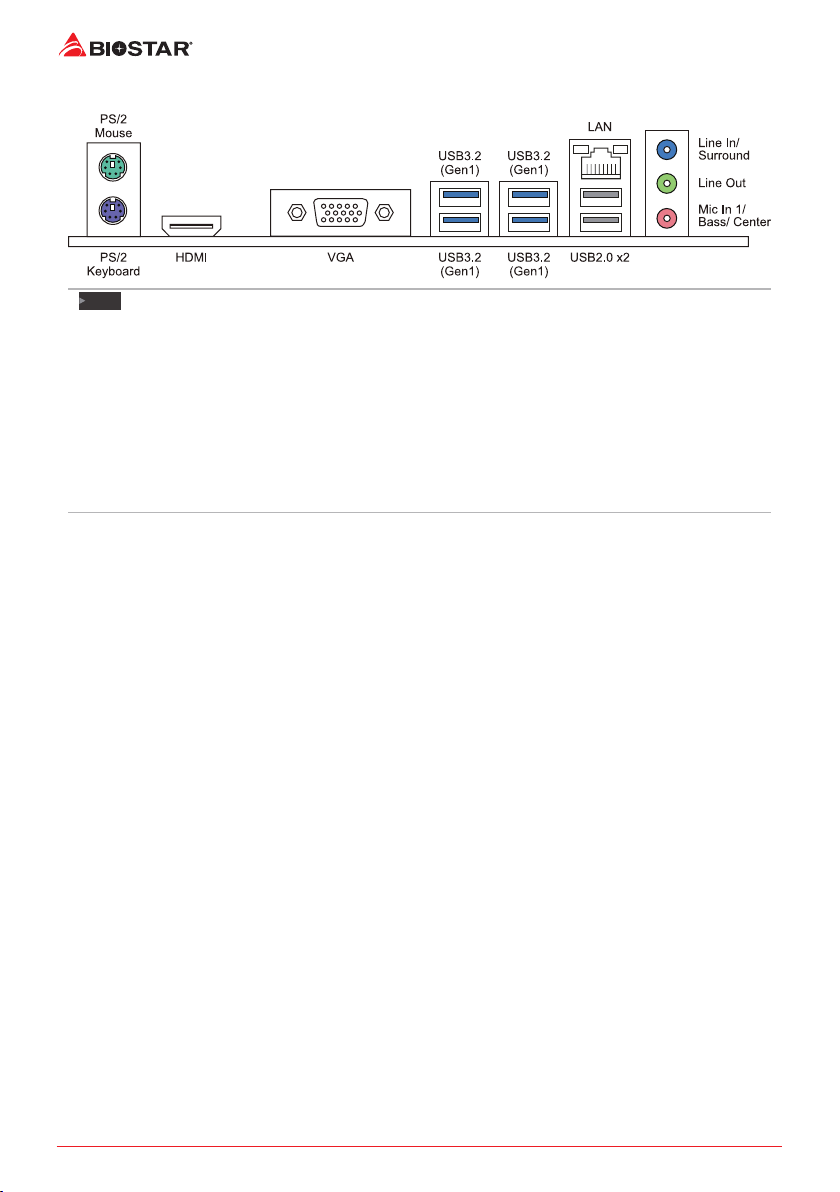
1.4 Rear Panel Connectors........................................................................................................ 6
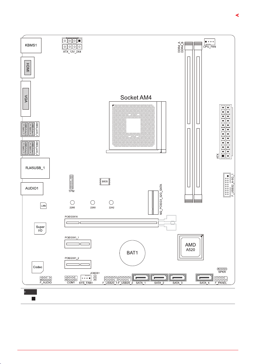
1.5 Motherboard Layout........................................................................................................... 7
Chapter 2: Hardware installaon����������������������������������������������������������������������������� 8
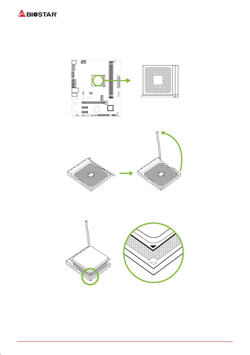
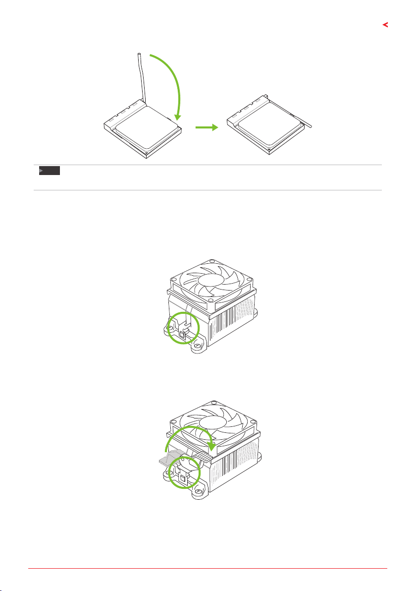
2.1 Install Central Processing Unit (CPU) .................................................................................. 8
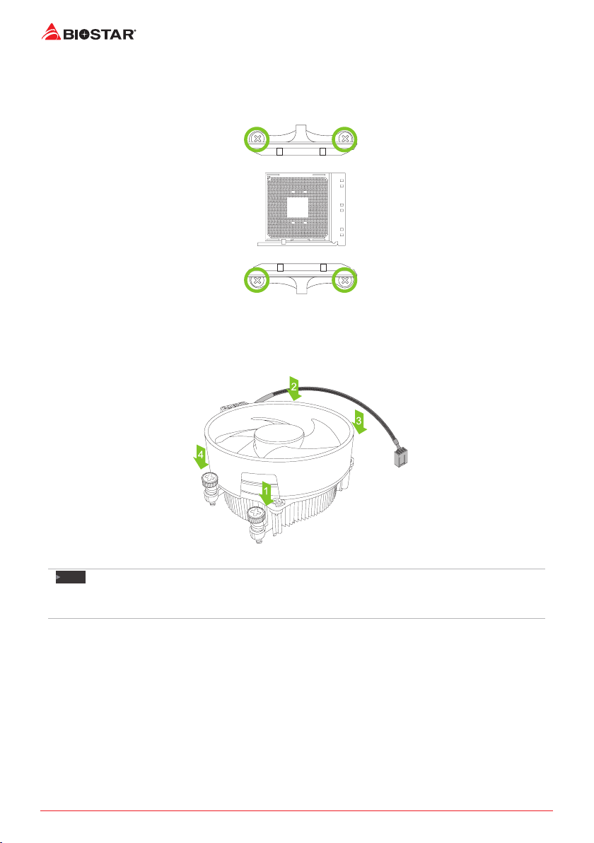
2.2 Install a Heatsink................................................................................................................. 9
2.4 Install System Memory ..................................................................................................... 12
2.5 Expansion Slots ................................................................................................................. 14
2.6 Jumper & Switch Seng................................................................................................... 16
2.7 Headers & Connectors...................................................................................................... 17
Chapter 3: UEFI BIOS & Soware��������������������������������������������������������������������������� 21
3.1 UEFI BIOS Setup................................................................................................................ 21
3.2 BIOS Update...................................................................................................................... 21
3.3 Soware............................................................................................................................ 25
Chapter 4: Useful help������������������������������������������������������������������������������������������� 26
4.1 Driver Installaon ............................................................................................................. 26
4.2 AMI BIOS Beep Code......................................................................................................... 27
4.3 AMI BIOS post code .......................................................................................................... 27
4.4 Troubleshoong................................................................................................................ 29
4.5 RAID Funcons.................................................................................................................. 30
APPENDIX I: Specicaons in Other Languages ����������������������������������������������������� 32
Arabic...................................................................................................................................... 32
German................................................................................................................................... 34
Spanish ................................................................................................................................... 36
Thai ......................................................................................................................................... 38
Japan....................................................................................................................................... 40

Chapter 1: Introducon | 3
A520MH 3.0
Chapter 1: Introducon
1�1 Before You Start
Thank you for choosing our product. Before you start installing the motherboard, please make
sure you follow the instrucons below:
• Prepare a dry and stable working environment with sucient lighng.
• Always disconnect the computer from power outlet before operaon.
• Before you take the motherboard out from an-stac bag, ground yourself properly
by touching any safely grounded appliance, or use grounded wrist strap to remove the
stac charge.
• Avoid touching the components on motherboard or the rear side of the board unless
necessary. Hold the board on the edge, do not try to bend or ex the board.
• Do not leave any unfastened small parts inside the case aer installaon. Loose parts
will cause short circuits which may damage the equipment.
• Keep the computer from dangerous area, such as heat source, humid air and water.
• The operang temperatures of the computer should be 0 to 45 degrees Celsius.
• To avoid injury, be careful of:
Sharp pins on headers and connectors
Rough edges and sharp corners on the chassis
Damage to wires that could cause a short circuit
1.2 Package Checklist
• Serial ATA Cable x2
• Rear I/O Panel for ATX Case x1
• Quick Installaon Guide x1
• Fully Setup Driver DVD x1
• M.2 Anchor x1
Note
»
»The package contents may be dierent due to the sales region or models in which it was sold. For
more informaon about the standard package in your region, please contact your dealer or sales
representave.

4 | Chapter 1: Introducon
1.3 Specifications
Specicaons
CPU Support
Socket AM4 support AMD® Ryzen™ 3rd Gen (Masse/ Renoir) and Ryzen™ 4th Gen
(Vermeer/ Cezanne) processors
Support for future AMD Ryzen processors with BIOS update
* Please refer to www.biostar.com.tw for CPU support list.
Chipset AMD®A520
Memory
4th Gen AMD® Ryzen Processors (Vermeer CPUs):
Supports Dual Channel DDR4 4400+(OC)/ 4000(OC)/ 3800(OC)/ 3600(OC)/ 3200/ 2933/ 2667/ 2400/
2133
4th Gen AMD® Ryzen with Radeon Graphics Processors (Cezanne APUs):
Supports Dual Channel DDR4 4933+(OC)/ 4800(OC)/ 4600(OC)/ 4400(OC)/ 4000(OC)/ 3800(OC)/
3600(OC)/ 3200/ 2933/ 2667/ 2400/ 2133
3rd Gen AMD® Ryzen Processors (Masse CPUs):
Supports Dual Channel DDR4 4400+(OC)/ 4000(OC)/ 3800(OC)/ 3600(OC)/ 3200/ 2933/ 2667/ 2400/
2133
3rd Gen AMD® Ryzen with Radeon Graphics Processors (Renoir APUs):
Supports Dual Channel DDR4 4933+(OC)/ 4800(OC)/ 4600(OC)/ 4400(OC)/ 4000(OC)/ 3800(OC)/
3600(OC)/ 3200/ 2933/ 2667/ 2400/ 2133
2 x DDR4 DIMM Memory Slot, Max. Supports up to 64 GB Memory
Each DIMM supports non-ECC 8/ 16/ 32 GB DDR4 module
* Please refer to www.biostar.com.tw for Memory support list.
Storage
-- Total supports 1x M.2 socket and 4 x SATA III (6Gb/s) ports
4x SATA III Connector (6Gb/s) : Supports AHCI & RAID 0, 1, 10
1x M.2 (M Key) Socket:
Supports M.2 Type 2242/ 2260/ 2280 SSD module
Supports PCI-E 3.0 x4 (32Gb/s) - NVMe/ AHCI SSD
Supports SATA III (6.0Gb/s) SSD
LAN Realtek RTL8111H
10/ 100/ 1000 Mb/s auto negoaon, Half / Full duplex capability
Audio Codec ALC897
7.1 Channels, High Denion Audio, Hi-Fi (Front)
USB 6x USB 3.2 (Gen1) port (4 on rear I/Os and 2 via internal headers)
6x USB 2.0 port (2 on rear I/Os and 4 via internal headers)
Expansion Slots
1x PCIe 3.0 x16 Slot:
Supports PCIe 3.0 x16 mode with AMD® Ryzen™ processors.
Supports PCIe 3.0 x16 mode AMD® Ryzen™ with Radeon Vega Graphics processors.
2x PCIe 3.0 x1 Slot
* According to dierent CPUs will have dierent speeds.
Rear I/Os
1x PS/2 Keyboard
1x PS/2 Mouse
1x HDMI Port
1x VGA Port
1x LAN port
4x USB 3.2 (Gen1) Port
2x USB 2.0 Port
3x Audio Jack
»
»Connued on Next Page

Chapter 1: Introducon | 5
A520MH 3.0
Specicaons
Internal I/Os
4x SATA III (6.0Gb/s) Connector
2x USB 2.0 Header (each header supports 2 USB 2.0 ports)
1x USB 3.2 (Gen1) Header (each header supports 2 USB 3.2 (Gen1) ports)
1x 8-Pin Power Connector
1x 24-Pin Power Connector
1x CPU Fan Connector
1x System Fan Connector
1x Front Panel Header
1x Front Audio Header
1x Internal Stereo Speaker Header
1x Clear CMOS Header
1x COM Port Header
1x TPM Header
Form Factor uATX Form Factor, 244 mm x 208 mm
OS Support Windows 10(64bit)/Windows 11(64bit)
Biostar reserves the right to add or remove support for any OS with or without noce.

6 | Chapter 1: Introducon
1.4 Rear Panel Connectors
Note
»
»HDMI/ VGA output require an AMD® family processor with intedrated graphics.
»
»Since the audio chip supports High Denion Audio Specicaon, the funcon of each audio jack
can be dened by soware. The input / output funcon of each audio jack listed above represents
the default seng. However, when connecng external microphone to the audio port, please use
the Line In and Mic In audio jack.
»
»Maximum resoluon
HDMI: 4096 x 2160 @24Hz, compliant with HDMI 1.4b
VGA: 1920 x 1200 @60Hz
»
»When using the front HD audio jack and plug in the headset, the rear sound will be automacally
Disabled.

Chapter 1: Introducon | 7
A520MH 3.0
1.5 Motherboard Layout
Note
»
» represents the 1st pin.

8 | Chapter 2: Hardware installaon
Chapter 2: Hardware installaon
2.1 Install Central Processing Unit (CPU)
Step 1: Locate the CPU socket on the motherboard
Step 2: Pull the socket locking out from the socket and then raise the lever up to a 90-degree
angel.
Step 3: Look for the white triangle on socket, and the gold triangle on CPU should point
towards this white triangle. The CPU will t only in the correct orientaon.

Chapter 2: Hardware installaon | 9
A520MH 3.0
Step 4: Hold the CPU down rmly, and then close the lever to locked the posion
Note
»
»Please turn o the Power Supply before remove the CPU socket.
2.2 Install a Heatsink
<TypeA>
Step 1: Place the heatsink and fan assembly onto the retenon frame. Match the heatsink clip
with the socket mounng-lug. Hook the spring clip to the mounng-lug.
Step 2: On the other side, push the retenon clip straight down to lock into the plasc lug on
the retenon frame, and then press down the locker unl it stops.

10 | Chapter 2: Hardware installaon
<TypeB>
Step 1: Remove the heatsink and fan assembly bracket on the motherboard and keep the
cooler backplane under the motherboard.
Step 2: Place the heatsink and fan assembly on top of the installed CPU and make sure that the
fan cable is closest to the CPU fan connector. Please refer diagram to the following screw into
the screw hole in the order shown.
Note
»
»Do not forget to connect the CPU fan connector.
»
»For proper installaon, please kindly refer to the installaon manual of your CPU heatsink.

Chapter 2: Hardware installaon | 11
A520MH 3.0
2.3 Connect Cooling Fans
These fan headers support cooling-fans built in the computer. The fan cable and connector
may be dierent according to the fan manufacturer.
CPU_FAN: CPU Fan Header
Pin Assignment
1 Ground
2+12V
3FAN RPM rate sense
4 AI Fan Control
SYS_FAN1: System Fan Header
Pin Assignment
1 Ground
2+12V
3FAN RPM rate sense
4 AI Fan Control
Note
»
»CPU_FAN, SYS_FAN1 support 4-pin and 3-pin head connectors. When connecng with wires onto
connectors, please note that the red wire is the posive and should be connected to pin#2, and the
black wire is Ground and should be connected to pin#1(GND).

12 | Chapter 2: Hardware installaon
2.4 Install System Memory
DDR4 Modules
Step 1: Unlock a DIMM slot by pressing the retaining clips outward. Align a DIMM on the slot
such that the notch on the DIMM matches the break on the slot.
Step 2: Insert the DIMM vercally and rmly into the slot unl the retaining clips snap back in
place and the DIMM is properly seated.
Note
»
»If the DIMM does not go in smoothly, do not force it. Pull it all the way out and try again.

Chapter 2: Hardware installaon | 13
A520MH 3.0
Memory Capacity
DIMM Socket Locaon DDR4 Module Total Memory Size
DDR4_A 8GB/16GB/32GB Max is 64GB.
DDR4_B 8GB/16GB/32GB
Dual Channel Memory Installaon
Please refer to the following requirements to acvate Dual Channel funcon:
Install memory module of the same density in pairs, shown in the table.
Dual Channel Status DDR4_A DDR4_B
Disabled O X
Disabled X O
Enabled O O
(O means memory installed, X means memory not installed.)
Note
»
»When installing more than one memory module, we recommend to use the same brand and
capacity memory on this motherboard.

14 | Chapter 2: Hardware installaon
2.5 Expansion Slots
PCIEG3X16: PCI-Express Gen3 x16 Slot
• PCI-Express 3.0 compliant. The maximum bandwidth of the PCIe slot is 32GB/s.
• Supports PCIe 3.0 x16 mode with AMD® Ryzen™ processors.
• Supports PCIe 3.0 x16 mode AMD® Ryzen™ with Radeon Vega Graphics processors.
PCIEG3X1_1/ PCIEG3X1_2: PCI-Express Gen3 x1 Slot
• PCI-Express 3.0 compliant.
• Data transfer bandwidth up to 1GB/s per direcon; 2GB/s in total.
M2_PCIEG3_32G_SATA: M.2 (M Key) Socket
• The M.2 slot supports M.2 Type 2242/2260/2280 SSD module. When installing M.2 SSD
module, please place the screw and hex pillar to correct posion.
• Support M.2 SATA III (6.0 Gb/s) module and M.2 PCI Express module up to Gen3 x4
(32Gb/s) - NVMe & AHCI SSD.
Note
»
»According to dierent CPUs will have dierent speeds.

Chapter 2: Hardware installaon | 15
A520MH 3.0
Install M.2 Anchor
1. Lock the M.2 Anchor into the motherboard hole which you use for type of M.2 SSD.
2. Insert the M.2 SSD into the M.2 socket.
3. Insert the pin on the M.2 Anchor into the hole on itself.
Install an Expansion Card
You can install your expansion card by following steps:
• Read the related expansion card’s instrucon document before install the expansion
card into the computer.
• Remove your computer’s chassis cover, screws and slot bracket from the computer.
• Place a card in the expansion slot and press down on the card unl it is completely
seated in the slot.
• Secure the card’s metal bracket to the chassis back panel with a screw. (This step is only
• for installing a VGA card.).
• Replace your computer’s chassis cover.
• Power on the computer, if necessary, change BIOS sengs for the expansion card.
• Install related driver for the expansion card.
Note
»
»Please be note that you will need to use M2 type screwdriver if you want to install or uninstall the
screw. It is recommended not to use a screwdriver that does not meet the specicaons, otherwise
the screw may be damaged.

16 | Chapter 2: Hardware installaon
2.6 Jumper & Switch Setting
The illustraon shows how to set up jumpers. When the jumper cap is placed on pins, the
jumper is “close”, if not, that means the jumper is “open”.
Pin opened Pin closed Pin 1-2 closed
JCMOS1: Clear CMOS Jumper
The jumper allows users to restore the BIOS safe seng and the CMOS data. Please carefully
follow the procedures to avoid damaging the motherboard.
Pin 1-2 Open:
Normal Operaon (default).
Pin 1-2 Short:
Clear CMOS data.
Clear CMOS Procedures:
1. Remove AC power line.
2. Set the jumper to “Pin 1-2 short”, you can use a metal object like a screwdriver to touch the
two pins.
3. Wait for ve seconds.
4. Aer clearing the CMOS values, be sure the jumper is “Pin 1-2 open”.
5. Power on the AC.
6. Load Opmal Defaults and save sengs in CMOS.

Chapter 2: Hardware installaon | 17
A520MH 3.0
2.7 Headers & Connectors
ATX: ATX Power Source Connector
For beer compability, we recommend to use a standard ATX 24-pin power supply for this
connector. Make sure to nd the correct orientaon before plugging the connector.
Pin Assignment Pin Assignment
13 +3.3V 1+3.3V
14 -12V 2+3.3V
15 Ground 3 Ground
16 PS_ON 4+5V
17 Ground 5 Ground
18 Ground 6 +5V
19 Ground 7 Ground
20 NC 8 PW_OK
21 +5V 9Standby Voltage+5V
22 +5V 10 +12V
23 +5V 11 +12V
24 Ground 12 +3.3V
ATX_12V_2X4: ATX Power Source Connector
The connector provides +12V to the CPU power circuit. If the CPU power plug is 4-pin, please
plug it into Pin 1-2-5-6 of ATX_12V_2X4.
Pin Assignment
1+12V
2+12V
3+12V
4+12V
5 Ground
6 Ground
7 Ground
8 Ground
Note
»
»Before you power on the system, please make sure that both ATX and ATX_12V_2X4 connectors
have been plugged-in.
»
»Insucient power supplied to the system may result in instability or the peripherals not funconing
properly. Use of a PSU with a higher power output is recommended when conguring a system with
more power-consuming devices.

18 | Chapter 2: Hardware installaon
F_PANEL: Front Panel Header
This connector includes Power-on, Reset, HDD LED and Power LED connecons. It allows user
to connect the PC case’s front panel switch funcons.
Pin Assignment Funcon Pin Assignment Funcon
1HDD LED(+) HDD
LED
2Power LED (+) Power
LED
3HDD LED(-) 4Power LED (-)
5 Ground Reset
Buon
6Power Buon Power-On
Buon
7 Reset Control 8 Ground
9NC NC 10 NA NA
SPKR: Chassis Speaker Header
Please connect the chassis speaker to this header.
Pin Assignment
1+5V
2N/A
3N/A
4Speaker
TPM: Trusted Plaorm Module Header
This header allows you to store cryptographic keys that protect informaon.
Pin Assignment Pin Assignment
1F_LAD0 2+3V
3F_LAD1 4+3V
5F_LAD2 6 TPM_24MHZ
7F_LAD3 8GND
9L_FRAME_N 10 NC
11 SER_IRQ 12 PLTRST_N
13 CLK_RUN_N 14 +3V3_DUAL

Chapter 2: Hardware installaon | 19
A520MH 3.0
SATA_1/ SATA_2/ SATA_3/ SATA_4: Serial ATA 6.0 Gb/s Connectors
These connectors connect to SATA hard disk drives via SATA cables.
Pin Assignment
1 Ground
2TX+
3TX-
4 Ground
5RX-
6RX+
7 Ground
F_USB32_A-5G_1: Header for USB 3.2 (Gen1) Ports at Front Panel
This header allows user to add addional USB ports on the PC front panel, and also can be
connected with a wide range of external peripherals.
Pin Assignment Pin Assignment
1VBUS0 11 D2+
2SSRX1- 12 D2-
3SSRX1+ 13 Ground
4 Ground 14 SSTX2+
5SSTX1- 15 SSTX2-
6SSTX1+ 16 Ground
7 Ground 17 SSRX2+
8 D1- 18 SSRX2-
9D1+ 19 VBUS1
10 ID 20 Key
F_USB20_1/ F_USB20_2: Header for USB 2.0 Ports at Front Panel
This header allows user to add addional USB ports on the PC front panel, and also can be
connected with a wide range of external peripherals.
Pin Assignment
1+5V (fused)
2+5V (fused)
3USB-
4USB-
5USB+
6USB+
7 Ground
8 Ground
9Key
10 NC

20 | Chapter 2: Hardware installaon
F_AUDIO: Front Panel Audio Header
This header allows user to connect the chassis-mount front panel audio I/O which supports HD
and AC’97 audio standards.
HD Audio AC’97
Pin Assignment Pin Assignment
1Mic Le in 1 Mic In
2 Ground 2 Ground
3 Mic Right in 3 Mic Power
4 GPIO 4 Audio Power
5 Right line in 5 RT Line Out
6Jack Sense 6RT Line Out
7Front Sense 7 Reserved
8Key 8Key
9Le line in 9LFT Line Out
10 Jack Sense 10 LFT Line Out
Note
»
»It is recommended that you connect a high-denion front panel audio module to this connector to
avail of the motherboard’s high denion audio capability.
»
»Please try to disable the “Front Panel Jack Detecon” if you want to use an AC’97 front audio output
cable. The funcon can be found via O.S. Audio Ulity.
COM1: Serial Port Connector
The motherboard has a serial port header for connecng RS-232 Port.
Pin Assignment
1 Carrier detect
2 Received data
3Transmied data
4 Data terminal ready
5Signal ground
6 Data set ready
7 Request to send
8 Clear to send
9 Ring indicator
10 Key
Table of contents
Languages:
Other Biostar Motherboard manuals

Biostar
Biostar IDEQ 220K User guide

Biostar
Biostar H110MDE User manual

Biostar
Biostar G41D3 Manual

Biostar
Biostar A58MDP User guide

Biostar
Biostar EIH81-IHP User manual

Biostar
Biostar B150GT5 User manual

Biostar
Biostar TP67B PLUS - BIOS User guide

Biostar
Biostar NF61S-M2 TE User guide

Biostar
Biostar P4M80-M7 User manual

Biostar
Biostar H110MGV3 User manual

Biostar
Biostar U8568 User guide

Biostar
Biostar P4M800-M7 A User manual

Biostar
Biostar M6TWG User manual

Biostar
Biostar H510MHP 2.0 User manual

Biostar
Biostar M6VCI User manual

Biostar
Biostar M7VIT Pro User guide

Biostar
Biostar M7 VKH User manual

Biostar
Biostar K8T890-A9 User manual

Biostar
Biostar Hi-Fi Z97Z5 User guide

Biostar
Biostar M6TLH Manual