Biral BTD-200 User manual

i
BTD-200 Accessory
Direction Finder
BTD-200 Accessory
Direction Finder


1
PROPRIETARY NOTICE
The information contained in this manual (including all illustrations, drawings,
schematics and parts lists) is proprietary to BIRAL. It is provided for the sole purpose
of aiding the buyer or user in operating and maintaining the sensor. This information is
not to be used for the manufacture or sale of similar items without written permission.
COPYRIGHT NOTICE
This document has been prepared by Bristol Industrial and Research Associates Limited
and contains copyright material belonging to the company.
No part of this manual may be reproduced without the express permission of BIRAL.
© 2019 Bristol Industrial and Research Associates Limited (BIRAL).
Manual Number: 107714
Revision: 00A
Biral –P O Box 2, Portishead, Bristol BS20 7JB, UK
Tel: +44 (0)1275 847787
Fax: +44 (0)1275 847303
www.biral.com

2
CONTENTS
1HOW TO USE THIS MANUAL................................................................... 4
2GENERAL INFORMATION ....................................................................... 5
2.1 Equipment covered in this manual ................................................................5
2.2 BTD-200 Direction Finder Description............................................................5
2.3 Customer Satisfaction ..................................................................................5
2.4 After Sales Support......................................................................................5
2.5 Contacting Biral...........................................................................................6
2.6 One year warranty.......................................................................................6
2.7 If you need to return the Direction Finder......................................................6
2.8 CE Certification............................................................................................7
2.9 Safety.........................................................................................................7
3SUPPLIED EQUIPMENT .......................................................................... 8
4SENSOR INSTALLATION ........................................................................ 9
4.1 Site Selection ..............................................................................................9
4.2 Mounting the Direction Finder..................................................................... 10
4.3 Connecting the Direction Finder.................................................................. 11
4.4 Setting Your Configuration ......................................................................... 12
4.5 Completing the Physical Installation ............................................................ 13
4.6 Software Compatibility & Updates ............................................................... 13
5USING THE DIRECTION FINDER .......................................................... 14
5.1 General .................................................................................................... 14
5.2 Flashes Without Direction........................................................................... 14
6MAINTENANCE..................................................................................... 15
6.1 Cables, Corrosion and Fasteners ................................................................. 15
6.2 General Cleaning ....................................................................................... 15
7ADJUSTING THE DIRECTION FINDER OFFSET ..................................... 16
7.1 Finding the Actual Lightning Direction ......................................................... 16
7.2 Entering the Direction Finder Offset ............................................................ 17
8SPECIFICATIONS ................................................................................. 18
8.1 Measurement ............................................................................................ 18
8.2 Power Requirements.................................................................................. 18
8.3 Environmental........................................................................................... 18

3
8.4 Certification and Compliance ...................................................................... 18
8.5 Physical .................................................................................................... 18
8.6 Maintenance ............................................................................................. 18
9INDEX .................................................................................................. 19
LIST OF FIGURES
Figure 4-1 Direction Finder Mounting .................................................... 10
Figure 4-2 Direction Finder Connection Terminals .................................. 11
LIST OF TABLES
Table 4-1 Configuration Switch Settings ................................................ 12

4
1HOW TO USE THIS MANUAL
The manual is organised so that if you read it from start to finish you will have a
good understanding of how the Direction Finder operates, how it should be installed
and how to use it. We realise however that different people will be involved in the
installation and use of the system, so the following guidance is given.
The BTD-200 Direction Finder is an accessory of the BTD-200 Lightning Warning
System, before attempting to install the Direction Finder we recommend you
familiarise yourself with the BTD-200 Lightning Warning System manual.
Physical Installation
Section 4, Sensor Installation, covers the physical installation of the system.
The installation will involve mounting the sensor outside on a pole and running
cables to a power source and your site warning system and/or IT system. A general
maintenance contractor or electrician will be able to do this work.
Software Update
Section 4.6, covers the software updates.
We have made the installation and update as easy as possible, so if you are
generally happy installing software applications the process should not be too
difficult.
Use and Maintenance
Section 5, describes how the Direction Finder operates within the BTD-200 system.
This section should be read by the person responsible for operating the system.
Maintenance requirements are discussed in Section 6, Maintenance.

5
2GENERAL INFORMATION
2.1 Equipment covered in this manual
BTD-200 Direction Finder Direction Finder accessory for the BTD-200 Lightning
Warning system
Part Number BA.024
2.2 BTD-200 Direction Finder Description
The BTD-200 Direction Finder allows the BTD-200 sensor to report the direction of
lightning flashes in addition to their distance from the sensor. The location of
lightning flashes is shown on the Lightning Works software map display as a series of
dots which fade with time. The Direction Finder thus allows the BTD-200 system to
provide a clear picture of the track of thunderstorms in the area.
2.3 Customer Satisfaction
At Biral we set our standards high and only your complete satisfaction is acceptable
to us. If you believe your experience has not met these standards, we would be
grateful if you would contact us, so we can discuss any issues you may have. We are
also pleased to hear of any positive experience.
2.4 After Sales Support
Biral offers support by telephone and email for the lifetime of our products, even if
there has been a change of ownership, so please get in touch if you require help.
Similarly, if you have any questions about your new equipment, we are only a
mouse-click or telephone call away. Our contact details are given below. For your
convenience our contact details are also on the label fixed to your equipment.

6
2.5 Contacting Biral
If you would like technical assistance, advice or you have any queries regarding the
operation of the sensor please do not hesitate to contact us.
Contact us by telephone on: + 44 (0)1275 847787
Contact us by fax on: + 44 (0)1275 847303
If you bought your system from a local agent, you may wish to contact them in the
first instance. No matter how you got your system Biral is here to help.
2.6 One year warranty
The BTD-200 Direction Finder comes with a one year limited warranty against
defective materials and workmanship. If you have any questions about the
warranty, please contact Biral.
To help us to assist you please be sure to include the following information:
-Model of equipment
-Serial number of equipment
-Nature of defect
-Your full name, address and contact details
2.7 If you need to return the Direction Finder
The BTD-200 Direction Finder should give you many years of trouble-free service but
in the unlikely event that the equipment proves to be faulty and we have asked you
to return the sensor to us please address the equipment to:
BIRAL
Unit 8 Harbour Road Trading Estate
Portishead
Bristol BS20 7BL
UNITED KINGDOM
The customer is responsible for the shipping costs.

7
2.8 CE Certification
All Biral’s BTD sensors comply with the requirements for CE marking. Once installed,
it is the user’s responsibility to ensure that all connections made to the equipment
comply with all Local and National safety requirements.
2.9 Safety
2.9.1 Operating Voltages
This product is intended for use with Non-Hazardous voltages only.
The Direction Finder power is taken directly from the BTD-200
Sensor. Any attempt to operate the Direction Finder from an
alternative power source will make the equipment potentially unsafe.
2.9.2 Inappropriate Use
Use of this product in a manner not described or specified in this
manual may result in the protection provided being impaired.

8
3SUPPLIED EQUIPMENT
The following equipment is supplied in the Direction Finder carton. Please check the
contents carefully and immediately report any missing items to your supplier.
Direction Finder, mounted on support arm with cable and U-bolt attached
2 Black nylon cable ties

9
4SENSOR INSTALLATION
The Direction Finder mounts to BTD-200 sensor mounting pole a little below the
sensor. If the Direction Finder is to be installed at the same time as the BTD-200
sensor it is recommended the physical installation of the BTD-200 sensor is
performed first. Once the BTD-200 sensor is installed the Direction Finder can be
fitted below the sensor before the system wiring is completed.
4.1 Site Selection
It is very important for the successful operation of the BTD-200 sensor and Direction
Finder that they are installed at a suitable site. For detailed information on site
selection for the BTD-200 sensor please refer to the BTD-200 system manual. Please
consider the following additional information when selecting your installation site for
systems with a Direction Finder:
No large ferrous metal objects within 20m (66’). See note 1.
No electrical power transformers or high voltage supply lines within 30m (98’).
No electric motors or motorised valves within 20m (66’).
No radio transmitters. See note 2.
No sources of radio frequency interference. e.g. electric arc welding
Note 1. Large ferrous metal objects and buildings with steel frames will distort the
local magnetic field which can cause the reported direction to have an offset error.
This error can be reduced as explained in section 7.
Note 2. The safe working distance between the Direction Finder and a radio
transmitter will depend on the transmission frequency and the strength of the signal.
For low to moderate power transmitters a separation distance of 20m (66’) is
recommended. For high power transmitters, especially at lower frequencies, a
greater distance may be required.

10
4.2 Mounting the Direction Finder
The Direction Finder is supplied attached to the mounting arm with the cable
attached. Mount the arm to the pole below the BTD-200 sensor using the supplied U-
bolt as shown in Figure 4-1 below. The top of the arm should be at least 260mm
(10.5”) below the sensor mount to allow room to lower the sensor enclosure for
access to the cable terminals.
Ensure the arrow on the side of the Direction Finder is pointing to True North.
If the Direction Finder is not accurately aligned to North, the reported lightning
location will not be correct.
Figure 4-1 Direction Finder Mounting
11
4.3 Connecting the Direction Finder
Remove the BTD-200 sensor outer cover following the instructions supplied in the
sensor manual.
Route the Direction Finder cable through one of the large cable glands on the
sensor’s base to the terminal board. Take care to avoid looping the cable around the
cover’s earth strap or you will not be able to refit the cover.
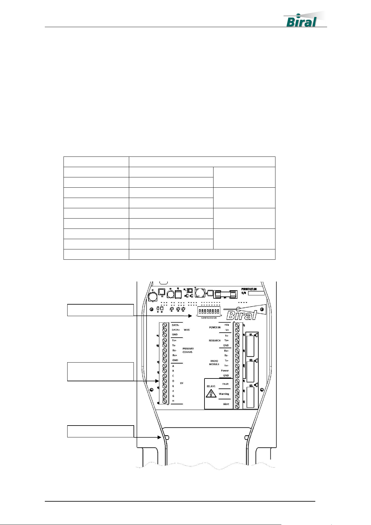
Connect the prepared end of the cable to the Direction Finder terminals shown in
Figure 4-2 and the table below.
Terminal
Wire Colour
A
Brown
Pair 1
B
Black
C
Orange
Pair 2
D
Red
E
Green
Pair 3
F
Yellow
G
Violet
Pair 4
H
Blue
Earth Stud
Cable screen with ring terminal
Direction Finder
Connection Terminals
Earth Stud
Figure 4-2 Direction Finder Connection Terminals
Configuration Switches

12
4.4 Setting Your Configuration
Before the BTD-200 sensor can operate with the Direction Finder you must set the
correct configuration on the Configuration Switches inside the BTD-200.
With the power to the BTD-200 disconnected or turned off and the outer cover
removed, locate the System Configuration switches on the terminal board. See Figure
4-2. The Configuration Switches are numbered 1 to 8 working from left to right.
When supplied all switches except number 1 will have the rocker pushed up in the
closed position, this is the default condition for the BTD-200 connected to a User
Computer and no other system components. Use Table 4-1, below, to set the switch
positions for the other components you have in your system. Work through the table
from switch 1 to 8 to ensure you have not missed either a component or a method of
connection. To select a system component or method of communication push the
rocker switch down to the open position.
Switch Number
1
2
3
4
5
6
7
8
User Computer
Fitted
BCB Fitted
WAS Fitted
BTD-200 has
Radio Module
User Computer or
BCB has Radio
Module
WAS has Radio
Module
WAS has wired
Connection to BCB
Direction Finder
Table 4-1 Configuration Switch Settings
For example, if you have a Direction Finder and your BTD-200 is connected to a
User Computer using a Radio Module and there are no other components, the
switches should be as follows:
Switch Number
1
2
3
4
5
6
7
8
Open
Closed
Closed
Open
Open
Closed
Closed
Open
If you add additional components to your system in the future, you will need to
update the configuration settings.

13
4.5 Completing the Physical Installation
When the steps described in sections 4.2 to 4.4 have been completed refit the BTD-
200 enclosure following the instructions given in the BTD-200 sensor manual.
Using the cable ties provided, secure the Direction Finder cable to the mounting pole
as shown in Figure 4-1.
The installation is now complete. Power to the BTD-200 can now be switched on.
4.6 Software Compatibility & Updates
When installing accessories for the BTD-200 it is recommended the BTD-200 sensor
software as well as the Lightning Works server and clients are updated to the latest
revision.
The latest revisions of software for all components of the BTD-200 system can be
downloaded for the Biral website at the following address:
https://www.biral.com/technical-support/downloads/software-downloads/
Each download includes step by step instructions to guide you through the software
update process.
Note: If your BTD-200 sensor is connected to a User Computer using a Radio
Module it will not be possible to update the sensor software. To update the sensor
software, it is necessary to have a wired connection between primary port and the
computer used to perform the software update.

14
5USING THE DIRECTION FINDER
5.1 General
After the Direction Finder has been installed and the system software has been
updated the BTD-200 system can be started and used in the normal manner.
5.1.1 Lightning Direction Display
When a Direction Finder is attached the Main tab of the Lightning Works client
display will have the distant and vicinity circles divided into eight equal segments.
When a lightning strike is detected which generates a Warning or Alert the segment
in which the lightning occurred will change colour. Additionally, a black dot will
appear to show the location of the lightning strike. The segment colour change will
remain until the Warning or Alert clears. The black dots representing the lightning
strikes will fade away over the time set by the Flash Display Setting on the User
Settings tab.
Located below the Map display area, the Flashes section displays the number of
lightning flashes detected for each range band in the last display period. The total
number of lightning flashes is displayed along with the number of lightning flashes
without direction information. The No Direction section is only displayed when a
Direction Finder is attached to the BTD-200. The Flashes section displays information
about all flashes in the last 60 minutes, this is the default period but can be changed
in the User Settings tab.
5.2 Flashes Without Direction
The BTD-200 sensor detects lightning flashes by observing changes in the
electrostatic field around the sensor whilst the Direction Finder detects the radio
waves emitted by a lightning flash. Lightning flashes can occur between the cloud
and the ground, between clouds or inside a cloud, these three types are often
referred to as Cloud to Ground, Cloud to Cloud and Intra Cloud. Cloud to Cloud and
Intra Cloud lightning flashes can be much weaker than Cloud to Ground flashes and
may not produce radio waves strong enough for the Direction Finder to detect. The
electrostatic measurement of the BTD-200 sensor is very sensitive to all types of
lightning flashes and so in some cases a flash will be detected but without any
direction information.
Lightning flashes without direction do not cause any part of the map display to
change colour but they are recorded in the Flashes section of the Main tab.
Lightning flashes without direction are used to generate Warnings and Alerts.

15
6MAINTENANCE
The BTD-200 Direction Finder requires no routine maintenance; however, it is
recommended the following checks are carried out at least annually to ensure your
system continues to work reliably.
6.1 Cables, Corrosion and Fasteners
The Direction Finder is made from glass reinforced plastic and stainless steel so
should not corrode; however, we recommend that all mounting hardware and
associated fasteners (nuts and bolts) are checked to ensure they are corrosion free
and tight.
Check the condition of the cable going to the BTD-200. Ensure the cable is secured
so it cannot be damaged by moving around in the wind.
6.2 General Cleaning
It is recommended that any heavy build-up of spider webs or dirt is removed from
the Direction Finder. This can be achieved with a brush and water hose as required.
Small amounts of detergent can be used to clean the sensor if desired but make sure
the sensor is thoroughly rinsed to remove all traces of detergent.

16
7ADJUSTING THE DIRECTION FINDER OFFSET
If the Direction Finder is not correctly aligned to True North or if there are local
distortions in the Earth’s magnetic field the reported direction may have an offset.
The offset is not usually large but may be noticeable when the map display is
compared to a lightning location network. The following sections describe how to
determine the size of the offset and apply a correction. Where the local magnetic
field is distorted the correction may not remove completely the offset for all reported
directions.
7.1 Finding the Actual Lightning Direction
There are several options to independently find the actual direction to lightning,
some of the best are detailed below. You can find the lightning direction reported by
the BTD-200 for each flash in the Activity Log section of the Main tab.
For all the methods discussed below, to increase confidence of the comparison
distances, it is best to compare many flashes and find a typical direction reported by
the BTD-200 Direction Finder and the independent method. Always make sure that
you are comparing lightning flashes detected by the BTD-200 and an independent
method which occurred at the same time.
7.1.1 National Lightning Location Network
Lightning detection by a national lightning location network is usually the best option
for locating lightning flashes as you can see individual flashes in near real-time. This
service can normally be found on your national weather service website or good
quality lightning data sites such as www.lightningmaps.org.
Identify individual flashes that are shown by both the BTD-200 and the lightning
location network and record the direction reported by the BTD-200 and the direction
from the BTD-200 to the flash as shown on the lightning location network. For best
results choose a small localised storm and average the BTD-200 direction and
lightning network direction for several flashes.
To determine the direction of the flash as reported by the lightning network it may
be necessary to printout the lightning network’s map display and then measure the
direction between North and flashes at the sensor’s location. The direction is
measured clockwise from North at the sensor’s location to the flash reported by the
lightning network.
Where possible combine the results from several storms in different directions
around the BTD-200. For each flash subtract the BTD-200 direction from the
lightning network direction. Calculate the average difference between the BTD-200
direction and that of the lightning network to obtain the offset value.

17
7.1.2 Rain Radar
If the storm is small and isolated, use an online rain radar site, normally available
from your national weather service, to find the heaviest precipitation. This is normally
where the lightning is found.
Average the direction reported by the BTD-200 for several lightning flashes and
estimate the direction from the BTD-200 location to the heart of the storm on the
rainfall radar. The direction is measured clockwise from North at the sensor’s location
to the flash reported by the lightning network. Subtract the average BTD-200
direction from the estimated direction taken from the rain radar to obtain the offset
value.
Where possible combine the results from several storms in different directions
around the BTD-200.
7.2 Entering the Direction Finder Offset
The Direction Finder offset is entered in the Direction Finder Offset section of the
Administrator tab of the Lightning Works client software. Details of how to enter the
offset are given BTD-200 sensor manual.

18
8SPECIFICATIONS
8.1 Measurement
Direction
Resolution 1°
8.2 Power Requirements
Supply Voltage
Powered by BTD-200 Sensor
Power Consumption
Less than 3 W (DC)
8.3 Environmental
Operating temperature
-20°C to 50°C
Relative humidity
0 to 100%
Protection rating
IP66
Wind speed
60 m/s
Altitude
-200m to 2,000m
Shock and vibration
Land based fixed installation
8.4 Certification and Compliance
CE marked
EMC
EN61326-1:2013 Industrial immunity,
industrial emissions
Compliance with EN50536:2011+A1:2012 for a Class 1 detector
Performs in accordance with IEC 62793 for a Class A detector
RoHS and WEEE compliant
8.5 Physical
Material
Stainless steel, glass filled epoxy plastic
Colour
Silver, grey
Weight
1.4kg, 3lbs Sensor and mounting bracket
Height
220mm, 8.6”
Width
90mm, 3.5”
Max Distance from mounting pole
centre
537mm, 21.1”
8.6 Maintenance
Selftest capability
Standard feature
Visual inspection
6 to 12 months
Warranty
1 year
Other manuals for BTD-200
4
Table of contents


