Bircher Reglomat Swissdoor ENT-R User manual

Safety edges
ENT-R, ENT-20, ENT-7, ENT-S
1
Safety edges
Assembly instructions
Application
Types of mounting1
Safety edges (sensors) in combination with a switching unit (signal processing) are components of a safety system (protection system for person detection).
The system, or more specically the safety edges, are used to safeguard shearing and crushing points on power-operated doors, gates and similar automatic
xtures. The safety edges can be installed in any horizontal or vertical position, either single or in combination.
Standard
Preparing the safety edge and assembling the contact strip2
Measuring the safety edge
2.1
Trim aluminium prole to the correct length and plan type of cable entry/exit, drill holes (countersunk) .
Trimming the rubber prole
2.2
L
L
5 – 8 mm
Using the rubber
shears, trim the rubber
prole to the desired
length L.
For the cable feed-through,
make a small hole (3,5 mm) with
hole punch pliers about
5 – 8 mm from the edge.
As an option for vertical applications
End caps on both ends
Trimming the contact strip2.3
L - X
Trim the contact strip to length (L – X). Be sure to cut at 90° angles!
The contact strip is shorter than the rubber prole
by the length of the end pieces used:
Cable and end piece Cable (both ends) Types
X = 55 mm 60 mm standard
X = 50 mm 55 mm vertical
ENGLISH
Bottom, rubber prole closed:
- 1 end cap
- Prole chamber sealed
Bottom, rubber prole open:
-no end cap
- switching chamber not sealed
Aluminium prole length = Rubber prole length (L)
267081C
04/15
Top, rubber prole closed:
- 1 end cap
- Prole chamber sealed
Top, rubber prole closed:
- 1 end cap
- Prole chamber sealed
The switching chamber for the contact strip must not be damaged unnecessarily as incoming water may impair the safety function
of the strip.

2
Crimping the end pieces
2.5
Using the crimping tool, crimp the end pieces at both ends and check they are secure.
Squeeze pliers rmly together.
Notice:
For contact strips ENT-R and ENT-20, end pieces ENEH-... must be crimped on with ES-PRESS
pliers (ClickLine, CoverLine and StandardLine).
For contact strips ENT-7 and ENT-S, use ENES-... end pieces and ESS-PRESS (S-Line) pliers.
Fitting the end pieces2.4
Measure off and mark a point exactly 10 mm from each end of the contact strip.
Then slide on the end pieces up to the marks (tolerance ±1 mm).
Testing the contact strip
2.6
Warning: The contact strip must be tested with an ohmmeter to ensure
correct functioning BEFORE it is tted in the rubber prole!
In the case of two-ended cables, test both ends!
Feeding in the contact strip
2.7
When feeding the contact strip into the rubber prole, no lubricants such as water, talc, oils,
greases or silicone spray, should be used.
Otherwise, the sealing compound applied later on will not bond with the rubber prole and seal
the switching chamber.
Notice: If the rubber prole is longer than 3 m, it is advisable to pass a length of string through
the prole rst using compressed air. Tie the string to the cable end of the contact strip and
then pull carefully the strip through. A stiff piece of wire is also a suitable aid. Be careful not to
damage the switching chamber when feeding the contact strip through!
Warning: Before sealing, check the functionality (contact-making) of the
safety edge again using an ohmmeter! In the case of two-ended cables,
test both ends!
ENT-R
ENT-20
ENT-7
ENT-S
Prole must be straight
ES-PRESS ESS-PRESS
End pieces
ENEH-8
ENES-8
ENEH-0
ENES-0
ENEH-K...
ENES-K...
8.1 - 8.5 kΩ ∞ ∞
< 500 Ω < 500 Ω < 500 Ω
a
b
2.4.1 Heat end pieces to 45 °C (if possible)
Notice: For proles EPE040/105 and EPE040/081, the arms must be folded up by 90 degrees
a before feeding the contact strip through in order to open up the switching chamber to
assist in assembly b.

3
3
Sealing the switching chambers in the rubber prole3.2
Standard
Prole
closed
End cap
NB: End cap only if rubber prole is sealed
Note:
For S-Line use ENS-parts instead of EN-parts
Assembling the safety edge
3
Types of mounting for the safety edge3.1
a Slide sealing plug EN-DL over cable, inserting at least
4 mm into the prole. Sealing plug EN-DS without hole
on the side without a cable.
b Wrap ES-BD sealing compound around cable and pull
through hole made with punch pliers using long-nosed
pliers. The hole must be completely sealed with the com-
pound.
c Then ll the rest of the switching chamber with sealing
compound and press down well.
Option for vertical applications
(sliding gates) only
End cap
approx.
2 cm Sealing compound
ES-BD
Fill rubber prole chamber
with sealing compound
ES-BD, at least 1 x 10 cm
(S-Line: 2 cm) strip.
EN-DL
Wrap half strip
of sealing
compound around
cable and pull through
hole. Hole must be
completely sealed!
Sealing compound
ES-BD
Sealing compound
ES-BD
Prole
Prole
Prole open
at bottom
EN-DL
EN-DL
Cable
Cable
EN-DS
approx.
1 cm
approx.
2 cm
Note: For ELE040/081 and ELE040/105: apply EN-KAS

Mounting the rubber prole 4.2
Moisten «click-t foot» rubber proles with a solution of soapy water and press into the
aluminium prole (do not pull in).
To ensure correct functioning of safety edges with a click-t foot, after moun-
ting, the safety edge must be pressed in along its entire length to make sure
the foot engages properly in the aluminium bar.
Otherwise, the safety edge will connect through. Check t of rubber prole in
aluminium strip.
2
2
Final checks4.3
Check the resistance of the safety edge with an ohmmeter.
Notice: The overall safety of the machine and its protection systems
depends on the quality, reliability and correct connection of the inter-
faces.
Warning: Perform a nal functional and visual check of the safety edge. Once mounting is complete, test the safety edge on
the object to make sure it functions correctly. The protection system must also satisfy the force, overtravel and sensitivity
requirements of the standards applicable in the relevant country.
The safety edge is maintenance-free. If damage occurs, such as a brittle or torn rubber prole, non-tight switching chamber, insucient contact
resistance in the activated state (>500 ohms) or similar, the safety edge must be replaced immediately. Please request a new one, remembering
to state the product designation.
Check the resistance of the safety edge with an ohmmeter, referring to the table above.
Maintenance
5
6Contact details
Manufacturer
Bircher Reglomat AG
Wiesengasse 20
CH-8222 Beringen
www.bircher-reglomat.com
Press in prole at both ends
Work from outside inwards
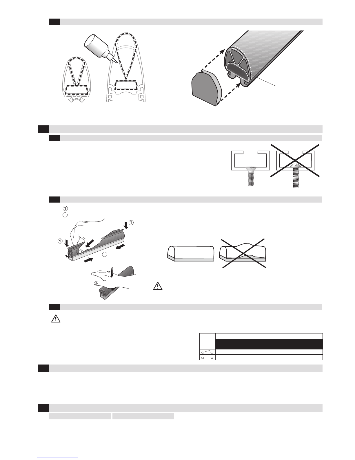
Glueing on the end caps3.3
ES-KLEBER
Attach end caps by applying ES-KLEBER to the points shown and hold in place, applying pressure across the whole area, for approx. 10 seconds.
Note: No end caps on ELE040/081 and ELE040/105
Attaching aluminium strip4.1
Attach aluminium strip to object with countersunk head screws. Recommended hole
spacing 300 mm. Make sure aluminium strip is securely attached to ends of safety edge.
You may have to make holes for the cable to exit.
NB: In the case of 2-panel systems, the two proles should be aligned facing each other.
The same applies to any counter sealing prole.
Notice: If possible, avoid routing the cable through the aluminium prole as it may press
against the switching chamber.
T-foot rubber proles should be pulled into the aluminium.
Any burrs on the aluminium prole must be removed rst.
End pieces
ENEH-8
ENES-8
ENEH-0
ENES-0
ENEH-K...
ENES-K...
8.1 - 8.5 kΩ ∞ ∞
< 500 Ω < 500 Ω < 500 Ω
Mounting the safety edge
4
c
c
Glue
4
Danish seller
Swissdoor ApS
Stenhuggervej 2
DK-5471 Soendersoe
Tlf.: +45 86 28 00 00
www.swissdoor.dk
This manual suits for next models
3
Table of contents
Popular Controllers manuals by other brands

IDEC
IDEC HS9Z-FL54 manual

tbs electronics
tbs electronics Omnicharge Solar OCS 100-20 owner's manual

TAC
TAC GUITAR MANIA Usage instructions

BRV
BRV ModvlvS M21 manual

AUMA
AUMA SAEx 25.1 Operation instructions

Mitsubishi Programmable Controllers
Mitsubishi Programmable Controllers ENHANCED F2 Series instruction manual

ABB
ABB ACS580-07-0495A-4 Hardware manual

Johnson Controls
Johnson Controls tyco PowerSeries Neo Reference manual

Balboa
Balboa Mach 2.1 EL Series Installation and configuration guide

Zener
Zener SMARTSTART 6000 Networking guide

Distech Controls
Distech Controls DA-020S230DX installation instructions

Mente Marine
Mente Marine ACS A user manual