Bird Electronic 8138 User manual

INSTRUCTION MANUAL
DUMMY LOAD
Coaxial Load Resistor
MODEL 8138
General Dynamics Drawing No. A16071
LITHO IN U.S.A.
BIRD ELECTRONIC CORP.
CLEVELAND, OHIO


TABLE OF CONTENTS
Paragraph Page
SECTION I. INTRODUCTION AND DESCRIPTION
1-1. Scope
1-3. Purpose ..
1-5. Leading Particulars
1-7. Description
1-
11. Theory of Operation
SECTION II. PREPARATION FOR USE
2-
1. General .
2-
3. Installation ..... .. . •.... ..
SECTION m. OPERATING INSTRUCTIONS
3-
1. General .
3-3. Transmitter Loading
3-
5. Loss Measurement and VSWR Measurement of Insertion ...
Components
SECTION IV. MAINTENANCE INSTRUCTIONS
4-
1. General .......... ....
4-3. Gleaning
4-
5. Checking VSWR
SECTION V, TROUBLESHOOTING
5-
1. Troubleshooting Chart •
SECTION VI. REPAIR INSTRUCTIONS
6-
1. General
6-3. Disassembly ..............
6-5. Cleaning and Inspection
6-
7. Reassembly
SECTION VII. REPLACEMENT PARTS LIST
7-
1. Parts List
1
1
1
1
2
3
3
4
4
4
4
4
4
5
6
6
6
7
8

Figure 1-1. Model 8138 Dummy Load
1

SECTION I
INTRODUCTION AND DESCRIPTION
1-1. SCOPE
1-2. This technical manual provides adescrip-
tion, installation and maintenance instructions,
suggested uses, and other pertinent information
for the Model 8138 Dummy Load, manufactured
by Bird Electronic Corporation, Cleveland
(Solon), Ohio, for General Dynamics, their
drawing number A16071. (See figure 1-1.) This
manual is intended for use by the technicians
who are responsible for the operation and main-
tenance of this equipment.
1-3. PURPOSE
1-4. The Model 8138 dummy load is aresistor
designed to match 50- ohm coaxial lines. It is
used primarily for transmitter loading, conven-
iently dissipating transmitter power to replace
an antenna during transmitter tuning. In this
application it provides an almost purely re-
sistive load, independent of frequency. It is
also used for insertion loss measurement of
connectors, cables, filters, and similar compo-
nents. It is used as aerospace ground equipment
in support of the F-lllA/B.
1-5. LEADING PARTICULARS
1-6. Leading Particulars for the Model 8138
Dummy Load are given in Table I.
1-7. DESCRIPTION
1-8. The Model 8138 Dummy Load is ametallic
film on Pyrex glass cylindrical resistor which
is immersed in adielectric coolant. The re-
sistor and coolant are confined in aconical
internal housing which provides proper charac-
teristics for good coaxial line termination.
Table I. Leading Particulars
Wattage Rating (Continuous)
Characteristic impedance -•^g^^ss
Rated Frequency Range" !225 -400 megacycles/sec
VSWR (Voltage Standing Wave Ratio)
Line Con^e^orSd Female type
Optional Any common RF type
Amblert 0to *55'C (t-32 loblSl" F)
S-SKeraiing -»8«o *«-c <-» to f>
Non-Operating Sea Level to 50,000 ft
Relative Humidity Range *np;c;°r’
Operating (max.) -95 percent at 0o+55 C
Non-Operating (max.) 190 percent at -62 to +8 C
Coolant ^Transit Dielectric Oil
Volume 4/5 pt
Basic Overall Dimensions
Width 3-15/16 in.
Height (handle retracted) g'si/M in
^6lbs
Weight
1

Cooling fins are provided on the housing to help
dissipate resistor heat to the surrounding at-
mosphere. Asynthetic rubber bellows is mounted
on the back to compensate for changes in oil
volume caused by temperature changes of the
coolant. Avented metal cap protects the bel-
lows from damage.
CAUTION
Do not probe the vent hole of the dia-
phragm cap with asharp-pointed instru-
ment or the diaphragm may be damaged.
1-9. Ascrew-type coaxial cable connector is
provided at the front of the dummy load to
facilitate making line connections. The standard
model is equipped with aFemale ''N" type con-
nector. This mates with the Male type plug
of RG-8A/U and RG-9B/U type cables. If
another type of connector is required, sub-
stution can be made by removing the four No.
8-32 round-head machine screws that secure
the connector flange to the face of the load
resistor. Pull straight out on the connector to
remove it. Anew connector can be installed
by reversing the removal procedure. Alternate
quick-change connectors are available from Bird
Electronic Corporation.
1-10. The load rests on four rubber bumper
feet. These feet can be removed to provide
threaded holes for rigid mounting of the unit.
1-11. THEORY OF OPERATION
1-12. The dummy load consists of ametallic
film on Pyrex glass cylindrical resistor mounted
in an oil-filled housing. The resistor is ter-
minated with acoaxial connector which extends
from the housing. Within the housing the re-
sistor is mounted in aconical internal housing
which helps to provide the proper electrical
characteristics for coaxial line termination.
1-13. When aload is applied to the resistor,
the resistor converts the electrical input into
heat which must be dissipated to prevent the
parts from overheating. The heat generated in
the resistor is absorbed by the dielectric oil
which surrounds the resistor. The specific
gravity of the heated oil is less than that of
the cool oil, and the heated oil rises, causing
convection currents to flow within the housing.
The tapered end of the conical housing has
three slots top and bottom, and the wide end has
one round hole top and bottom to facilitate oil
circulation through the conical housing and
around the resistor. As the convection currents
flow through the outside housing, the hot oil
contacts the metallic housing, transferring the
heat to the housing to cool the oil. The external
housing has cooling fins which help dissipate
the heat to the atmosphere. This system operates
as long as the load continues to be dissipated
into the resistor.
1-14. When the oil heats, it expands and re-
quires agreater volume. This expansion is
compensated for by asynthetic rubber diaphragm
installed at the rear of the load, which accom-
modates the extra volume. The diaphragm is
protected by aspun metal cover. The cover at
the rear of the load and the resistor assembly
at the front of the load are retained by circular
V-clamps.
2

SECTION II
PREPARATION FOR USE
2-1. GENERAL
2-2. Model 8138 Dummy Load as received is
ready for operation. It has been factory filled
to the required coolant level with approximately
4/5 pint of GE Type IOC Transit Dielectric
Oil at room temperature. Upon receipt, check
for oil loss. Afew drops of oil loss will not
impair the efficiency of the equipment, but losses
greater than 10 percent may impair the opera-
tion, since cooling characteristics are important
to maintaining proper RF impedance and power
rating.
2-3. INSTALLATION
2-4. The following considerations should be
made when installing the Model 8138 Dummy
Load.
of free air space around and above the unit to
enable free air circulation necessary for cool-
ing. The dummy load will rest on its four
rubber feet.
c. If fixed mounting is desired, remove the
four rubber bumper feet to provide mounting
holes for mounting. Refer to figure 2-1 for
mounting dimensions.
CAUTION
Do not operate the dummy load with the
input connector pointing up. This will
prevent coolant from reaching the input
section of the dummy load and will
greatly disturb the RF impedance.
a. The unit has been designed to be operated
with the carrying handle positioned on the top.
If the dummy load is laid on either side, the
termination properties will not be impaired, but
the load power capacity will be reduced by a
considerable amount. This is due to the re-
stricted circulation of coolant when it is tipped.
b. Mount the dummy load on any convenient
flat surface. Make sure there is several inches
d. If the particular installation requires a
different type of coaxial connector, the connector
is easily replaced with adifferent type by re-
moving the four machine screws that secure the
connector to the dummy load and pulling straight
out to remove it. Install the correct connector
by reversing the removal procedure. Connect
the coaxial cable to the dummy load. Alternate
connectors are available from the manufacturer.
Figure 2-1. Mounting Dimensions
3
SECTION III
OPERATING INSTRUCTIONS
3-1. GENERAL
3-2. The dummy load has no switches, controls,
or indicators which the operator must mani-
pulate or watch. It must be used only in the
manner for which it was intended. Make sure
it is used only on 50- ohm RF lines within the
power limits for which it is rated. Some of the
most frequently used applications are given
below.
CAUTION
When the dummy load is operated at
close to its rated capacity for an ex-
tended period, the exterior housing will
become hot enough to cause burns. Take
care not to touch the metal under these
conditions.
3-3. TRANSMITTER LOADING
3-4. In this application, it is necessary only to
connect the load to the transmitter line. It
will provide astandardized load resistance with-
in its rating, dissipating the power in the form
of heat.
3-5, LOSS MEASUREMENT AND VSWR MEA-
SUREMENT OF INSERTION COMPONENTS
3-6. Loss measurements and VSWR measure-
ments of insertion components such as con-
nectors, filters, and cables can be made by
comparing measurements with and without the
component installed in aline terminated by the
dummy load. Highly accurate measurements of
this type can be made when aBird Model 43
Thruline Wattmeter is used in conjunction with
the dummy load.
SECTION IV
MAINTENANCE INSTRUCTIONS
4-1. GENERAL
4-2. Maintenance is normally restricted to
cleaning the exterior of the instrument and to
checking to assure that it is operating within
the required VSWR limits. Because of its
simple, rugged construction it requires little
care.
4-3. CLEANING
4-4. Wipe all dust and grime from the exterior
of the housing. Remove any greasy or gummy
deposits with acloth dampened with trichloro-
ethyline, Federal Specification 0-Y-236a. Clean
the connector contact and face with acotton
swab stick dampened with trichloroethylene.
4-5. CHECKING VSWR
4-6. To determine if the dummy load is oper-
ating satisfactorily, check the VSWR of the unit.
This can be done very simply by use of aBird
Thruline Model 43 Wattmeter. If the VSWR ex-
ceeds 1.1 when measured in the rated wattage
and frequency range, it will be necessary to
replace the resistor assembly. Refer to para-
graph 6-4.
4

SECTION V
TROUBLESHOOTING
5-1. TROUBLESHOOTING CHART
5-2. Table Hprovides alist of the most prob-
able troubles which might occur in the load.
For each trouble there is alist of probable
causes and remedies.
Table II. Troubleshooting Chart
TROUBLE PROBABLE CAUSE REMEDY
VSWR EXCEEDS 1.1 Poor connections. Clean connectors.
Tighten securely.
Defective resistive element. Replace resistive
element.
UNIT LEAKS OIL Defective O-ring. Disassemble and replace
O-ring.
Punctured diaphragm. Disassemble and replace
diaphragm.
UNIT OVERHEATS Excessive load. Remove excessive load.
Unit not in upright Set in upright position
position. with handle on top.
Insufficient coolant. Add dielectric oil to
required level.
Resistor assembly not Disassemble and position
properly oriented in resistor assembly so
housing. that coolant slots are
at top and bottom.
5
SECTION VI
REPAIR INSTRUCTIONS
6-1. GENERAL
6-2, Repair is normally limited to parts re-
placement. Do not disassemble unless trouble-
shooting indicates the necessity of parts re-
placement. To replace parts, disassemble and
reassemble only to the extent required as di-
rected below.
6-3. DISASSEMBLY
6-4. Disassemble the dummy load as follows:
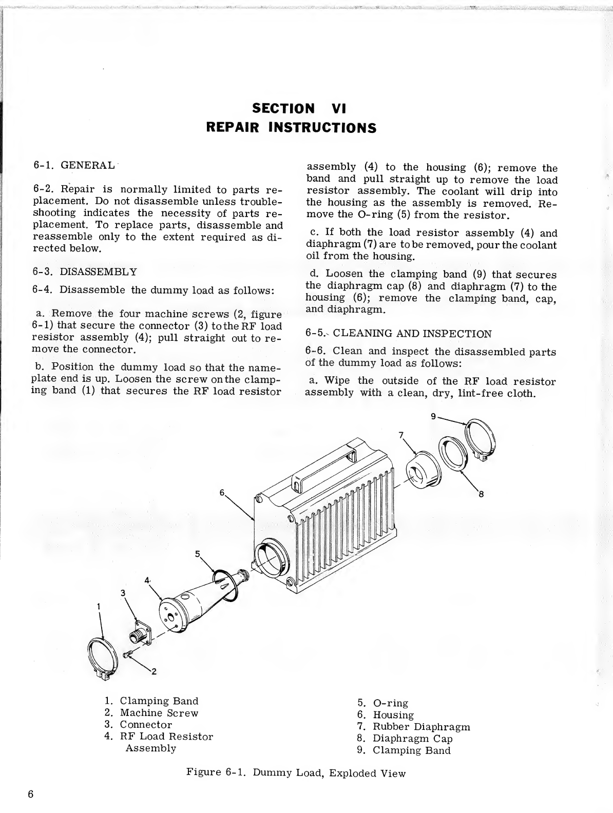
a. Remove the four machine screws (2, figure
6-1) that secure the connector (3) to the RF load
resistor assembly (4); pull straight out to re-
move the connector.
b. Position the dummy load so that the name-
plate end is up. Loosen the screw on the clamp-
ing band (1) that secures the RF load resistor
assembly (4) to the housing (6); remove the
band and pull straight up to remove the load
resistor assembly. The coolant will drip into
the housing as the assembly is removed. Re-
move the O-ring (5) from the resistor.
c. If both the load resistor assembly (4) and
diaphragm (7) are to be removed, pour the coolant
oil from the housing.
d. Loosen the clamping band (9) that secures
the diaphragm cap (8) and diaphragm (7) to the
housing (6); remove the clamping band, cap,
and diaphragm.
6-5.^ CLEANING AND INSPECTION
6-6. Clean and inspect the disassembled parts
of the dummy load as follows:
a. Wipe the outside of the RF load resistor
assembly with aclean, dry, lint-free cloth.
1. Clamping Band
2. Machine Screw
3. Connector
4. RF Load Resistor
Assembly
5. O-ring
6. Housing
7. Rubber Diaphragm
8. Diaphragm Cap
9. Clamping Band
Figure 6-1. Dummy Load, Exploded View
6

b. Wipe the O-ring and diaphragm with acloth.
c. Clean all remaining metallic parts with
trichloroethylene, Federal Specification O-Y-
236a. Dry thoroughly, taking care to remove all
traces of solvent from the inside of the housing.
d. Inspect the O-ring and diaphragm for cracks,
scoring, deterioration, and other damage; re-
place damaged parts.
e. If predisassembly troubleshooting indicated
that the RF load resistor assembly was not
performing within required limits, replace it.
f. Inspect the housing for cracks, broken cool-
ing fins, damaged clamping band seats, and other
damage; replace adamaged housing.
g. Replace other parts that are cracked, dis-
torted, or otherwise damaged.
6-7. REASSEMBLY
6-8. Reassemble the dummy load as follows:
a. Position the rubber diaphragm (7, figure 6-1)
on the housing (6) so that the projecting end
enters the housing. Position the diaphragm cap
(8) on the housing and secure the parts with the
clamping band (9).
b. Position the housing so that the nameplate
end is up. Fill the housing to the required level
with GE Type IOC Transit Dielectric Oil (ap-
proximately 4/5 pint at room temperature).
c. Install the O-ring (5) on the RF load re-
sistor assembly (4). Position the load resistor
assembly so that it is fully seated in the hous-
ing. Make sure that the slotted holes on the
tapered end of the conical housing and the
round holes at the wide end of the conical
housing are positioned top and bottom.
CAUTION
Failure to orient the RF load resistor
assembly correctly in the housing will
result in obstructed coolant flow and
may affect the power rating and RF
impedance.
d. Secure the RF load resistor assembly (4) to
the housing with the clamping band (1). Tighten
the screw on the clamping band.
e. Position the connector (3) on the front of
the RF load resistor assembly (4); secure with
four machine screws (2),
f. After reassembly, check the dummy load for
coolant leaks. If coolant is leaking from around
the clamping bands, tighten the band screw and
check if the leaking stops. If it does not, re-
place the O-ring (5) or the diaphragm (7).
g. Check the VSWR of the dummy load by con-
necting it, along with aBird Model 43 Thruline
Wattmeter, to aproperly rated 50- ohm trans-
mission line. VSWR must not exceed 1.1.

SECTION VII
REPLACEMENT PARTS LIST
I
\
\
7-1. PARTS LIST
7-2. Alist of replaceable parts for the dummy
load is given below. Use the exploded view of
figure 6-1 for parts identification.
Index No.
Fig. 6-1 Bird
Part No. Nomenclature Qty
Reqd
1750254 BAND ASSEMBLY, Clamping 1
2COML SCREW, Machine, Rd hd, No. 8-32 x1/4 in., ..4
brs, sil pi
3424062 CONNECTOR, Female Ntype 1
4813002 RESISTOR ASSEMBLY, RF load 1
55229 O-RING 1
6NSS* HOUSING 1
724015 DIAPHRAGM 1
824050 CAP, Diaphragm 1
9750254 BAND ASSEMBLY, Clamping 1
N.I./ 5030 OIL, GE Type IOC Transit Dielectric 1pt
*Not Sold Separately
4-Not Illustrated
8
Table of contents
Other Bird Electronic Measuring Instrument manuals


Popular Measuring Instrument manuals by other brands


Rohde & Schwarz
Rohde & Schwarz ZVA8 operating manual

Compressed Air Alliance
Compressed Air Alliance FLP user manual

Boumatic
Boumatic TouchPoint OPERATION, SERVICE AND MAINTENANCE INSTRUCTIONS

OKOndt GROUP
OKOndt GROUP UTG-8 quick start guide

Test Equipment Depot
Test Equipment Depot SBS 2500 manual
Fluke
Fluke Datapaq Furnace Tracker user manual

Ametek Land
Ametek Land CYCLOPS L quick start guide

Triplett
Triplett CableRater instruction manual

Crowcon
Crowcon SprintPro 3 user manual

Noding
Noding PM 82 operating instructions

Makita
Makita SK106D manual

Dwyer Instruments
Dwyer Instruments DigiMag DM-1200 Series Specifications-installation and operating instructions