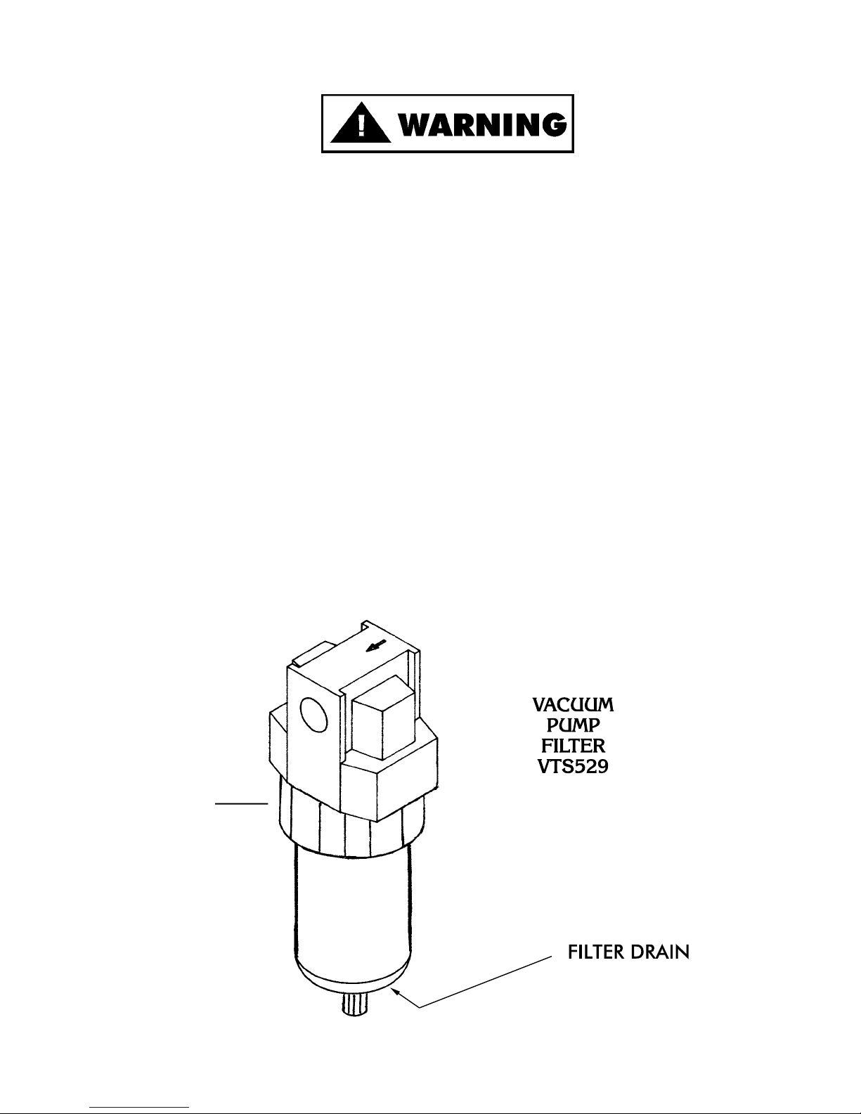
BIRO VTS-100 User manual

MODEL VTS-100
VACUUM TUMBLER
OPERATION MANUAL & PARTS LIST
STARTING WITH SERIAL NO. VT4
The BIRO VTS-100 VACUUM TUMBLERS are versatile machines used for vacuum
tumbling all types of meats with marinaded blends of herbs and spices. All marinades
should be FDA approved and meet F.S.I. standards. The BIRO VTS-100 produces
equally impressive results with beef, pork, poultry and fish.
The unit is both easy to clean and maintain as well as sanitary in design and con-
struction. The entire machine is built to give many years of trouble free service while
providing a unique line of marinated products for your customers.
ITEM No. VTS100-324

TABLE OF CONTENTS
Page
NOTICETOOWNERSANDOPERATORS......................................... 1
SAFETYTIPS............................................................... 2
OPERATION................................................................ 3
CLEANING................................................................. 4
MAINTENANCE ............................................................. 5
VACUUMPUMPFILTER................................................ 5,6,7
VACUUMPUMP........................................................ 8,9
LUBRICATION & MAINTENANCE FOR GEAR REDUCER . . . . . . . . . . . . . . . . . . . . . . . 10,11
PHOTOELECTRIC EYE OPERATING INSTRUCTIONS . . . . . . . . . . . . . . . . . . . . . . . . . 12,13
CONTROLPANEL–COMPONENTS .........................................14
CONTROLPANEL–REARVIEW.............................................15
DRUMASSEMBLY ...........................................................16
FRAMEASSEMBLYANDCOMPONENTS..........................................17
VACUUMHOSESANDFITTINGS.............................................18,19
COMPONENTCOVERANDREARDOOR .........................................20
WIRINGDIAGRAMS .......................................................21,22
RECOMMENDEDSPAREPARTS ................................................23
OPERATOR'SNOTES.........................................................24
OPERATOR’SSIGNATUREPAGE................................................25
LIMITEDWARRANTY.........................................................26

BIRO’s products are designed to process food products safely and efficiently. Unless the oper-
ator is properly trained and supervised, however, there is the possibility of a serious injury. It is the
responsibility of the owner to assure that this machine is used properly and safely, strictly following
the instructions contained in this Manual and any requirements of local law.
No one should use or service this machine without proper training and supervision. All opera-
tors should read and be thoroughly familiar with the procedures contained in this Manual. Even so
BIRO cannot anticipate every circumstance or environment in which its products will be used.
You, the owner and operator, must remain alert to the hazards posed by the function of this equip-
ment. No one under eighteen (18) years of age should operate this equipment. If you are uncer-
tain about a particular task, ask your supervisor.
This Manual contains a number of safe practices in the SAFETY TIP section. Additional warn-
ings are placed throughout the Manual. Warnings related to your personal safety are indicated by:
Warnings related to possible damage to equipment are indicated by:
BIRO also has provided warning labels on the equipment. If any warning label, instruction label
or Manual becomes misplaced, damaged, or illegible, please contact your nearest Distributor or
BIRO directly for a replacement.
Remember, however, this Manual or the warning labels do not replace the need to be alert and
to use your common sense when using this equipment.
1
NOTICE TO OWNERS AND OPERATORS
OR
–NOTE –
Acopy of this manual is included with each Model VTS-100 Vacuum Tumbler.
The descriptions and illustrations contained in this manual are not binding.
The manufacturer reserves the right to introduce any modification without
updating the manual.

SAFETY TIPS
ROTATING DRUM
TO AVOID SERIOUS PERSONAL INJURY
NEVER Touch This Machine Without Training and Authorization By Your Supervisor.
ALWAYS Read Operation and Service Manual BEFORE Operating, Cleaning or Servicing.
ALWAYS Keep Hands Clear of the Rotating Drum and Other Moving Parts.
NEVER Attempt to Remove the Drum Lid Unless Vacuum Has Been Released and the Drum is
Positioned Vertically With the Lid at the Top.
NEVER Operate Vacuum Pump Unless Properly Connected to Tumbler Drum.
ONLY Operate Vacuum Pump in Recommended Vacuum Range (15-20 Inches of Mercury)
NEVER TO EXCEED 20 INCHES Hg.
ONLY Use a Qualified Electrician to Install According to Local Building Codes: Machine MUST
Be Properly Grounded.
ONLY Install on Level, Non-Skid Surface in a Clean, Well-Lighted Work Area Away From
Children and Visitors.
DO NOT Allow Food Particles, Liquids or Any Other Foreign Material to Enter the Vacuum
Pump or Vacuum Hose.
ALWAYS Turn Off, Unplug From Power Source and Perform Lockout/Tagout Procedure to This
Machine BEFORE Cleaning or Servicing.
NEVER Leave Machine Unattended While Operating.
PROMPTLY REPLACE Any Worn or Illegible Warning and/or Instruction Labels.
USE ONLY BIRO Parts and Accessories Properly Installed.
FOOD HANDLING TO PREVENT CONTAMINATION
1. ALWAYS wash hands thoroughly with warm soap and water before and after handling raw fish, poultry or
meats.
2. ALWAYS clean and sanitize all utensils and surfaces that have been in contact with raw products.
3. ALWAYS store cold foods at or below 45 deg. F (7.2 deg. C).
2

OPERATION
ROTATING DRUM
ONLY Properly Trained Personnel Should Use This Equipment.
ALWAYS Keep Hands Clear of the Rotating Drum and Other Moving Parts.
DO NOT Tamper With, Bypass, Alter, or Modify This Equipment in Any Way From Its Original
Condition.
ALWAYS Turn Off, Unplug From Power Source and Perform Lockout/Tagout Procedure to This
Machine Before Cleaning, Servicing, or When Not In Use.
NEVER Leave Unattended While Operating.
NEVER Turn Drum by Hand, Jog Machine Until Drum is in Desired Position.
ALWAYS Comply With All Regulation for Food Handling, Packaging, and Storage.
NEVER Operate Without All Warning or Instruction Labels Attached.
TO PROCESS PRODUCT
1. Weigh product to be vacuum tumbled.
2. Refer to your ingredient chart for proper amount of marinade seasoning and water.
3. Use jog switch to position drum opening upright.
4. Place product, marinade and water into tumbler drum.
5. Install gasket on drum and place cover on drum and secure with four latches.
6. Connect vacuum hose to valve on drum. Be sure valve handle is in the open position, Parallel with the valve
body.
7. Turn vacuum pump to “ON”. (Vacuum gauge will start indicating a vacuum is being pulled in the drum.) If
needle in vacuum gauge does not indicate vacuum is being pulled, turn “OFF” vacuum pump and
disconnect vacuum hose from drum lid. Remove drum lid and check that the lid gasket is properly installed
and seated, then repeat this procedure.
8. When vacuum gauge does indicate that a vacuum is being pulled, allow to continue running until gauge
reads between 15 and 20 inches Hg. NEVER TO EXCEED 20" Hg.
9. Close valve handle on drum lid, Perpendicular to valve body. Turn vacuum pump to “OFF” position.
Remove vacuum hose from valve. Drum contents are now sealed in a vacuum.
10. Program timer to desired tumble time, and press green button to start, drum will start turning.
11. Turn speed control knob to desired RPM.
12. Drum will stop when time runs out.
13. Turn off motor, jog drum until opening is in upright position. NEVER TURN DRUM BY HAND.
14. Turn valve handle to open position Parallel with valve body to release vacuum. Remove drum lid.
15. Remove product from drum.
16. Unplug machine and refer to cleaning instructions.
3

CLEANING
ROTATING DRUM
TO AVOID PERSONAL INJURY
ALWAYS Turn Off, Unplug From Power Source and Perform Lockout/Tagout Procedure to This
Machine BEFORE Cleaning or Servicing.
ONLY Use Recommended Cleaning Equipment, Materials and Procedures.
NEVER Spray Water or Other Liquid Substances Directly at Motor, Power Switch or any Other
Electrical Components.
ALWAYS Thoroughly Clean Equipment at Least Daily.
DO NOT Use Harsh Chemicals, Scouring Pads or Cleansers. Ordinary Liquid Detergent for
Manual Dish Washing or Pot/Pan Washing Will Not Harm the Machine. Dish Machine
Chemicals Will Cause Brown Stains, as will Chlorine Bleach and Similar Products if Allowed
to Stand in or on the Machine for Any Length of Time.
CLEANING THE BIRO VACUUM TUMBLER:
1. Turn “OFF”, unplug machine from power source, and perform lockout/tagout procedures.
2. The drum, drum lid, and gasket can be removed and washed in utensil sink. Be sure to flush the vacuum
valve on drum with warm soapy water and rinse with clean water thoroughly. The drum, drum lid, and
gasket should be sanitized with an appropriate sanitizer approved by your local Health Dept. All parts should
be air dried before reassembly and storage.
3. The exterior of the tumbler base and drum can be pressure washed with the same type soap solution followed
by a rinse water wiping.
4. If food stains are not removed, use a product such as “Bon Ami” or “Soft Scrub”. Be sure to scrub with the
grain of the Stainless Steel with a soft cloth or sponge.
5. Streaks or water spots can usually be removed with a solution of vinegar and water.
4

MAINTENANCE
ROTATING DRUM
TO AVOID SERIOUS PERSONAL INJURY
ALWAYS Turn Off, Unplug From Power Source and Perform Lockout/Tagout Procedure to This
Machine BEFORE Servicing.
NEVER Touch This Machine Without Training and Authorization By Your Supervisor.
NEVER Bypass, Alter, or Modify This Equipment in Any Way From Its Original Condition.
PROMPTLY REPLACE Any Worn or Illegible Labels.
USE ONLY GENUINE BIRO Parts and Accessories Properly Installed.
A. PUMP FILTER No. VTS529
1. Check filter daily. Filter must be drained before the separated moisture and oil reaches the bottom of the
lower black baffle. Drain by unscrewing the black drain plug in bottom of sight bowl.
2. The filter element No. VTS529-1 should be removed and cleaned monthly.
a. Unscrew the black locking collar.
b. Remove bowl and locking collar.
c. Unscrew the black baffle at the bottom of the filter.
d. Clean bowl and filter element. Reinstall the filter element. Clean bowl with mild soap and water only. Do
not use detergents, cleansing agents, such as acetone, alcohol, benzene or gasoline, which are damaging
to plastic.
e. Lubricate bowl lip to assist initial sealing. Use only mineral based oils or grease. Do not use synthetic oils
or silicones.
5
LOCKING COLLAR >

VTS529 FILTER MAINTENANCE
6
DAILY: Drain all separated moisture and oil from
the filter enclosure. Depress the orange
button at the bottom of the sight bowl.
MONTHLY: The Part No. VTS529-1 filter element must be replaced once a month for
proper vacuum and pump operation.
Three (3) replacement filters have been included with your machine.
1. Unscrew the bowl locking collar.
2. Remove the clear bowl
and locking collar and set
aside.
3. Unscrew the filter holder.
Lower the filter carefully from
the mounting stud. Note the
order of parts.
4. Separate the filter from
the filter holders. Re-
place with a new filter.
5. Reassemble the filter in the reverse order. Take
special care that the locking ring is fully
seated and tight. HAND TIGHTEN ONLY.

The Part No. VTS529-1 filter element must be
replaced once a month for proper vacuum
pump operation. Three (3) replacement filters
have been included with your tumbler. Order
replacement filters Part No. VTS529-1 from the
agency from whom you purchased the machine
as needed.
NOTE: Review filter instructions in operation
and service manual.
7
AFTER FILLING THE DRUM WITH
PRODUCT AND MARINADES.
INSTALL AND LOCK THE LID
DOWN.
JOG THE DRUM UNTIL THE
VACUUM FITTING IS POINTING
UP AS SHOW, THIS WILL HELP
MINIMIZE THE POSSIBILITY OF
LIQUID BEING DRAWN INTO
THE VACUUM PUMP.

B. VACUUM PUMP
WARNING: MAKE SURE THE ELECTRIC MOTOR IS PROPERLY GROUNDED AND THE WIRING IS DONE BY
A QUALIFIED ELECTRICIAN FAMILIAR WITH NEMA MG2 SAFETY STANDARDS, NATIONAL ELECTRICAL
CODE AND ALL LOCAL SAFETY CODES.
WARNING: THE MOTOR IS THERMALLY PROTECTED AND CAN AUTOMATICALLY RESTART WHEN THE
OVERLOAD RESETS. ALWAYS DISCONNECT FROM POWER SOURCE BEFORE SERVICING. PERSONAL
INJURY COULD BE THE RESULT.
WARNING: DO NOT USE KEROSENE OR OTHER COMBUSTIBLE SOLVENTS TO FLUSH UNIT. USE ONLY
GAST BRAND AH255 FLUSHING SOLVENT OR EQUIVALENT.
1. CONSTRUCTION: The end plate, body, rotor and all mounting brackets are cast iron. Any moisture that
accumulates in the pump will tend to corrode the interior, especially if it stands idle. The muffler box, on the
front of the unit, is made of aluminum. The vanes are made of hard carbon and are precision ground. They
should last many thousand hours depending on degree of vacuum at which the pump is run.
2. STARTING: CAUTION: NEVER LUBRICATE THIS OILLESS AIR PUMP. The carbon vanes and grease
packed motor bearings require no oil. If the motor fails to start or slows down when under load, shut the unit
off and unplug. Check that the supply voltage agrees with the motor post terminals and motor data name
plate. If the pump is extremely cold, allow it to warm to room temperature before starting.
3. FLUSHING: Should excessive dirt, foreign particles, moisture, or oil are permitted to enter the pump the
vanes will act sluggish or even break. Flushing the pump should remove these materials. There are two
options for performing this operation. Option 1: You will need two pipe nipples at least 4" long with 38" NPT
on one end. 1) Remove the filter elements from the front of the muffler box and screw the nipples in through
the same holes. 2) With the pump running allow about 2 tbsp. of flushing solvent to be ingested into the
vacuum side of the unit. CAUTION: WEAR EYE PROTECTION AND FLUSH IN A WELL VENTILATED
AREA. Repeat the flushing procedure. If it does not remedy the situation, remove the end plate for further
examination. Option 2: Remove the filter elements from the front of the muffler box and carefully remove
the five bolts that hold the muffler box in place (be careful not to damage the gaskets and it may be
necessary to replace them). Tap the box with a small hammer to break it loose. DO NOT PRY WITH A
SCREWDRIVER as the gasket will be damaged. This will allow access to the intake and exhaust ports.
4. DISASSEMBLY: If flushing does not eliminate the problem, remove the six bolts holding the end plate to the
body. Now remove the end plate and the four vanes (do not remove the rotor or loosen any electric motor
through bolts). The vanes could be worn or could require further cleaning. The top clearance (between the
rotor and body) may be adjusted by: 1) loosen body bolts, 2) lightly tap on the pump body and turn the rotor
while setting this clearance to assure all points on the rotor clear the body.
PUMP MOTOR
VAC. PRESS. VAC. PRESS. OVERHEATING OVERLOAD
Filter dirty X X at pump X X
Muffler dirty at pump X X
Vacuum line collapsed X at pump X X
Relief valve set too high X X X X
Relief valve set too low X X
Plugged vacuum line X X at pump at pump X X
Vanes sticking X X
Running at too high RPM X X X X
Vanes worn (replace) X X
Shaft seal worn (replace) X X
Dust or offset powder in pump X X X X
Motor not wired correctly X X X
8
LOW HIGH
REASONS FOR PROBLEM

VTS1034-1
3
4HP VACUUM PUMP
9
1 VTS-AK518 Pump body 1 req’d.
+2 VTS-AK513 Vane 4 req’d.
3 VTS-AK511 Pump shroud 1 req’d.
4 VTS-AK514 Pump end plate 1 req’d.
+5 VTS-AK522 Gasket 1 req’d.
6 VTS-AK520 Muffler box 1 req’d.
+7 VTS-AK473 O-ring 2 req’d.
+8 VTS-AK524 Felt 2 req’d.
+9 VTS-AK510 End cap 2 req’d.
10 VTS-AK526 End cap assembly, 8 & 9 2 req’d.
11 VTS-AK512 Rotor 1 req’d.
12 VTS-AD126 Tolerance ring 1 req'd.
NOT SHOWN
+ VTS1034-1K Service kit (consists of 2, 5, 7, 8, 9) –
K479
11 & 12 Should not be replaced in field

LUBRICATION FOR GROVE GEAR REDUCER
1. Factory Filling
The speed reducers are oil filled at the factory to the proper level for the standard mounting position. The oil
level should be checked and adjusted (if necessary) prior to operation, using the oil level plug provided and
while the unit is oriented in its operating position.
2. Oil Changing
WHEN CHANGING OIL FOR ANY REASON,
DO NOT MIX DIFFERENT OILS IN THE REDUCER.
OILS SHOULD BE COMPATIBLE WITH
VITON®SEAL MATERIAL.
Therefore, when changing to a different oil, it is recommended that the housing be completely drained and
thoroughly flushed with a light flushing oil prior to refilling with the appropriate lubricant. The oil level should
be rechecked after a short period of operation and adjusted, if necessary.
OIL SHOULD BE CHANGED MORE OFTEN IF THE
REDUCER IS USED IN A SEVERE ENVIRONMENT
(i.e., DUSTY, HUMID)
A. Initial Oil Change
The oil in a new speed reducer should be changed at the end of 250 hours of operation. (30 days for 8
hour per day service, 15 days for 16 hour service, 10 days for 24 hour service.)
All standard reducers ordered from the factory are filled with lubricant to operate within a 30° to 100°F
ambient temperature range.
B. Subsequent Oil Changes
Under normal conditions, after the initial oil change, the oil should be changed after every 2500 hours of
operation, or every six months, whichever occurs first. Under severe conditions (rapid temperature
changes, moist, dirty or corrosive environment) it may be necessary to change oil at intervals of one to
three months. Periodic examination of oil samples taken from the unit will help establish the appropriate
interval.
C. Synthetic Oils
Synthetic lubricants can be advantageous over mineral oils in that they generally are more stable, have a
longer life, and operate over a wider temperature range. These oils are appropriate for any application but
are especially useful when units are subjected to low start-up temperatures or high operating
temperatures. Use of synthetics can cause problems if they are not compatible with the seals or the
conventional lubricants they replace. For continuous duty at normal ambient temperatures (-10°F to
105°F) we recommend the use of Mobile SHC 634 which is compatible with the standard compounded oil
shipped in our product and the Viton® seal material used through size 252.
3. Overfilling or Underfilling
If a speed reducer is overfilled with oil, the energy used in churning the excessive oil can result in overheating.
If this occurs, shut down the drive, remove the oil level plug and allow oil to drain until oil ceases to drain
from the level hole, reinstall the oil level plug and restart the drive. if the speed reducer is underfilled, the
resultant friction can cause overheating and possible damage. If this occurs, fill the speed reducer to the oil
level plug hole and check the gearing for excessive wear. NOTE: Oil capacity is 1¾ pints.
4. Oil Seals
Although the speed reducer uses high quality oil seals and precision ground shafts to provide a superior seal
contact surface, it is possible that circumstances beyond the speed reducer's control can cause oil seal
leakage (damage during shipment or installation, etc.). When replacing a shaft oil seal, using the following
suggestions will help to insure leak-free operation and long seal life.
A. When installing a new seal, cover the keyway and any other surface discontinuity with smooth tape to
protect the seal lip from being damaged.
B. A sealant should be used between the O.D. of the seal and the I.D. of the bore into which the seal is
installed. The seal bore should also be free of any burrs, nicks, or scratches.
C. Be sure that the seal is not cocked in the seal bore. The outer face of the seal should be flush with the
surface into which it is mounted.
10

VTS512-1 GROVE GEAR REDUCER
LUBRICATION AND MAINTENANCE
AFTER SERIAL No. VT3
VIEW IS FROM OPPOSITE END OF DRUM
LUBRICANTS FOR VTS512-1 GROVE GEAR WORM REDUCER
The precision-made gears and bearings in Grove Gear Speed Reducers require high-grade lubri-
cants of the proper viscosity to maintain trouble-free performance. For best results, use lubricants
on the following chart for worm gear reducers.
Manufacturer 30° to 100°F Ambient Temperature
AGMA Compounded No. 7
50° to 125°F Ambient Temperature
AGMA Compounded No. 8
Amoco Oil Co. Worm Gear Oil Cylinder Oil #680
Chevron USA, Inc. Cylinder Oil #460X Cylinder Oil #680X
Exxon Co. USA Cylesstic TK-460 Cylesstic TK-680
Gulf Oil Co. Senate 460 Senate 680D
Mobile Oil Corp. 600 W Super Cylinder Extra Hecla Super
Shell Oil Co. Valvata Oil J460 Valvata Oil J680
Sun Oil Co. Gear Oil 7C Gear Oil 8C
Texaco Honor Cylinder Oil 650T Cylinder Oil
Union Oil Co. of CA Steaval A Worm Gear Lube 140
Standard factory-installed lubricant is Mobile Oil Corp. 600 W Super Cylinder Oil (AGMA7).
Some gear lubricants contain E.P. additives that can be corrosive to gear bronze material. Avoid
lubricants that are compounded with sulfur and/or chlorine.
11

VTS1053
PHOTOELECTRIC EYE
OPERATING INSTRUCTIONS
Starting Operation
1. Open the cover and guard of the sensor; make sure that no dirt enters the device.
2. Select switching function:
L.ON: Light-switching if light received, output (Q) switches.
D.ON; Dark-switching if light interrupted, output (Q) switches.
WT 260-R and -S only: Light-switching: Relay 1x u, separated galvanically.
3. With following connectors only:
Connect and secure cable receptacle tension-free
Only in versions with terminal clamp area:
Loosen ½" PF screwed connection, remove sealing plugs.
Cable outlets downward or to the back. Pass the dead power supply line through and connect the sensor
according to connection diagram.
4. Close the protective cap.
Mount the sensor using the mounting holes and align it roughly.
Connect the operating voltage to the sensor (see Type imprint).
Check scanning distance, and compare with characteristic in diagram (x = scanning distance, y = operating
reserve).
Reflectance: 6% = black, 18% = gray, 90% = white (based on standard white to DIN 5033).
Aligning light reception:
Position the object. Align the WT 260 with the object. Turn the knob >SENS, <to max. When the light
reception is optimal, the switching output switches into the state set in.
If no or too little light is received, realign the photoelectric proximity switch with the object and check the
application conditions.
5. Setting the sensitivity (SENS):
Remove the object. The switching output switches (Pos. A = Max).
When there is interference from the background:
Turn the knob (turning range 270º) in the direction of min. (e.g. position A). Set the rotary knob to min.
Position the object. Turn the knob in the direction of max. until the switching output switches (e.g.
position B).
If position B < position A:
Select the middle setting (e.g. position C). Check overall operation. If operation is OK, setting is
completed. IF operation is not OK, check the application conditions and realign.
If position A < position B:
Background influence is excessive. Check the application conditions and realign. Check sealing faces,
seals, and screwed joints, then replace and screw down cover.
Maintenance
SICK photoelectric switches do not require any maintenance.
We recommend that you clean the optical interfaces and check the screw connections and plug-in
connections at regular intervals.
12

VTS1053
Photoelectric Eye Operating Instructions
13
This tumbler contains a photo sensor
light beam as a safety barrier. If a
person or object blocks the beam, the
machine will STOP.
Clear the photo sensor beam & press
the start button to resume operation.

CONTROL PANEL COMPONENTS
14
Item
No. Description
HHS004S Hex head screw 8-32 ´38SS
HHS035S Hex head screw ¼-20 ´58S.S.
HHS013S-ST Hex head screw 10-16 ´¾ self tap
LW10S Lock washer, 14, S.S.
RHS03S Round head screw 6-32 ´¾ S.S.
RHS021S Round head screw 6-32 ´½ S.S.
T3187-5 Circuit breaker – 15 AMP
VT491S Ventilation fan -120V
VT491S-1 Ventilation fan -230V
VT492S Timer 0 – 50 min interval mode
VTS1069 Label – Operating Instructions
VTS1070 Label – Warning & Control Panel
VTS1086 Jog switch w/black button
VTS1087 On switch w/green button
VTS376 Resistor, .015/120V
VT473S Terminal strip – 12 circuit
VTS503 Control panel
VTS503-TCP Timer conversion plate
VT491S Ventilation fan – 120V
VT491S-1 Ventilation fan – 230V
VT492S Timer 0-50 min. interval mode
VTS515 Timer indicator light – 120V
VTS515-1 Timer indicator light – 220V
VTS519 Timer sequence label
VTS528-4 External trap – clear bowl
VTS528-5 O-ring external trap
VTS528-6 Wrench external trap
VTS581 Fuse – 8 Amp – SLO-BLO, MDL
VTS589 Power supply 120VAC – 90VDC – .015 Res.
VTS589-50 Power supply 220VAC – 90VDC – .015 Res.
VTS1098 Nipple 6 ´½ NPT – brass
Item
No. Description
VTS1100 Elbo 90 deg. ´½ NPT – brass
VTS1101 Street elbow 90 deg. ´½ NPT – brass
VTS1104 Male hose barb 58´½ NPT – brass
VTS1111 Grommet ´78"ID
VTS1114 Male hose barb 38´½ NPT – brass
VTS7002 Vacuum gauge
VTS7132 Aluminum washer
VTS7152 Ball valve – S.S.
VTS7154 Handle
VTS7155-1 Hose with 38crimped fitting
VTS7159 90 DEG elbow 38FPT ´38FPT S.S.
VTS7164 Toggle switch On/Off w/boot
VTS7165 Toggle switch On/Off
VTS7169 Emergency stop switch – 120V
VTS7169-50 Emergency stop switch – 220V
VTS7171 Timer label
VTS7172 Vacuum gauge label
VTS7173 Potentiometer
VTS7174 Potentiometer knob
VTS7176 Fuse – 10 Amp, ABS series
VTS7179 Toggle switch half boot
VTS7180 Legend plate – Emergency Stop
VTS7188 Potentiometer boot
VTS7193-B Quick coupling S.S.
VTS7204 Circuit breaker boot
VTS7205 Legend plate – Press to Reset
VTS7209 Spring clip holder
VTS7210 Bulb, 6.3VDC – 50HZ
VTS7211 Transformer, 220V Estop
VTS7213 Bulb, 120V – 60HZ
Item No. Description
HHS004S Hex head screw 8-32 x 3⁄8SS
HHS035S Hex head screw 1⁄4-20 x 5⁄8S.S.
HHS013S-ST Hex head screw 10-16 x 3⁄4self tap
LW10S Lock washer, 1⁄4, S.S.
PC154 Jog/on switch w/buttons (Black & Green)
RHS03S Round head screw 6-32 x 3⁄4S.S.
RHS021S Round head screw 6-32 x 1⁄2S.S.
T3187-5 Circuit breaker – 15 AMP
VT450S Timer socket
VT491S Ventilation fan -120V
VT491S-1 Ventilation fan -230V
VT492S Timer 0 – 50 min interval mode
VTS1069 Label – Operating Instructions
VTS1070 Label – Warning & Control Panel
VTS376 Resistor, .015/120V
VT473S Terminal strip – 12 circuit
VTS503 Control panel
VTS503-TCP Timer conversion plate
VT491S Ventilation fan – 120V
VT491S-1 Ventilation fan – 230V
VT492S Timer 0-50 min. interval mode
VTS515 Timer indicator light – 120V
VTS515-1 Timer indicator light – 220V
VTS519 Timer sequence label
VTS528-4 External trap – clear bowl
VTS528-5 O-ring external trap
VTS528-6 Wrench external trap
VTS581 Fuse – 8 Amp – SLO-BLO, MDL
VTS589 Power supply 120VAC – 90VDC – .015 Res.
VTS589-50 Power supply 220VAC – 90VDC – .015 Res.
VTS1098 Nipple 6 x 1⁄2NPT – brass
Item No. Description
VTS1100 Elbo 90 deg. x 1⁄2NPT – brass
VTS1101 Street elbow 90 deg. x 1⁄2NPT – brass
VTS1104 Male hose barb 5⁄8x 1⁄2NPT – brass
VTS1111 Grommet x 7⁄8" ID
VTS1114 Male hose barb 3⁄8x 1⁄2NPT – brass
VTS7002 Vacuum gauge – Glycerin filled
VTS7002-1 U-Clamp kit
VTS7002W Spacer washer
VTS7132 Aluminum washer
VTS7152 Ball valve – S.S.
VTS7154 Handle
VTS7155-1 Hose with
3⁄8crimped fitting
VTS7159 90 DEG elbow 3⁄8FPT x 3⁄8 FPT S.S.
VTS7164 Toggle switch On/Off w/boot
VTS7165 Toggle switch On/Off
VTS7169-1 Emergency stop switch – 120V
VTS7169-2 Emergency stop switch – 220V
VTS7171 Timer label
VTS7172 Vacuum gauge label
VTS7173 Potentiometer
VTS7174 Potentiometer knob
VTS7176 Fuse – 10 Amp, ABS series
VTS7179 Toggle switch half boot
VTS7180 Legend plate – Emergency Stop
VTS7188 Potentiometer boot
VTS7193-B Quick coupling S.S.
VTS7204 Circuit breaker boot
VTS7205 Legend plate – Press to Reset
VTS7209 Spring clip holder
VTS7210 Bulb, 6.3VDC – 50HZ
VTS7213 Bulb, 120V – 60HZ
VTS-100
VTS7169-1
VTS7169-2

15
CONTROL PANEL – REAR VIEW

DRUM ASSEMBLY
16
Item
No. Description
HHS025S Hex head screw,
¼-20 ´½SS
ST97 Wrench, 2¼, drain cap
VTS1015-1 Lid weldment
VTS1036-2 Drum weldment
VTS1037-2 Drum gasket
VTS1081-1 Drum cover handle
VTS1083-7 Mounting block
VTS1083-8 Lid latch
VTS1083-9 Latch keeper plate
VTS361 Drain plug
VTS363-1 Drain cap, delrin,
158-12 thread
VTS7116 90º elbow 38MPT ´38
FPT, SS
VTS7152 Ball valve, SS
VTS7194 Quick coupling
nipple, SS

FRAME ASSEMBLY AND COMPONENTS
17
Item
No. Description
221-46 V-belt, 46 inch
4-10 Pulley 4 ´58bore
56132 Pulley key ¼ ´¼´1½ long S.S.
FW08S 38flat washer, 13 32 ´1´116 S.S.
FW10S 516 flat washer, 11 32 ´¾´116 S.S.
FW15S ½ flat washer, ½ ´1¼ ´116 S.S.
HHS025S Hex head screw ¼-20 ´½ S.S.
HHS055S Hex head screw, 516-18 ´¾, S.S.
HHS060S Hex head screw, 516-18 ´1, S.S.
HHS067S Hex head screw, 38-16 ´¾, S.S.
HHS128S Hex head screw, ½-13 ´1¾, S.S.
HHS138S Hex head screw, ½-13 ´4, S.S.
HN19S Hex nut 516-18 S.S.
HN25S Hex nut 38-16 heavy S.S.
HN43S Hex nut ½-13 heavy S.S.
LW15S Lock washer 516 S.S.
LW25S Lock washer 38heavy S.S.
LW30S Lock washer ½ S.S.
PC161 Strain relief fitting 78dia.
PC175 Caster w/swivel locking
PC287 Motor adjustment threaded rod
VTS1015-1 Lid weldment
VTS1034-1 Vacuum pump – ¾ HP
VTS1035-1 Frame assembly (NSS)
VTS1036-2 Drum weldment
VTS1037-2 Drum gasket
VTS1048 Rear door
Item
No. Description
VTS1053 Photoelectric eye
VTS1075 Sight window – 2" dia.
VTS1083-8 Lid latch
VTS1092 Pulley – aluminum 9 ´¾ bore
VTS1122 Key 316 ´316 ´138SS
VTS324B Roller chain coupling hub 1½ bore
VTS324C Chain assembly
VTS324F Roller chain coupling hub 118bore
VTS325-1A Pillow block bearing & shim
VTS325-2 Pillow block – Delrin
VTS325SHM Pillow block shim
VTS364 Key 38´38´118SS
VTS512-1 Gear reducer 60 to 1 (Grove Gear) after
serial no. VT3
VTS513-1 Gear motor 90VDC ´¾HP
VTS529 Vacuum pump filter
VTS529-1 Filter element
VTS578-1 Motor base plate, adjustable (Grove Gear)
VTS585 Elbow, 90 degree Street, 38” brass
VTS586 Nipple, 3 inch, 38pipe, brass
VTS587 Nipple, 2 inch, 38pipe, brass
VTS588 Power cord, 14-3 sjow, 12 ft. w/plug
VTS591 Nipple 38MPT ´138– brass
VTS592 Elbow 90º ´38MPT – brass
VTS7152 Ball valve – SS
VTS7194 Quick coupling nipple – SS
VTS7214 Hose barb 38MPT ´38´.95 lg. brass
HHS035S Hex head screw 1/4 - 20 x 5/8 SS
FRAME ASSEMBLY AND COMPONENTS
17
Item
No. Description
221-46 V-belt, 46 inch
4-10 Pulley 4 ´58bore
56132 Pulley key ¼ ´¼´1½ long S.S.
FW08S 38flat washer, 13 32 ´1´116 S.S.
FW10S 516 flat washer, 11 32 ´¾´116 S.S.
FW15S ½ flat washer, ½ ´1¼ ´116 S.S.
HHS025S Hex head screw ¼-20 ´½ S.S.
HHS055S Hex head screw, 516-18 ´¾, S.S.
HHS060S Hex head screw, 516-18 ´1, S.S.
HHS067S Hex head screw, 38-16 ´¾, S.S.
HHS128S Hex head screw, ½-13 ´1¾, S.S.
HHS138S Hex head screw, ½-13 ´4, S.S.
HN19S Hex nut 516-18 S.S.
HN25S Hex nut 38-16 heavy S.S.
HN43S Hex nut ½-13 heavy S.S.
LW15S Lock washer 516 S.S.
LW25S Lock washer 38heavy S.S.
LW30S Lock washer ½ S.S.
PC161 Strain relief fitting 78dia.
PC175 Caster w/swivel locking
PC287 Motor adjustment threaded rod
VTS1015-1 Lid weldment
VTS1034-1 Vacuum pump – ¾ HP
VTS1035-1 Frame assembly (NSS)
VTS1036-2 Drum weldment
VTS1037-2 Drum gasket
VTS1048 Rear door
Item
No. Description
VTS1053 Photoelectric eye
VTS1075 Sight window – 2" dia.
VTS1083-8 Lid latch
VTS1092 Pulley – aluminum 9 ´¾ bore
VTS1122 Key 316 ´316 ´138SS
VTS324B Roller chain coupling hub 1½ bore
VTS324C Chain assembly
VTS324F Roller chain coupling hub 118bore
VTS325-1A Pillow block bearing & shim
VTS325-2 Pillow block – Delrin
VTS325SHM Pillow block shim
VTS364 Key 38´38´118SS
VTS512-1 Gear reducer 60 to 1 (Grove Gear) after
serial no. VT3
VTS513-1 Gear motor 90VDC ´¾HP
VTS529 Vacuum pump filter
VTS529-1 Filter element
VTS578-1 Motor base plate, adjustable (Grove Gear)
VTS585 Elbow, 90 degree Street, 38” brass
VTS586 Nipple, 3 inch, 38pipe, brass
VTS587 Nipple, 2 inch, 38pipe, brass
VTS588 Power cord, 14-3 sjow, 12 ft. w/plug
VTS591 Nipple 38MPT ´138– brass
VTS592 Elbow 90º ´38MPT – brass
VTS7152 Ball valve – SS
VTS7194 Quick coupling nipple – SS
VTS7214 Hose barb 38MPT ´38´.95 lg. brass

18
Item
No. Description
VTS1034-1 Vacuum pump – ¾ HP
VTS1103 Reducer bushing ½ ´38– S.S.
VTS1112 Shim washer .125 Thk ´.875 ID ´1.375 OD
VTS1113 Shim washer .093 Thk ´.875 ID ´1.375 OD
VTS1114 Male hose barb 38hose ´½ NPT
VTS529 Filter (06F21BC)
VTS529-1 Filter element
VTS585 Elbow, 90 degree street, 38", brass
VTS586 Nipple, 3 inch, 38pipe, brass
VTS587 Nipple, 2 inch, 38pipe, brass
VTS591 Nipple 138´38pipe – brass
VTS592 Elbo – 90º ´38pipe – brass
Item
No. Description
VTS7002 Vacuum gauge
VTS7117 Tee barb – plastic 38´38´38
VTS7118 Straight barb – brass ¼ FPT ´38
VTS7132 Washer – aluminum 1316 O.D. ´11 16 I.D.
VTS7155-9 Vacuum hose – 9 inch
VTS7155-10 Vacuum hose – 10 inch
VTS7155-15 Vacuum hose – 15 inch – Nylobrade
VTS7155-19 Vacuum hose – 19 inch
VTS7156 Hose clamp
VTS7159 90 degree elbow – S.S., 38FPT ´38FPT
VTS7214 Hose barb – brass 38MPT ´38
Table of contents
Popular Industrial Electrical manuals by other brands

Murata
Murata GJM0335C1H5R4CB01 Series Reference sheet

hager
hager univers N UK31LH1FM Mounting instructions

Eaton
Eaton Digitrip RMS 310 instructions

Murata
Murata GRM216R71H222KA01 Series Reference sheet

Murata
Murata GRM1885C1H9R0DA01 Series Reference sheet

Murata
Murata GRM2165C1H272JA01 Series Reference sheet