BIRO 11 Service manual

PTCT 11
001-2-18-24 B
IMPORTANT NOTICE
This Manual contains important
safety instructions which must
be strictly followed when using
this equipment.
MODEL 11 POWER MEAT SAW
OPERATING AND SERVICE MANUAL

TABLE OF CONTENTS
Page
NOTICE TO OWNERS AND OPERATORS. . . . . . . . . . . . . . . . . . . . . . . . . . . . . . . . . . . . . . . . . . . . . . . 1
SAFETY TIPS. . . . . . . . . . . . . . . . . . . . . . . . . . . . . . . . . . . . . . . . . . . . . . . . . . . . . . . . . . . . . . . . . . . . . . . 2
INSTALLATION . . . . . . . . . . . . . . . . . . . . . . . . . . . . . . . . . . . . . . . . . . . . . . . . . . . . . . . . . . . . . . . . . . . 4-6
OPERATION. . . . . . . . . . . . . . . . . . . . . . . . . . . . . . . . . . . . . . . . . . . . . . . . . . . . . . . . . . . . . . . . . . . . . . . . 7
TO PROCESS PRODUCT . . . . . . . . . . . . . . . . . . . . . . . . . . . . . . . . . . . . . . . . . . . . . . . . . . . . . . 7-8
CLEANING PROCEDURE. . . . . . . . . . . . . . . . . . . . . . . . . . . . . . . . . . . . . . . . . . . . . . . . . . . . . . . . . . . . 9
MAINTENANCE. . . . . . . . . . . . . . . . . . . . . . . . . . . . . . . . . . . . . . . . . . . . . . . . . . . . . . . . . . . . . . . . . . . . 10
GENERAL . . . . . . . . . . . . . . . . . . . . . . . . . . . . . . . . . . . . . . . . . . . . . . . . . . . . . . . . . . . . . . . . . . . 10
LUBRICATION . . . . . . . . . . . . . . . . . . . . . . . . . . . . . . . . . . . . . . . . . . . . . . . . . . . . . . . . . . . . . . . 11
WALL CHART (Item No. 671) . . . . . . . . . . . . . . . . . . . . . . . . . . . . . . . . . . . . . . . . . . . . . . . . . . . . . . . . . 3
PARTS DIAGRAM. . . . . . . . . . . . . . . . . . . . . . . . . . . . . . . . . . . . . . . . . . . . . . . . . . . . . . . . . . . . . . . . 12-19
WIRING DIAGRAMS . . . . . . . . . . . . . . . . . . . . . . . . . . . . . . . . . . . . . . . . . . . . . . . . . . . . . . . . . . . . . . . 21
WARNING LABELS ON MACHINE . . . . . . . . . . . . . . . . . . . . . . . . . . . . . . . . . . . . . . . . . . . . . . . . . . . . 6
WEARABLE SAW PARTS . . . . . . . . . . . . . . . . . . . . . . . . . . . . . . . . . . . . . . . . . . . . . . . . . . . . . . . . . . . . 24
PARTS LIST/ORDERING. . . . . . . . . . . . . . . . . . . . . . . . . . . . . . . . . . . . . . . . . . . . . . . . . . . . . . . . . . . . .
PARTS ASSEMBLIES LIST /ORDERING. . . . . . . . . . . . . . . . . . . . . . . . . . . . . . . . . . . . . . . . . . . . . . . . 23
OPERATOR’S SIGNATURE PAGE. . . . . . . . . . . . . . . . . . . . . . . . . . . . . . . . . . . . . . . . . . . . . . . . . . . . . 25
LIMITED WARRANTY. . . . . . . . . . . . . . . . . . . . . . . . . . . . . . . . . . . . . . . . . . . . . . . . . . . . . . . . . . . . . . . 26
SWITCH ASSEMBLIES AND SERVICE PARTS . . . . . . . . . . . . . . . . . . . . . . . . . . . . . . . . . . . . . . . . . . 20
22

NOTICE TO OWNERS AND OPERATORS
This Manual contains a number of safe practices in the SAFETY TIP section. Additional warnings are
placed throughout the Manual. Warnings related to your personal safety are indicated by:
Warnings related to possible damage are indicated by:
The descriptions and illustrations contained in this manual are not binding.
The manufacturer reserves the right to introduce any modication without
updating the manual.
OR
BIRO’s products are designed to process food products safely and efciently. Unless the operator is
properly trained and supervised, there is the possibility of a serious injury. It is the responsibility of the owner
to assure that this machine is used properly and safely, strictly following the instructions contained in this
Manual and any requirements of local law.
BIRO also has provided a wall chart to be posted near the equipment. If any warning label, wall chart, or
Manual becomes misplaced, damaged, or illegible, please contact your nearest Distributor or BIRO directly for
a replacement.
Remember, however, this Manual or the warning labels do not replace the need to be alert and to use
your common sense when using this equipment.
- NOTE -
A copy of this manual is included with each Model 11 Saw.
No one should use or service this machine without proper training and supervision. All operators should
be thoroughly familiar with the procedures contained in this Manual. Even so BIRO cannot anticipate every
circumstance or environment in which its products will be used. You, the owner and operator, must remain alert
to the hazards posed by the function of this equipment, particularly the SHARP MOVING BAND TYPE SAW
BLADE. No one under eighteen (18) years of age should operate this equipment. If you are uncertain about a
particular task, ask your supervisor.
1
This Manual applies to machines with serial number 6753 and higher, except where noted.

2
SHARP MOVING BAND TYPE SAW BLADE
TO AVOID SERIOUS PERSONAL INJURY
SAFETY TIPS
NEVER Touch This Machine Without Training and Authorization By Your Supervisor.
ALWAYS Read Operation and Parts Manual BEFORE Operating, Cleaning or Servicing.
ALWAYS Keep Hands Clear of Sharp Band Type Saw Blade and Other Moving Parts.
ONLY Use a Qualied Electrician to Install According to Local Building Codes: Machine
MUST Be Properly Grounded.
ONLY Install on Level, Non-Skid Surface in a Clean, Well-Lighted Work Area Away From
Children and Visitors.
DO NOT Attempt to Operate This Machine Until it has Been Inspected and Demonstrated by
the Seller - Recognized BIRO Representative.
DO NOT Alter or Modify This Machine in any Way From its Original Form. This Machine in
its Original Form Meets the Intent of O.S.H.A. Applicable Standards.
NEVER Operate with Saw Guide Bar with Saw Guard in the Raised Position or the Saw Guard
Removed from the Saw Guide Bar.
ALWAYS Adjust the Saw Guide Bar with Saw Guard to Within ½” of Product to be Cut.
ALWAYS Use Safety End Cut Pusher Plate for Smaller Products or The Last Cuts of Product.
DO NOT Use This Machine for Non-Food Products.
DO NOT Use This Machine to Cut Pigs Feet.
DO NOT Wear Gloves While Operating.
ALWAYS Turn Off, Unplug From Power Source and Perform Lockout/Tagout Procedure to
This Machine BEFORE Removing Shrouds, Removable Guards, Covers, Doors, Fences or
Panels for Cleaning, Servicing or Any Other Reason.
NEVER Leave Machine Unattended While the Saw is Running.
PROMPTLY REPLACE Any Worn or Illegible Warning Labels.
USE ONLY BIRO Parts and Accessories Properly Installed.

3
ITEM NUMBER 671
WALL CHART “BAND SAW SAFETY GUIDELINES”
ATTACH TO WALL IN VICINITY OF MACHINE IN EASY VIEW OF OPERATOR

4
INSTALLATION
• ALWAYS Use Qualied Technician and Electrician for Installation.
• ALWAYS Install Equipment in Work area with Adequate Light and Space.
• ONLY Operate on a Solid, Level, Non-Skid Surface.
• NEVER Operate with the Saw Guide Bar with Saw Guard in the Raised Position or the Saw
Guard Removed from the Saw Guide Bar.
• ALWAYS Adjust Saw Guide Bar with Saw Guard to Within ½” of Product to be Cut.
• NEVER Operate Without all Warning Labels Attached and Wall Chart Posted.
1. Read this Manual thoroughly before installation and operation. Do not proceed with installation and
operation if you have any questions or do not understand anything in this Manual. Contact your local
Distributor, or BIRO rst.
2. Install machine on a level, solid, non-skid surface in a well-lighted work area away from children
and visitors.
3. To assemble meat gauge plate (Item No. AS10275) to the machine; Loosen the lock knob
(Item No. 272-7-1) on the right side meat gauge bracket. Raise the meat gauge gear rack
(Item No. S10272) and slip the meat gauge plate over the gear rack. Lower the gear rack back to its
original position, tighten lock knob. Keep gear rack well oiled with food grade oil to ensure free
movement.
4. The aluminum head (Item No. 10005) comes detached from the base. Slip the head into the slide gibs
(Item No. 260) located on the back of the base structure. Make sure the slide gibs are oiled or greased to
ensure free vertical movement of the head structure.
TO AVOID SERIOUS PERSONAL INJURY
PROPERLY INSTALL EQUIPMENT IN ADEQUATE WORK AREA

5. Place removable nger lift with saw guard assembly (Item No. A211MS-AL) on the saw guide bar (Item No.
116-13) and fasten in place with nger lift fastener knob (Item No. 211Q).
5
WIRING MOTOR
a. Interchange of motor current is made in motor outlet box. Leads are properly marked. Changing
instructions are on motor plate or motor box outlet box.
b. All cutters are wired 220 volts unless otherwise specied. Be sure motor specications (voltage, cycle,
phase) match power supply line. Be sure line voltage is up to specication.
c. Connect leads to machine in a manner that will be approved by local electrical inspectors.
d. We recommend no less than No. 12 Ga. wire. If the leads are too light, machine may not have sufcient
cutting power and/or speed.
e. The V-belt is packed loose in machine to prevent deformation, and must be installed on pulleys at time of
wiring motor.
f. The BIRO Manufacturing Company is not responsible for permanent wiring, connection or installations.
NOTE TO OWNER AND ELECTRICIAN: IF THIS MACHINE IS NOT CORD
AND PLUG CONNECTED TO THE ELECTRICAL SUPPLY SOURCE, THEN
IT SHOULD BE EQUIPPED WITH, OR CONNECTED TO, A LOCKABLE,
MANUALLY OPERATED DISCONNECT SWITCH (OSHA 1010.147).
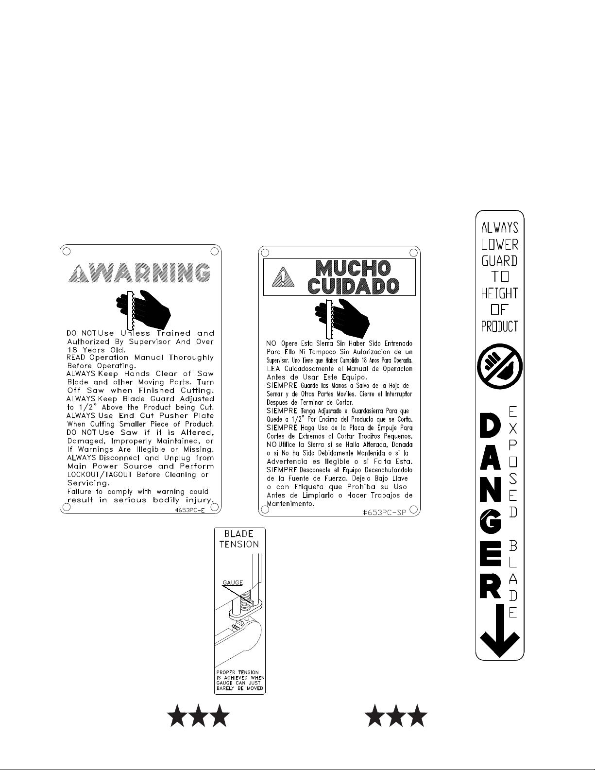
SHARP SAW BLADE. HANDLE WITH EXTREME CAUTION.
7. The stationary platter (Item No. A10163-1) is placed on top of the base structure and held in place by two
push-pull hold down rods (Item No. 10212W), located at the rear of the base.
8. The sliding meat carriage assembly (Item No. A10155) is installed by turning the movable stop assembly
(Item No. A200) clockwise. After the carriage assembly is in the channel for operation, turn the movable
stop counterclockwise to lock.
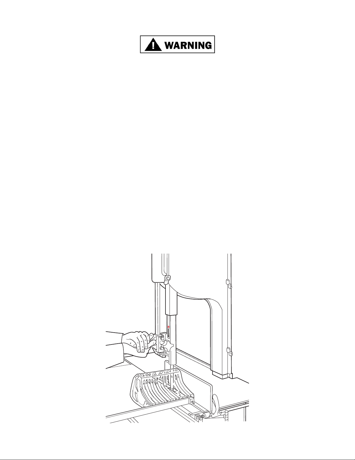
6. Placing blade on cutter: Hang upper wheel assembly (Item No. A10003U335) on the hinge bracket
(Item No. S71-0). Lift the nylon ller (Item No. 177). Hang blade on the upper wheel and hold with right
hand. With the left hand force the back of the blade between the front blade cleaners (Item No. 131), located
below the nylon ller. Lower the nylon ller and insert the back of the blade in the upper saw guide (Item
No. 602B). The blade has already dropped over the lower wheel. With right hand force the back of the
blade between the rear blade cleaners. The blade is now ready to be tightened. Press down on the ratchet
arm (Item No. 10-1) located at the rear of the base structure. Turn the upper wheel slowly by hand to ensure
proper tracking of the saw blade on the wheels. Tighten to proper tension. When the tension gauge (Item
No.197), located at the bottom rear of the head becomes tight laterally the blade is at proper tension.
9. Post SAFETY TIPS wall chart within easy view of operator. Keep Manual available to operator.
10. Machine MUST be properly grounded. Use qualied electrician to install according to building codes.
KEEP HANDS CLEAR OF SHARP MOVING BAND TYPE SAW BLADE

6
11. Make sure saw guide bar with saw guard is in its lowest position. Close head and base doors.
13. Watch for proper tracking of blade. Back of the blade should be centered in hole in saw guide in stationary
bar (Item No. S119A). Push the toggle switch to stop or press stop button to stop the machine.
15. Contact your local Distributor or BIRO directly if you have any questions or problems with the installation
or operation of this machine.
14. Check placement of all warning labels, wall chart and Manual. Machine is ready for trained operators to
process product.
WARNING LABELS
FOR BIRO POWER MEAT SAWS
Item No. 653PC-SPItem No. 653PC-E
Item No.
708
NOT TO SCALE
Item No. 710
12. Push the toggle switch to start or press start button and check for proper phasing of motor. Blade should be
traveling down through the saw guide.

7
OPERATION
SHARP MOVING BAND TYPE SAW BLADE
TO AVOID SERIOUS PERSONAL INJURY
ONLY Properly Trained Personnel Should Use This Equipment.
ALWAYS Keep Hands Clear of Band Type Saw Blade and Other Moving Parts.
NEVER Operate with Saw Guide Bar with Saw Guard in the Raised Position or the Saw Guard
Removed from the Saw Guide Bar.
ALWAYS Adjust the Saw Guide Bar with Saw Guard to Within ½” of Product to be Cut.
ALWAYS Use Safety End Cut Pusher Plate for Smaller Products or The Last Cuts of Product.
DO NOT Wear Gloves While Operating Machine.
ALWAYS Turn Off, Unplug from Power Source and Perform Lockout/Tag Out Procedures Before
Cleaning, Servicing or When Not in Use.
NEVER Leave Machine Unattended While the Saw is Running.
NEVER Operate Without All Warning Labels Properly Afxed to Machine and Wall Chart Posted.
A. TO PROCESS PRODUCT
1. Before starting power saw, adjust saw guide bar with saw guard to within ½”(13 mm) of product to be cut.
E
R
G
N
A
D
DO NOT Tamper With, Bypass, Alter or Modify this Equipment in Any Way From Its Original Condition.

8
2. Make sure all doors are closed and locked.
DO NOT WEAR GLOVES WHILE OPERATING
3. Adjust meat gauge plate forward to desired thickness of cut.
4. Push the toggle switch to start or press start button and watch blade for proper tracking.
5. Stand in front of the power saw, place product on the meat carriage. Pay attention to position of your
hands. Keep hands clear of moving band type saw blade. Leaning lightly against the scalloped front edge
of meat carriage, hold the product rmly in right hand with product face ush against the meat gauge plate.
Move the meat carriage from right to left at a steady rate until fully past the saw blade. Use left hand to
remove and stack cut product, NEVER REACH IN FRONT OF BAND TYPE SAW BLADE. On the
return stroke, pull the product slightly toward you to clear the blade.
NEVER REACH OR GRAB FOR PRODUCT IN FRONT OF
MOVING BAND TYPE SAW BLADE
6. ALWAYS use the Safety End Cut Pusher Plate (Item No. 256P) for smaller products or the last cuts of
product. The pusher plate is supplied as standard on all BIRO power saws.
7. When nished cutting, push the toggle switch to stop or press stop button.
Perform lockout/tagout procedure.
C
B
A

9
CLEANING
SHARP MOVING BAND TYPE SAW BLADE
TO AVOID SERIOUS PERSONAL INJURY
• ALWAYS Turn Off, Unplug From Power Source and Perform Lockout/Tagout Procedure to This Machine
BEFORE Cleaning or Servicing.
• ONLY Use Recommended Cleaning Equipment, Materials and Procedures.
• NEVER Spray Water or Other Liquid Substances Directly at Motor, Power Switch or any Other Electrical
Components.
• ALWAYS Thoroughly Clean Equipment at Least Daily.
CLEANING THE BIRO POWER SAW:
Disconnect electrical power to the machine before cleaning. Parts to be removed have been made accessible
and can be removed without tools. Notice in the drawing below that all parts are numbered. Each part should be
removed for cleaning in the numbered sequence shown. To ensure cleaner cuts, keep the parts on the cleaning
system in good condition. Parts on the cleaning system which should be checked weekly, and changed as
required are as follows: Wheel Cleaners (Part No. 179), Saw Cleaners (Part No. 131), Saw Guide in Stationary
Bar (Part No. S119A), Upper Saw Guide (Part No. 602B), Lower Blade Back-Up Guide (Part No. S604), and
Nylon Filler (Part No. 177).
4
1
8
5
9
10
26
7
11
3 Saw Blade

10
MAINTENANCE
SHARP MOVING BAND TYPE SAW BLADE
TO AVOID SERIOUS PERSONAL INJURY
• NEVER Touch This Machine Without Training and Authorization By Your Supervisor.
• ALWAYS Keep Hands Clear of Band Type Saw Blade and Other Moving Parts.
• NEVER Bypass, Alter, or Modify This Equipment in Any Way From Its Original Condition.
• PROMPTLY REPLACE Any Worn or Illegible Warning Labels.
• USE ONLY GENUINE BIRO Parts and Accessories Properly Installed.
A. GENERAL
1. Machine should be generally inspected every time it is cleaned (at least daily) to ensure that it is in good
condition and has not been damaged or tampered with.
a. SAW WHEELS: Clean outer diameter grooves daily. Check for cracks, gouges or wear on the ange
and grooves.
DO NOT IMMERSE UPPER WHEEL ASSEMBLY IN
WATER
b. WHEEL CLEANER ASSEMBLIES: Check condition of ber cleaner, change every four (4) weeks.
Check condition of tension spring, replace as needed.
c. REMOVABLE FINGER LIFT ASSEMBLY: Check condition of saw guard, make sure mounting
bolts are tight and the “DANGER EXPOSED BLADE” decal is afxed and legible. Check condition
of upper saw guide (Item No. 602B), replace every six (6) months. Check adjustment of upper saw
guide. Should be 1/32” between back of blade and saw guide carbide.
NEVER USE THIS MACHINE WITHOUT PROPERLY INSTALLED
AND FUNCTIONING SAW GUIDE BAR AND SAW GUARD
• ALWAYS Turn Off, Unplug From Power Source and Perform Lockout/Tagout Procedure to This
Machine BEFORE Cleaning or Servicing.
1. Remove the nger lift fastener knob and the nger lift assembly.
2. Remove the nger lift fastener stud.
3. Push the saw guide bar up and out of the top of the head structure.
4. Remove the saw guide bar spring.
5. Clean and lubricate the babbitt pocket area (the square indented area that seats the
saw guide bar spring).
6. Lower the new saw guide bar spring through the top of the babbitt pocket area
and guide the spring into position with a standard screwdriver. (NOTE: drawing)
7. While holding the saw guide bar spring in position, re-enter the saw guide bar
from the top compressing the saw guide bar spring slightly until the saw guide
bar slides past the spring.
8. Replace the nger lift fastener stud, the nger lift assembly and the nger lift
fastener knob.
9. Test by making several adjustments.
d. SAW GUIDE BAR: Check condition of bar for coating peeling and wear, replace as necessary. Check
saw guide bar spring for proper tension. The spring should hold the bar in any desired position in its
travel. Replace saw guide bar spring (Item No. 193) as necessary using the instructions below.

11
e. STATIONARY BAR ASSEMBLY: Check condition of nylon ller (Part No. 177), change every four (4) weeks.
Check condition of saw guide (Part No. S119A), check tracking of blade through guide, back of blade should be
centered in hole, replace every six (6) months. Check condition of lower blade back-up guide (Part No. S604).
Check adjustment of back-up guide, should have 1/32” gap between back of blade and saw guide carbide. Replace
every six (6) months.
f. SAW CLEANERS: Check condition of blade cleaners, replace every four (4) weeks.
i. MEAT GAUGE ASSEMBLY: Check free movement of meat gauge plate on gear rack. Gear rack to be kept
lubricated at all times with light food grade oil. Check operation of release handle. Check that worm gear engages
properly with gear rack. Check tension of release handle spring, replace as necessary.
j. MEAT CARRIAGE ASSEMBLY: Check for free movement through full range of travel. Check for side to side
tolerance, adjust as necessary. Check condition and grease bearings, replace as necessary. Check condition of
thumb guard, replace as necessary.
k. SAFETY ITEMS: Safety end cut pusher plate is with machine and accessible. All warning labels are present,
properly afxed and legible. Model and Serial Number plate properly afxed and legible. Wall poster within
operator’s view from machine. Manual accessible to operator.
g. RATCHET ASSEMBLY: Check for smooth operation through full range of travel. Check condition of
trigger spring, replace as necessary.
h. SLIDE GIBS: Check that head structure moves freely up and down. Check for side to side and fore to aft,
tolerance. Adjust as required. Grease every four (4) weeks.
7. MOTOR BEARINGS: Bearing grease will lose its lubricating ability over time, not suddenly. The
lubricating ability of a grease (over time) depends primarily on the type of grease, the size of the bearing,
the speed at which the bearing operates and the severity of the operating conditions. Good results can be
obtained if the following recommendations are used in your maintenance program.
A high grade ball or roller bearing grease should be used. Recommended grease for standard service
conditions is Polyrex EM (Exxon Mobil).
Equivalent and compatible greases include: Texaco Polystar, Rykon Premium #2, Pennzoil Pen 2 Lube,
and Chevron SRI.
Recommended lubrications intervals is every 12 months with the equivalent of two (2) teaspoons of grease.
If motor does not have zerk ttings, the motor bearings are sealed for life.
B. LUBRICATION: USE BIRO No. 374 GREASE FOR RE-GREASING
SEE INSTRUCTIONS BELOW
1. UPPER WHEEL BEARINGS: Grease
every four (4) months. Change grease every
twelve (12) months.
2. LOWER BEARING HOUSING: Grease
every four (4) months. Change grease every
twelve (12) months.
3. SLIDE GIBS: Grease every four (4) weeks.
4. MEAT CARRIAGE BEARINGS: Grease
every four (4) weeks.
5. SAW GUIDE BAR: Oil daily with food
machine oil.
6. MEAT GAUGE GEAR RACK: Oil daily
with food machine oil. When lubricating the upper wheel bearing it is important that the three hex head
screws securing the upper wheel hub cap be loosened slightly before attempting to
pump grease into the grease tting. Loosening the screws allows for an escape of
old broken down grease and air from the bearing cavity. Failure to loosen the screw
before greasing the upper bearings can cause the upper shaft seal to be dislodged
from the upper wheel allowing grease to escape and moisture to get into the cavity.
When nished greasing the bearings, retighten the three screws. Take care to also
clean off any grease that was forced out of the cavity during greasing.
-NOTE-
USE SHELL CASSIDA
GREASE EPS-2

12
248
S71-0
SEE #A116-13
SAW GUIDE
193
BAR AND FINGER
LIFT ASSEMBLY
WARNING
D
A
N
G
E
R
BIRO
11
NOTE:
ALWAYS REPORT MACHINE
SERIAL NO. WHEN
ORDERING PARTS 10006
S10335X
10005
10003U
A14U
A14L
A112
179
S229
S244
S295
S325
211Q
175
175-1-S
175-2-S
267
S262
S265
S270
272-7-1
S264-1
264G
271AL
S10272
10273
S242R
S249
HNNL25S
AS249R
10003
10217R
SEE MOTOR LIST
324
324A
HN20S
HHS065S
LW15S
FW10S
324
324A
HN25S
HHS080S
LW20S
FW08S
OR
10232
7PC
A200
TOGGLE SWITCH
SEE PAGE 20

13
WARNING
NSF
BIRO
MODEL
11
NOTE:
ALWAYS REPORT MACHINE
SERIAL NO. WHEN
ORDERING PARTS
10005
10301-2-B
653PC-E
AS10275
A260
10212W
212CP
SEE A196
SEE A19-1
NOT SHOWN:
LEFT SIDE: 10217PD
BASE PANEL DOOR
SEE A116-13
211MS
601
602B
12662-AL 10302HT
256P 10155
10120
A220
A10163-1
A415D
10251AL
SEE V-BELTS
221-XX
SEE MOTOR PULLEYS
4-XXAL
239C31
239C30
FROM S/N: 7405-7554
HN20S
LW20S
HHS055S
239-B32-AR
239-B31-2
(NOT SHOWN)
AS239-B30-B
S239-B30-B
WARNING
NSF
BIRO
MODEL
11
WARNING
NSF
BIRO
MODEL
11

14
A10005 HEAD & DOOR ASSEMBLY
BIRO
11
HHS050S (3)
LW15S (3)
S71-0
SSS15S
10308
375 (2) 10005
112
310
10006
143
HHS010S
340
S325
A71
UPPER WHEEL
HINGE BRACKET
ASSEMBLY
A112
HEAD DOOR HANDLE
ASSEMBLY
14-0-U
A14U
HEAD DOOR HINGE
ASSEMBLY - UPPER
14-0-L
A14L
HEAD DOOR HINGE
ASSEMBLY - LOWER
HHS025S (2)
LW10S (2)
LW10S (2)
HHS035S (2)
LW10S (2)
HHS035S (2)
HHS025S (2)
LW10S (2)
14GP-1
14GP
14-0
14-0
SSS15S Set screw, 5/16 -18 x 5/16 cup point, SS
14GP Head door hinge pin, long, 1½”
14GP-1 Head door hinge pin, short, 1¼”
310 Waved washer
Item No. Description
A10006 Head door assembly
HHS050S Hex head screw, 5/16 -18 x ⅝, SS
A116-13 Saw guide bar assembly
A10005 Head & door assembly
LW15S Lock washer, 5/16 , SS
A112 Head door handle assembly
A14L Head door hinge assembly - lower
A71 Upper wheel hinge bracket assembly
A14U Head door hinge assembly - upper
HHS025S Hex head screw, ¼-20 x ½, SS
HHS035S Hex head screw, ¼-20 x ⅝, SS
A196 Tension spring assembly
143 Head door catch
10006 Head door (use A10006)
10005 Head
340 Star lock washer
112 Head door latch
S71-0 Upper wheel hinge bracket
LW10S Lock washer, ¼, SS
HHS010S Hex head screw, 10-32 x ⅜, SS
S325 Wheel cleaner washer, SS
10308 Babbit pocket shield
14-0 Head door hinge, (not sold separately)
14-0-L Head door hinge w/ short pin, lower
14-0-U Head door hinge w/ long pin, upper
375 Drive screws
NOT SHOWN
Item No. Description

15
A10003U335 (SERIAL NUMBER 7705 ON)
UPPER WHEEL ASSEMBLY WITH HINGE PLATE
A295
WHEEL CLEANER ASSEMBLY
UPPER WHEEL HINGE PLATE ASSEMBLY
A10335X
UPPER WHEEL ASSEMBLY W/O HINGE PLATE
A10003U (SERIAL NUMBER 7705 ON)
UPPER SHAFT BEARING
A247-1
230DL
S10335X
S252X 247
S253
HN35S
ASSEMBLY W/O WHEEL
A227
A227
530 530
10003U 237
238
234 HHS010S
513
248
179 HHS004S
HN05S
S295
S325 S244
S229
CAD NO. A10003U335
S229 Wheel cleaner arm torsion spring, SS
S244 Wheel cleaner arm stud, SS
S253 Upper wheel aligning screw, SS
S295 Wheel cleaner arm, SS
S325 Wheel cleaner washer, SS
10003U Upper wheel, 10”
179 Wheel cleaner
230DL
234
Upper shaft seal, double lip
Grease tting, upper wheel
237 Upper shaft castellated lock nut
238 Upper shaft castellated lock nut washer
247 Upper shaft
248 Upper wheel hub cap
S252X Shaft lock nut, SS
513 Upper wheel hub gasket
Retaining ring, (2 req.)
530
HHS004S Hex head screw, 8-32 x ⅜, SS
HHS010S Hex head screw, 10-32 x ⅜, SS
HN05S Hex nut, 8-32, SS
HN35S Hex nut, ⅜-16, SS
S10335X Upper wheel hinge plate, SS
Description
Item No.
A10003U335 Upper wheel assembly with hinge plate
A10003U Upper wheel assembly without hinge plate
A247-1 Upper shaft bearing assembly, less spacer
A10335X
A227 Bearing cup/cone assembly
A295 Wheel cleaner assembly
Upper wheel hinge plate assembly
DescriptionItem No.
A360 Lower bearing housing assembly w/o wheel
A363 Lower bearing cup/cone assembly
HN25 Hex nut, ⅜ -16
LW20S Lock washer, ⅜, SS
SSS05S Set screw, 10-24 x ⅜, SS, cup point
231DL Lower shaft seal, double lip
10003 Lower saw wheel, 10”
277 Lower shaft pulley key
S360CB-1 Carriage bolt, ⅜ -16 x 1¼, SS
A361 Lower shaft and bearing assembly
SSS20 Set screw, ⅜ -16 x ⅜, knurled cup point
DescriptionItem No.
300 Lower shaft woodruff key
303 Lower shaft nut
360 Lower bearing housing
360A1 Lower bearing housing grease tting
360B-1 Set screw ½-13 x ½
361 Lower shaft
362 Lower bearing housing adjusting cap
10251AL Upper V-belt pulley, 7.8 x 1”
LOWER BEARING HOUSING ASSEMBLY,
10251AL
231DL
10003
WITHOUT WHEEL
A360
277
361
300
303
362
360A1
SSS05S
360
360B-1
HN25 LW20S S360CB-1
362
231DL
A363
A363
SSS20
A361
SSS05S

16
A19-1 Ratchet assembly
HN35S Hex nut, ⅜-16 SS
FW07S Flat washer, ⅜ SS
LW10S Lock washer, ¼ SS
HN15S Hex nut, ¼-20 SS
HHS025S Hex head screw, ¼-20 x ½ SS
S11 Ratchet trigger SS
19CB Carriage bolt ¼-20 SS
S189 Ratchet arm stud SS
S240 Ratchet trigger spring
10-1 Ratchet arm
S19 Ratchet base SS
Item No. Description Item No. Description
Item No. Description
A10273-S275 Meat gauge assembly
HHS049NL Hex screw- nylon, 5/16-18 x ½
AS10275 Meat gauge plate assembly w/ release
HN20S Hex nut, 5/16-18 SS
FW10S Flat washer, 5/16 SS
A262 Meat gauge release assembly
Item No.
264G Meat gauge hand wheel groove pin
S264-1 Meat gauge hand wheel, SS
14275 Meat gauge arm
S10275 Meat gauge plate only, SS
LW10S Lock washer, ¼ SS
S235 Taper pin, 4 x ¾ SS
LW15S Lock washer, 5/16 SS
S262 Meat gauge release handle, SS
HHS040S Hex head screw, ¼-20 x ¾ SS
272-8 Cap nut, 5/16-18, SS
267 Meat gauge release cotter pin
272-7-1 Lock knob, 5/16-18, 3 point
271AL Meat gauge worm gear, Aluminum
S270 Meat gauge release pin, SS
S265 Meat gauge release spring, SS
S10272 Meat gauge gear rack, SS 272-12 Brass ball
AS10275-5 Meat gauge plate assembly less release
Description
10273 Meat gauge bracket (not sold separately)
HHS060S Hex head screw, 5/16-18 x 1 SS
272-13 Hex bolt, 5/16-18 x 1¼, w/ cotter hole
272-14 Castle nut, 5/16-18, SS

17
Hex head screw, 8-32 x ½, SS
Cleaning unit assembly w/ S604
Hex head screw, 10-24 x ⅜, SS
Hex head screw, 8-32 x ¼, SS
Wheel cleaner assembly
Lower blade back-up w/ carbide
Wheel cleaner arm stud, SS
Wheel cleaner arm stud washer, SS
Wheel cleaner arm, SS
Cleaning unit casting
Hex nut, 8-32 SS
Wheel cleaner arm spring, SS
Wheel cleaner
HHS005S
A290CT
HHS010S
HHS003S
A295
S604
S244
131
S325
S295
290CT
HN05S
S229
291-1
179
AS130 Saw cleaner assembly, SS
Blade cleaner, SS
Cleaning unit fastener knob
Item No. Description
HHS015S Hex head screw, 10-32 x ⅞, SS
HHS020S Hex head screw, ¼-20 x ⅜, SS
FW06S Flat washer, ¼ SS
A602 Saw guide assembly, upper
299 Saw guide bar stop, short
17211-35 Finger lift shim, .035
116-13 Saw guide bar, 13”
12662-AL Saw guard for aluminum head
17211-22 Finger lift shim, .022
HHS065S Hex head screw, ⅜-16 x 1½, SS
RHS10S Round head screw, 10-32 x ¾ SS
HN10S Hex nut, 10-32 SS
RHS25S Round head screw, ¼-20 x ¾ SS
LW10S Lock washer, ¼ SS
LW05S Lock washer, #10 SS
211MS Finger lift bracket
602BFSC Upper saw guide, narrow, sh
211Q Fastener knob, 4 point
708 Decal “DANGER EXPOSED BLADE”
602B Upper saw guide with carbide
601 Upper saw guide bracket
A116-13 Saw guide bar assembly 13” AL head
A211MS-AL Finger lift assembly, removable AL head
193 Saw guide bar spring
A603604 Lower blade backup guide assembly
603
HHS010S
290CT
SSS13
315
291-1
603-1
S604
A603604
LOWER BLADE
BACK-UP GUIDE
ASSEMBLY
A290CT
CLEANING UNIT
TOTAL ASSEMBLY
A295
WHEEL
CLEANER
ASSEMBLY
179
HHS005S
HN05S
S295
S325
S244
S325 S229
HHS003S HHS003S
131131
S130
AS130
SAW CLEANER
ASSEMBLY
Set screw cup point, ¼-20 x ⅜
SSS13
S130 Saw cleaner bracket, rear, SS
Pan head screw adjusting guide
Lower guide bracket
315
603-1
603
Lower guide bracket stud
A290CT
CLEANING UNIT ASSEMBLY
A116-13
SAW GUIDE BAR ASSEMBLY

18
AS415D
STATIONARY BAR
ASSEMBLY, SS
Description
AS415D
LW10S
S119A
177
S415D
S268
HHS025S Hex head screw, ¼-20 x ½ SS
Stationary bar assembly, SS
Stationary bar headless screw
Lock washer, ¼ SS
Saw guide in stationary bar, SS
Nylon ller
Stationary bar, SS
Item No.
Description
A196
LW10S
S118
196
197
111AL
HHS040S Hex head screw, ¼-20 x ¾SS
Tension spring assembly
Tension spring pin, Aluminum
Lock washer, ¼ SS
Tension spring plate
Saw tension spring
Tension spring gauge
Item No.
198 Cap, for tension pin
A196 TENSION SPRING ASSEMBLY
Other manuals for 11
1
Table of contents
Other BIRO Saw manuals
Popular Saw manuals by other brands

Hitachi
Hitachi C 10RE Instruction manual and safety instructions

Hitachi Koki
Hitachi Koki C 6SS Handling instructions

GreenWorks Tools
GreenWorks Tools 3600107a user manual

Makita
Makita LC1230 instruction manual

Dr.Schulze
Dr.Schulze FS-500 B Original operating instructions

Lissmac
Lissmac DTS 420 PE/N operating manual