Bison HHBD01SK-01 User manual

1
THIS OPERATOR’S MANUAL IS EFFECTIVE
FOR THE FOLLOWING MODELS:
1 – 5 TON CAPACITY
3 – PHASE 230V/ 460V
SINGLE & DUAL SPEED MODELS
ELECTRIC CHAIN HOIST USER MANUAL

2
TABLE OF CONTENTS
HOIST SPECIFICATIONS
• Single Speed Hoist ............................................................................... Page 3
• Single Speed Hoist + Trolley .............................................................. Page 4
• Dual Speed Hoist .................................................................................. Page 5
• Dual Speed Hoist + Trolley .................................................................. Page 6
HOIST INSTALLATION
• Pre-installation ...................................................................................... Page 7
• Voltage Adjustment .............................................................................. Page 7
• Installation Instructions ....................................................................... Page 9
TROLLEY INSTALLATION
• Pre-installation ...................................................................................... Page 10
• Voltage Adjustment .............................................................................. Page 11
• Installation Instructions ....................................................................... Page 12
• Direction Adjustment ............................................................................ Page 13
OPERATION
• Controls ................................................................................................. Page 16
• Advisory ................................................................................................. Page 16
MAINTENANCE
• Inspection Periods ................................................................................ Page 17
• Hoist Brake ............................................................................................ Page 18
• Load Chain ............................................................................................ Page 19
• Trolley Brake ......................................................................................... Page 20
• Contactor Inspection ............................................................................ Page 20
• Hook Inspection .................................................................................... Page 21
DIAGRAMS
• Hoist Housing Assembly ...................................................................... Page 23
• Hoist Gear Assembly ............................................................................ Page 25
• Hoist Chain Reeving & Attachments ................................................... Page 27
• Hoist Chain Entry & Limit Switch Assembly ...................................... Page 29
• Motorized Trolley Assembly ................................................................ Page 31
ELECTRICAL DIAGRAMS
• 1 Ton - 5 Ton Single Speed Hoist Wiring ............................................ Page 35
• 1 Ton Dual Speed Hoist Wiring ............................................................ Page 36
• 2 Ton – 5 Ton Dual Speed Hoist Wiring .............................................. Page 37
• 1 Ton – 5 Ton Single Speed Hoist + Trolley Wiring ........................... Page 38
• 1 Ton – 5 Ton Dual Speed Hoist + Trolley Wiring .............................. Page 39

3
TECHNICAL SPECIFICATIONS
SINGLE SPEED HOIST
Product Code
Capacity
Headroom (C)
A
B
D
E
K
L
N
tons
inches
inches
inches
inches
inches
inches
inches
inches
HHBD01SK-01
1
19.69
23.43
12.60
10.75
7.25
1.57
1.22
0.94
HHBD02SK-01
2
23.62
25.39
12.99
14.00
9.50
1.93
1.37
1.18
HHBD03SK-01
3
29.53
30.91
15.55
17.00
11.50
2.32
1.65
1.38
HHBD05SK-02
5
38.58
30.91
15.55
17.00
11.50
2.36
1.65
1.69
Product Code
Capacity
Standard
Lift
Height
Push Button Cord
Lifting Speed
Motor Output
Control
Voltage
Lifting Motor
Rated
Current (amps)
Load Chain
Size Ø
Chain
Fall
Lines
Net Weight
tons
feet
feet
ft/min
hp
Volts
@230v
@460v
mm
Lbs.
HHBD01SK-01
1
20
17
23.6
2.01
110
6
4.5
Ø 8 x 24
1
125.7
HHBD02SK-01
2
20
17
14.4
2.01
110
6
4.5
Ø 10 x 30
1
188
HHBD03SK-01
3
20
17
17.7
4.02
110
11
8
Ø 11.2 x 34
1
298
HHBD05SK-02
5
20
17
9.2
4.02
110
11
8
Ø 11.2 x 34
2
364

4
TECHNICAL SPECIFICATIONS
SINGLE SPEED HOIST + TROLLEY
Product Code
Capacity
Headroom (C)
A
B
D
K
L
E
N
O
P
R
T
tons
inches
inches
inches
inches
inches
inches
inches
inches
inches
inches
inches
inches
HHBD01SK-01
+WPC01
1
18.1
23.43
12.6
12.25
1.65
1.22
4.87
0.94
4.37
8.11
5.59
9.09
HHBD02SK-01
+WPC02
2
22
25.39
12.99
12.75
1.93
1.37
4.75
1.18
5.00
9.33
5.59
9.09
HHBD03SK-01
+WPC03
3
28
30.91
15.55
13.5
2.32
1.65
5.5
1.38
5.51
10.43
5.59
9.09
HHBD05SK-02
+WPC05
5
37
30.91
15.55
15.5
2.36
1.65
5.5
1.69
6.14
11.65
5.59
9.09
Product Code
Capacity
Standard
Lift
Height
Push
Button
Cord
Lifting
Speed
Motor
Output
Motor Rated
Current (amps)
Load
Chain Size
Ø
Chain
Fall
Lines
Trolley Speed
Trolley
Output
Trolley
Flange
Width
Net Weight
tons
feet
feet
ft/min
hp
@230v
@460v
mm
ft/min
hp
inches
lbs.
HHBD01SK-01
+WPC01
1
20
17
23.6
2
6
4.5
Ø 8 x 24
1
48
0.5
3.15-12.00
213.8
HHBD02SK-01
+WPC02
2
20
17
14.4
2
6
4.5
Ø 10 x 30
1
48
0.5
3.23-12.00
277.8
HHBD03SK-01
+WPC03
3
20
17
17.7
4
11
8
Ø 11.2 x 34
1
48
0.5
3.94-12.00
434.3
HHBD05SK-02
+WPC05
5
20
17
9.2
4
11
8
Ø 11.2 x 34
2
48
1
4.33-12.00
560

5
TECHNICAL SPECIFICATIONS
DUAL SPEED HOIST
Product Code
Capacity
Standard
Lift Height
Push
Button
Cord
Lifting
Speed
Motor
Output
Control
Voltage
Lifting Motor Rated
Current (amps)
Load Chain
Size Ø
Chain
Fall
Lines
Net Weight
tons
feet
feet
ft/min
hp
Volts
@230v
@460v
mm
lbs.
HHBDSK01-01D
1
20
17
23.6 / 7.9
2.01
110
9/3.8
7/2.4
Ø 8 x 24
1
147.70
HHBDSK02-01D
2
20
17
14.4 / 4.6
2.01
110
7/4
4.5/2.6
Ø 10 x 30
1
196.20
HHBDSK03-01D
3
20
17
24 / 4.8
4.02
110
8.5/12
6.5/8.5
Ø 11.2 x 34
1
330.70
HHBDSK05-02D
5
20
17
7.2 / 2.3
4.02
110
8.5/12
6.5/8.5
Ø 11.2 x 34
2
412.30
Product Code
Capacity
Headroom (C)
A
B
D
E
K
L
N
tons
inches
inches
inches
inches
inches
inches
inches
inches
HHBDSK01-01D
1
20.15
23.54
12.6
11.81
8.31
1.57
1.26
0.94
HHBDSK02-01D
2
22.50
25.51
12.99
12.60
8.10
1.93
1.57
1.18
HHBDSK03-01D
3
30.95
31.02
15.55
18.31
12.75
2.32
1.77
1.38
HHBDSK05-02D
5
40.50
31.02
15.55
18.31
12.75
2.36
1.77
1.69

6
TECHNICAL SPECIFICATIONS
DUAL SPEED HOIST + TROLLEY
Product Code
Capacity
Standard
Lift
Height
Push
Button
Cord
Lifting
Speed
Motor
Output
Control
Voltage
Lifting Motor Rated
Current (amps)
Load
Chain Size
Ø
Chain
Fall
Lines
Trolley
Speed
Trolley
Output
Trolley
Flange
Width
Net Weight
tons
feet
feet
ft/min
hp
Volts
@230v
@460v
mm
ft/min
hp
inches
lbs.
HHBDSK01-01D
+WPC01D
1
20
17
23.6 / 7.9
2.01
110
9/3.8
7/2.4
Ø 8 x 24
1
90 / 32
0.5
3.15-12.00
257.9
HHBDSK02-01D
+WPC02D
2
20
17
14.4 / 4.6
2.01
110
7/4
4.5/2.6
Ø 10 x 30
1
80 / 28
0.5
3.23-12.00
321.9
HHBDSK03-01D
+WPC03D
3
20
17
24 / 4.8
4.02
110
8.5/12
6.5/8.5
Ø 11.2 x 34
1
64 / 24
0.5
3.94-12.00
478.4
HHBDSK05-02D
+WPC05D
5
20
17
7.2 / 2.3
4.02
110
8.5/12
6.5/8.5
Ø 11.2 x 34
2
60 / 21
1
4.33-12.00
615.1
Product Code
Capacity
Headroom
(C)
A
B
D
E
K
L
N
O
P
R
T
tons
inches
inches
inches
inches
inches
inches
inches
inches
inches
inches
inches
inches
HHBDSK01-01D +WPC01D
1
18.11
23.54
12.6
12.25
4.75
1.65
1.26
0.94
4.37
8.11
5.59
9.09
HHBDSK02-01D +WPC02D
2
22.05
25.51
12.99
12.75
4.75
1.93
1.57
1.18
5
9.33
5.59
9.09
HHBDSK03-01D +WPC03D
3
27.95
31.02
15.55
13.5
5.5
2.32
1.77
1.38
5.51
10.43
5.59
9.09
HHBDSK05-02D +WPC05D
5
37.01
31.02
15.55
15.5
5.5
2.36
1.77
1.69
6.14
11.65
5.59
9.09

7
HOIST INSTALLATION
PRE-INSTALLATION INSPECTION
1. Remove your hoist from the crate.
2. Take note of the preset voltage that your hoist has been set to. This information
can be found on the lid of the shipping crate. If you are not sure of your hoist
voltage, contact Bison’s customer service.
3. Give the hoist a visual inspection. Look for any obvious defects or damage to the
unit.
4. Always make sure your power supply is disconnected before you wire your hoist.
5. If necessary, make the changes to your hoists voltage by following the steps
below.
HOIST DUAL VOLTAGE ADJUSTMENT
All hoists come with the option of using either 460v or 230v power supply. The default
voltage on all hoists is prewired for 460v. (unless otherwise stated)
This can be adjusted as follows:
1. Transformer Connection: The transformer like the hoist is wired as standard from
the factory for an incoming power supply of 460v.The Red wire (0V) of the
transformer is connected to T2 of the reversing contactor. The Blue wire (460V)
is connected to T3 of the same reversing contactor.
If the incoming power supply is changed to 230v then the Yellow wire of the
transformer (230V) should be connected to T3 of the reversing contactor. The
Blue wire (460V) must be disconnected from T3 and well insulated. Ensure the
cable is insulated in a manner that will not allow it to float around in the panel.
2. Motor Connection:
Single Speed: The Hoist motor is wired as standard from the factory for an
incoming power supply of 460v. There are 6 wires from the motor Labelled U1;
V1; W1; W2; U2; V2. The standard 460v connection is W2/U2/V2 are joined
together and U1/V1/W1 are connected to T1/T2/T3 of the reversing contactor.
For 230v main incoming supply voltage then a parallel connection of the wires is
required as follows: W2&U1 connect to T1-U2&V1 connect to T2-V2&W1
connect to T3.

8
Dual Speed: For Dual speed 230V connection look for the 2 sets of 3 cables that come
from the motor stator that have a cable nut or crimp connecting them together. They are
normally tucked behind the contactor backing plate to the left of the hoist panel. 1 set
will be red wires and the other set will be black wires. The red wires will be for slow and
the black wires will be for fast.
Connect each set as you would a single speed motor as explained above, make sure
you connect the red wires to the red wires on the bottom of the slow contactor terminals
T1-T2-T3 and the same with the black wires onto the fast contactor terminals T1-T2-T3

9
HOIST INSTALLATION
1. The hoist comes already filled with oil. No oil needs to be added inside the hoist
during installation.
2. Be sure that the hoist is mounted to or from a structure that can support the hoist
and its rated load.
3. Using the power cord, either connect the hoist to your plug or a junction box.
4. To start the hoist, release the red emergency stop button on the controller by
twisting the red knob clockwise till it pops out and then press the start or on
button (if applicable).
5. Once the emergency stop button has been released and the start/ on button has
been pressed you should instantly hear a click in the hoist as the main contactor
comes in. You can now test the hoist directions.
6. If you have wired your hoist to the power supply and the hoist is not functioning it
may be because your phases are reversed. This can be checked by opening the
front cover of the hoist. There you will find a small white relay with led lights on it.
If the fault light is on you must swop any 2 of the 3 power cables at your plug or
junction box.
7. Before proceeding to operate the hoist, check that the hoist directions are
correct, that the emergency stop button works and that the limit switches work.
8. Apply the oil provided to the chain for easier operation and to prolong the
lifespan.
9. To attach the chain bag/ container run the hoist until the hook is fully extended
(DOWN) and then fasten the bag/ container to the hoist. Once the bag is
securely fastened feed the slack chain (non-load bearing) into the bag/ container.
Then run the hoist in the reverse motion (UP), guiding the slack chain into the
bag/ container (only applicable for those models supplied with the bag/
container).
FASHING FAULT
LIGHT = PHASES
ARE REVERSED

10
PRE-INSTALLATION INSPECTION
1. Remove your hoist and the trolley from the crate.
2. If necessary, make the changes to your hoist’s voltage. (Refer to page 7.)
remember any voltage changes that are made in the hoist must be made in the
trolley’s motor panel. (The transformer in the hoist operates the hoist & the
trolley)
Trolley Dual Voltage Adjustment:
When opening the trolley’s crate, you will find that the trolley motor is not connected yet
to the panel that houses the trolley contactors. This is done for transportation and site
fitment purposes allowing the trolley to be separated completely during installation
without the cable hindering the installation onto the beam.
460v = Star Connection
230v = Delta Connection
Single Speed
On a single speed 460v Trolley you will have a short black cable from the trolley
enclosure with 3 wires marked U1/V1/W1, these will go into the gland on the trolley
motor and be connected to the corresponding U2/V2/W2 on the motor terminal strip.
If the main incoming voltage is 230v then the trolley needs to be reconfigured to a delta
connection as per the below chart.

11
HOIST + MOTORIZED TROLLEY ASSEMBLY & INSTALLATION

12
TROLLEY INSTALLATION
1. Be sure that your beam and its structure can support the weight of the hoist and
its rated load.
2. The trolley comes packaged already assembled. To attach the hoist, you will
need to remove the lock pin from the end of the shaft and any external spacers.
Remove the electrical plate and any spacers.
3. To fit the trolley to the beam you will need to calculate the correct number of
spacers on both sides of the coupling so that the center of the coupling is in line
with the web of the beam. Take the measurement of your beam flange.
4. You will need to lay out the trolley to measure the number of spacers you will
need. Connect the 2 trolley plates together by inserting the shaft into the plates.
Take note of the guide rollers on each plate. These guide rollers are where the
internal measurement will be taken. Spread the plates the same distance apart
as the width of the beam’s flange. Now you can measure how many spacers you
will need on the shaft- either side of the coupling. Make sure to leave 1/8-inch
space on both sides of the coupling. (Refer to the diagrams below)
(Flange width – thickness of coupling + ¼ inch = total length of spacers)
All 4 guide rollers must roll along the edge of the beam flange. The ¼-inch space
that was left is to allow the trolley to roll without getting caught while moving.

13
5. Once you have worked out the number of spacers you will need, any left-over
spacers must be packed on the exposed outside end of shaft. Once you are
ready to mount the trolley.
6. To mount the trolley to the beam you must couple the motor end of the trolley
with your correct number of spacers onto the hoist, followed by the rest of the
spacers and the electrical plate.
7. The trolley which is now mounted to the hoist must be kept spread wide
enough to fit the wheels inside the beam.
8. Once the wheels are inside the beam you can push the trolley together.
9. Fit the left-over spacers on the outside of the exposed beam tight enough for
the lock pin to hold the spacers in place.
10. Make sure to secure the Lock pin with the spilt pin.
11. After the trolley has been mounted to the beam, the trolley motor must be
connected. There is a short cable from the electrical panel of the trolley which
provides power to the trolley motor.
TROLLEY MOTOR
WIRED FOR 460V
TROLLEY MOTOR CORD
(U1, V1, W1) & (U2, V2, W2)

14
12. Plug in and fasten the trolley plugs into the hoist.
13. The hoist is now ready to test. Connect the power cord to the mains.
14. Once the emergency stop has been released and the start/ on button has
been pressed you should instantly hear a click in the hoist as the main
contactor comes in. You can now test the hoist and trolley directions. Before
proceeding to operate the hoist, check that the hoist directions are correct,
that the emergency stop button works and that the limit switches work.
15. If you have wired your hoist to the power supply and are not getting any
power to the hoist you might have reversed 2 of the phases. This can be
checked by opening the front cover of the hoist. There you will find a small
white relay with led lights on it. If the fault light is on you must swop any 2 of
the 3 power cables. (Refer to page X)
16. If your trolley’s directions are not correct, wiring changes in the trolley will
need to made.
TROLLEY DIRECTION CHANGE
If after having wired the trolley in and you find that directions are wrong this can easily
be rectified by following these steps.
Single speed: If when you push the cross travel direction the hoist/trolley moves in a
particular direction and you want it to move in the opposite direction when you push the
same button open up the trolley motor and swop positions of 2 of the wires of the cable
you previously installed such as u1 with v1, this is known as phase reversal, now when
you push the cross travel directional button the trolley will move in the opposite
direction.
Dual Speed: After completing the wiring and when testing for the first time be very
careful when operating the trolley. Conduct a small momentary test by pushing the slow
button in any direction and testing if slow is the first speed, if the trolley moves quickly
you may have wired it incorrectly, go back and check wiring in the motor.

15
DUAL SPEED DIRECTION CHANGE
Once wiring is correct and when you push slow the hoist moves in each direction slowly
then momentarily test the fast, if the hoist continues moving in the same direction in fast
as it did in slow then you have completed the trolley wiring successfully, however if the
fast speed suddenly changes the direction that the hoist was travelling when in slow you
need to go the trolley terminal strip and swop 2 phases on (U2)Locate the electrical panel
of the trolley motor.
1. Remove the cover.
2. Inside you will find 3 black cables, crimped together and 3 red cables crimped together.
These must be left crimped together if the host and trolley are running on 460v.
3. There are 6 cables already connected to the terminal strip from trolley’s motor. A set of 3
red cables and a set of 3 black cables.
4. Feed the short cable coming from the trolley’s contactor control box into the motor panel
following the diagram above.
5. You can now power up the trolley and test the directions.
NOTE:
Depending on the factory’s order of the trolley motor wiring, you might find your fast and
slow speed’s directions are swoped. This can be simply corrected by changing 2 cables.
Example: take V1 and W1 and swop them around.
TROLLEY MOTOR
CORD
RED
(SLOW SPEED)
BLACK
(FAST SPEED)
U2
V2
W2
U1
W1
V1
U1
W1
V1
SWOP
THESE 2
CABLES

16
OPERATION
Hoisting:
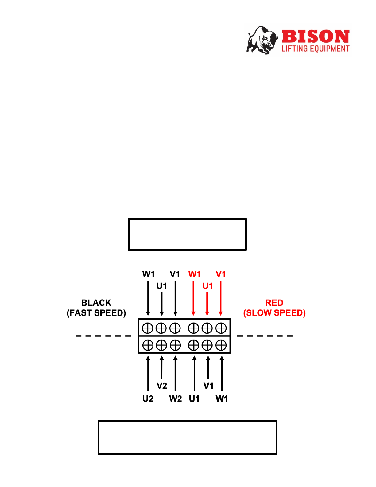
Dual speed models are controlled by pushing the pendent buttons down in 2 stages of
depression. Single depression engages a slow speed. Full depression engages the fast
speed.
Install the hoist to a support structure. It is the user/ owner’s responsibility to ensure the
chosen support structure has the sufficient strength to support the hoist and the rated
working load.
Do not attempt to lengthen the load chain in any way. Do not attempt to repair the
hooks.
General:
1. The friction-clutch is designed to allow the first reduction gear to slip on an
excessive overload. An overload is indicated when the hoist will not raise the
load. Also, some clutching noise may be heard if the hoist is loaded beyond rated
capacity. Should this occur, immediately release the raising control to stop
operation of the hoist. At this point, the load should be reduced to the rated hoist
capacity. When the excessive load is removed, normal hoist operation is
automatically restored. [CAUTION: the friction clutch is susceptible to
overheating and wear when slipped for extended periods. Under no circumstance
should the friction clutch be allowed to slip for more than a few seconds.]
2. Before picking up a load, check to see that the hoist is directly overhead. Avoid
off-center loading of any kind.
3. Take up as lack load chain carefully and start hoisting load gently to avoid shock
and jerking of the load chain. If there is any evidence of overloading, immediately
lower the load and remove the excess load.
4. Do not allow the load to swing or twist while hoisting.
5. Do not allow the load to be against the hook latch or the tip of the hook.
6. Make sure the pendant cord is straight and is not tangled in the chain. Be careful
not to snag the cord on any sharp edges or objects.
7. When handling material that is being immersed in water, baths or any liquid, use
a chain sling to prevent the hook block from having to be submerged- this will
stop any liquid from penetrating the bearing.
Precautions
• During overhead lifting operations, personnel should NOT stand beneath the
suspended load.
• Prevent the load chain from dragging over sharp edges or corners.
• Be cautious of having fingers caught in the mechanisms.
• Do NOT attempt to lift people.
• Do NOT use the load chain to basket or choke a load.
• Do NOT drag or drop the hoist.
• Do NOT put the bottom hook through the loop of the chain. (only applicable on 2-
fall models)

17
MAINTENANCE:
The inspection procedure advised is based on ANSI/ASME
B30.16. The following definitions are from ANSI/ASME B30.16.
INSPECTION CLASSIFIACTION
The inspection procedure is divided into two general grades based upon the intervals at
which inspection should be performed.
HOIST SERVICE DUTY
DUTY
Average % of rated capacity
NORMAL
0 to 33%
HEAVY
33 to 67%
SERVERE
67% TO 100%
SPECIAL
SPECIAL CONDITIONS
Frequent: Operators are to make visual inspections as often as required.
• Normal Duty Service – monthly
• Heavy Duty Service – weekly to monthly
• Severe Duty Service – daily to weekly
• Special Duty Service – recommend being inspected by a qualified
individual before and after each operation.
Periodic: Qualified individuals are to make visual inspections as often as required.
• Normal Duty Service – annually
• Heavy Duty Service – semiannually (twice a year)
• Severe Duty Service – quarterly
• Special Duty Service – recommend being inspected by a qualified
individual before and after each operation.
FREQUENT INSPECTION
The following is required to be inspected frequently:
• All functional operating mechanisms.
• Functionality of limit switch
• Hoist braking system
• Hooks in accordance with ANSI/ASME B30.10
• Hook latches
• Load chain
• Load chain reeving

18
Periodic Inspection
The following is required to be inspected periodically:
ANSI/ASME B30.16 requires all hoists subject to disassembly of load suspension parts,
to undergo a load test after re-assembly to pass full inspection.
Requirements of frequent inspection:
• Evidence of loose bolts, nuts, or rivets.
• Evidence of wear, corrosion, cracks, or distortion to parts such as load blocks,
suspension housing, chain attachments, clevises, coupling, suspension bolts,
shafts, gears, bearings, pins and rollers.
• Evidence of damage to bottom block assembly.
• Evidence of excessive wear on motor or load brake.
• Evidence of damage of supporting structure/ trolley.
• Direction labels on pendant control stations.
• Warning labels properly attached to the hoist.
• Load chain end connections.
• Evidence of wear, cracks or stretching on the load chain.

19
LOAD BRAKE ADJUSTMENT
Brake device should be checked and cleaned of all dust and oil every three months.
The air gap of the brake is as standard 0.078 inches. The gap should be measured
between the brake drum and pull rotor. The gap adjustment is done by turning the
adjustment nut (refer to diagram above). Using a feeler gauge, measure the gap. Adjust
until set. If the gap will not set, disassemble the motor brake and inspect all motor brake
parts and the order. If necessary, replace the brake drum or motor cover.
If the electric chain hoist is mounted to an electric trolley, it is important to inspect both
brakes- Trolley and Hoist.
BRAKE DRUM LINING (SINGLE SPEED)
HOIST CAPACITIES
DEFAULT
REPLACE
INCHES
INCHES
1 TON
0.31
0.23
2 TON
0.31
0.23
3 TON
0.31
0.23
5 TON
0.31
0.23
BRAKE DRUM LINING (DUAL SPEED)
HOIST CAPACITIES
DEFAULT
REPLACE
INCHES
INCHES
1 TON
0.28
0.20
2 TON
0.28
0.20
3 TON
0.28
0.20
5 TON
0.28
0.20

20
CHAIN INSPECTION
Inspect the chain for excessive, stretch, wear, corrosion or cracks. If the load chain
shows any of these signs, the chain must be replaced immediately.
It is most vital that (P) and (D) be measured and inspected on the chain links.
1. Measure the pitch (P) for evidence of stretching. Using the table below as reference,
ensure that the measurement is within 5% tolerance of the original value. If the
measurement reading is greater than the 5% tolerance, the chain must be discarded.
2. Measure the diameter (D) for evidence of wear or corrosion. Using the table below as
reference, ensure the diameter is within 10% tolerance of the original value. If the
measurement reading is less than the 10% tolerance, the chain must be discarded.
GEAR BOX OIL INSPECTION
The hoist features a friction clutch. Ensure the oil reservoir is
always kept at a sufficient level of volume. Keep the hoist in the
natural horizontal suspended position. Locate the oil plug on
the top surface of the gear case, use a Meropa 320 oil to fill the
reservoir till sufficiently filled, refer to the chart below. [to drain
the hoist during service or transportation, remove the plug on
the bottom of the gear case]
LOAD CHAIN WEAR
HOIST
CAPACITIES:
D
A
B
P
1 TON
8mm
10.3mm
26.3mm
24.0mm
2 TON
10mm
12.5mm
33.2mm
30.0mm
3 TON
11.2mm
14.0mm
37.2mm
34.0mm
5 TON
11.2mm
14.0mm
37.2mm
34.0mm
GEAR OIL VOLUME
HOIST CAPACITIES:
QUARTS
1 TON
1.06
2 TON
1.8
3 & 5 TON
3.17
OIL
O
FILL
DRAIN
INSPECT
Other manuals for HHBD01SK-01
1
This manual suits for next models
3
Table of contents
Other Bison Chain Hoist manuals
Popular Chain Hoist manuals by other brands

FITOP
FITOP M Series Operation manual

Tiger
Tiger CCBTGT-1000N operating instructions

Columbus McKinnon
Columbus McKinnon Entertainment-Lodestar B Operating, Maintenance & Parts Manual

Sealey
Sealey CB1000.V3 instructions

Tractel
Tractel Tralift TS Series Operation and maintenance manual

Protekt
Protekt RUP507 Use and installation manual