Power Climber Titan Series User manual

Tel. +32-3-451 05 00 E-mail: Info@PowerClimber.be Fax +32-3-451 05 01
Website: www.PowerClimber.be
This document and all copies are the property of Power Climber BVBA. All dimensions and data are indicative only.
The user must ensure that the equipment complies with local rules and regulations.
Reference: 38740-E
Issue date: 24-Aug-2015
Revision: D
Page 1 of 16
Models: Single phase: TITAN 501 and TITAN 651 hoist with Central Control box
Three phase: TITAN 503 and TITAN 653 hoist with Central Control box
Conform to EN 1808 (1999) and Machine Directive 98/37 EC
WARNING:
All persons operating this equipment must read and completely understand this
manual.
All persons must be thoroughly trained in the use of the equipment, it’s operational
and safety features, and they must also be capable of carrying out the daily
checklist.
Only authorized and physically fit persons shall operate the equipment.
Any operation in violation of these instructions is at the operator’s own risk and
may result in serious injuries.
Keep this manual with the hoist at all times.
Only use spare parts and steel wire rope from POWER CLIMBER,
It is not allowed to put the machinery into service until the machinery into which it
is incorporated or of which it is to be a component, has been found and declared
to be in conformity with the provisions of Directive 98/37/EC and with national
implementing regulation.
On platforms with only ONE hoist on ONE walk-through stirrup, an Overspeed
safety device is compulsory, in addition to the standard slack rope safety device.
Manufacturer: Power Climber b.v.b.a, Satenrozen 7, B-2550 Kontich BELGIUM
OPERATING
INSTRUCTIONS
HOIST

Tel. +32-3-451 05 00 E-mail: Info@PowerClimber.be Fax +32-3-451 05 01
Website: www.PowerClimber.be
This document and all copies are the property of Power Climber BVBA. All dimensions and data are indicative only.
The user must ensure that the equipment complies with local rules and regulations.
Reference: 38740-E
Issue date: 24-Aug-2015
Revision: D
Page 2 of 16
TITAN HOIST
TITAN Single Phase
TITAN Three Phase
MODEL
TITAN 501
TITAN 651
TITAN 503
TITAN 653
Working Load Limit
(W.L.L.)
5000N
(500 kg)
6500N
(650 kg)
5000N
(500 kg)
6500N
(650 kg)
Power Supply
230V / 50Hz + E
3 x 400V / 50Hz + N + E
Amperage at
W.L.L.
RUN
5.0 A
6.0 A
2.5 A
2.5 A
START
20.0 A
24 0A
7.5 A
7.5 A
Motor Power
0.76 kW
1.00 kW
0.76 kW
1.00 kW
Wire Rope
Diameter
8.4 mm
Breaking
Strength
40 kN
52 kN
40 kN
52 kN
Hoisting Speed
8.5 m/min
Noise level
UP
60 dBA
DOWN
64 dBA
IP-Rate
IP 54
Self-weight of hoist
45kg
45 kg
Safety rope
‘No Power’
emergency descent
lever
Nameplate (serial no.)
Lower carrying handle
Suspension rope
Electrical Box and Motherboard
Top limit switch
Electric supply cable
Slack rope lever
Upper carrying handle
Electric motor

Tel. +32-3-451 05 00 E-mail: Info@PowerClimber.be Fax +32-3-451 05 01
Website: www.PowerClimber.be
This document and all copies are the property of Power Climber BVBA. All dimensions and data are indicative only.
The user must ensure that the equipment complies with local rules and regulations.
Reference: 38740-E
Issue date: 24-Aug-2015
Revision: D
Page 3 of 16
TITAN HOIST
The TITAN hoist is a self-reeving traction hoist, powered by an electric motor.
The hoists and the central control box (CCB) are mounted on Temporary Suspended
Platforms (TSP) and suspended with steel wire ropes from a suspension system.
The strength of the platform and the suspension system used in combination with the
hoists must be in relation to the Working Load Limit (WLL) of the hoist.
Hold-to-Run Up/Down
Push Buttons
Emergency Stop Button
Press to cut ALL power.
To reset, twist the knob in the
direction of the arrow on the
top of the knob.
OK light
GREEN light is ON
when power is ON.
Three phase only:
Light is OFF when
phase are reversed.
Hoist Selector Switch
(Left / Both / Right)
Allows operation of
individual hoist for
reeving /de-reeving or
leveling.
Warning light
RED light is ON in case
of the following:
Overload detector
activated
Top limit switch activated
Emergency stop activated
One/Both hoist(s) not
plugged in
Thermal protector
activated
Connection
plug to hoist:
10 pole plug
Female CEE plug
outlet for power tools
single phase
(230V/50Hz/16 Amp)
Male CEE plug
for incoming
main power
supply.
Phase reversing
plug on three
phase models
Cable
retainer

Tel. +32-3-451 05 00 E-mail: Info@PowerClimber.be Fax +32-3-451 05 01
Website: www.PowerClimber.be
This document and all copies are the property of Power Climber BVBA. All dimensions and data are indicative only.
The user must ensure that the equipment complies with local rules and regulations.
Reference: 38740-E
Issue date: 24-Aug-2015
Revision: D
Page 4 of 16
TITAN INSTALLATION
A. Install CCB and connect Power Supply
1. Install CCB on the rear platform guardrail away from the working area.
2. Connect the control cables from the CCB to each TITAN hoist.
3. Connect the main power supply cable to the male plug on the CCB, and secure it
to the mid-rail of the platform using the cable retainer.
Note: Both hoists have to be connected to the CCB for either hoist to operate.
B. Reeve the suspension ropes in the TITAN hoist
At roof level, uncoil the suspension ropes and lay them on the roof surface. Attach
the suspension ropes to the suspension system with the safety hooks fitted to the
ropes and lower the ropes to the ground. Verify that the
rope is long enough.
1. Push back the slack rope lever and insert the
suspension rope through the eye of the slack rope
lever and into the hoist until it stops.
2. Push the ‘up’ button on the CCB and the steel wire
rope passes through the hoist automatically. The
end of the rope will come out from the bottom of
the hoist. Make sure the outlet is free and the wire
rope can come out.
Tip: If there is any difficulty reeving the suspension rope it
helps to put a small bend in the end of the rope before
feeding it into the hoist.
C. Attach the TITAN hoist to the stirrup
1. Lift the TITAN up from the ground by pushing
the ’up’ button on the CCB. Line up the holes
in the stirrup bar with the holes in the stirrup.
2. Attach the TITAN hoist to the stirrup of the
platform with M12 bolts and self-locking nuts.
Make sure that the TITAN hoist is mounted
with the main hoist label towards the inside of
the platform.

Tel. +32-3-451 05 00 E-mail: Info@PowerClimber.be Fax +32-3-451 05 01
Website: www.PowerClimber.be
This document and all copies are the property of Power Climber BVBA. All dimensions and data are indicative only.
The user must ensure that the equipment complies with local rules and regulations.
Reference: 38740-E
Issue date: 24-Aug-2015
Revision: D
Page 5 of 16
TITAN INSTALLATION
D. Reeve the safety rope in the TITAN hoist
At roof level, uncoil the safety ropes and lay them on
the roof surface. Attach the safety ropes to the
suspension system with the safety hooks fitted to the
ropes and lower the ropes to the ground. Verify that
the rope is long enough.
Push back the slack rope lever (or tension the
suspension rope) to open the jaws of the slack rope
safety device and push the safety rope through the
slack rope compartment. Take out all slack by putting a
weight on the tail end of the safety rope.
Tip: Separately reeving the safety rope and the
suspension rope, will avoid getting them twisted
together.
E. Carry out Daily Checklist
Carry out the Daily Checklist prior to your first ascent to install the top limit switch striker
plates. Always check the suspension system for stability and safety before launching the
platform.
F. Install Top Limit Switch Striker Plates
The striker plate activates the top limit switch and must be clamped on the safety wire at
a distance of min. 20cm from the Talurit clamp.
IMPORTANT
Clamp the striker plate to the safety rope ONLY so that the
suspension rope passes freely through the slot in the plate.
REMOVING the steel wire rope from the TITAN hoist
Tip: Remove the safety rope first and keep the suspension rope taut, so that the slack
rope safety device stays open and allows easy passage of the safety rope.
Safety rope
Manually pull the safety rope out of the slack rope safety device by hand.
Suspension
rope
Push the ‘down’ button on the CCB until the suspension rope no longer
comes out of the top of the hoist and pull out the remainder of the rope by
hand.
Tip: push up on the slack rope lever for easy removal of the suspension
rope.
After work is over check that:
The platform is cleared of tools and equipment.
All power has been switched off.
Equipment has been secured where it will not be accessible to be tampered with.

Tel. +32-3-451 05 00 E-mail: Info@PowerClimber.be Fax +32-3-451 05 01
Website: www.PowerClimber.be
This document and all copies are the property of Power Climber BVBA. All dimensions and data are indicative only.
The user must ensure that the equipment complies with local rules and regulations.
Reference: 38740-E
Issue date: 24-Aug-2015
Revision: D
Page 6 of 16
TITAN MAINTENANCE
ROUTINE MAINTENANCE:
at least every 3 months under normal use, or 50hrs, whichever comes first.
Note: No specialised training is required to perform this basic maintenance.
1) Check all plugs socket connections of the hoist and central control box for any
signs of water penetration.
2) Make a general inspection of hoist for excessive wear and damage.
3) Remove main cover and inspect mechanism for any signs of excessive dirt and
corrosion. If required, blow out with air or rinse with water.
4) Check that traction roller rotates when reeving / de-reeving the steel wire rope
through the hoist.
5) Check the slack rope safety device for excessive dirt and corrosion. If required,
blow out with air or rinse with water. Check that the slack rope lever can move
smoothly up and down. If necessary, lubricate with a dry wax-based spray
lubricant.
6) Replace main cover.
7) Carry out the Daily Check List before using the platform.
8) Write a maintenance record indicating:
Any discrepancies noted and action taken.
Hour meter (optional) reading of the hoist.
ANNUAL MAINTENANCE: to be carried out by an authorized service centre
1) Completely strip the hoist, clean and inspect all parts for wear and damage.
Replace worn parts when necessary.
2) Clean, lubricate and re-assemble the hoist. Particular attention must be given to
the slack rope safety device.
3) Place the hoist on a test rig and test that it can lift the rated Working Load Limit.
4) Check all plugs socket connections of the hoist and central control box for any
signs of water penetration.
5) Reinstall the hoist and control box back on the platform and carry out the Daily
Check List.
6) Write a maintenance record indicating:
Repairs carried out and/or parts replaced.
Hour meter (optional) reading of the hoist.
Special conditions:
The frequency of inspection and maintenance also depends upon the environmental and
working conditions:
When working with abrasive, adhesive or corrosive materials (epoxy, paint,
cement, sand blasting, acids, salt water, spraying), the hoist should be protected
with a suitable cover and the daily checklist carried out at least once a day.
Always exercise caution regarding grounding, arcing and insulation, whenever
welding or using electrical equipment.

Tel. +32-3-451 05 00 E-mail: Info@PowerClimber.be Fax +32-3-451 05 01
Website: www.PowerClimber.be
This document and all copies are the property of Power Climber BVBA. All dimensions and data are indicative only.
The user must ensure that the equipment complies with local rules and regulations.
Reference: 38740-E
Issue date: 24-Aug-2015
Revision: D
Page 7 of 16
TITAN TROUBLESHOOTING
Problem
Probable cause
Solution
Hoists do not work when
pressing the ‘up/down’
push button.
GREEN ‘OK’ light OFF
No Mains power
Check power that power plug is
properly connected or go down using
the emergency manual descent
Three phase hoists only:
Phases are reversed
Use screwdriver to reverse phases on
the phase reversal power plug of the
CCB.
Hoists do not work when
pressing the ‘up/down’
push button.
RED warning light ON
Emergency stop button
has been depressed
Release emergency stop button
Both hoists are not
connected to the CCB
Check that both hoists are correctly
plugged in the CCB
During reeving, the hoist
works in the ‘up’ direction,
but the suspension rope
does not reeve through
Steel wire rope is not
entering the hoist
properly
Remove steel wire rope and repeat
reeving procedure (see Tip)
Hoists work for just a
moment in the “up”
direction and then stop.
RED warning light ON
The platform is
overloaded
Remove excessive load to
automatically reset overload
The hoists do not work in
the up direction
RED warning light ON
Top limit switch has been
activated
Check for obstruction (e.g. hitting the
striker plate)
Hoist hums, starts slowly
or is sluggish, or fails to lift
the loaded platform.
Serious voltage drop
Check the power supply and the
specifications of the power supply
cable
Single phase hoist only:
Start capacitor is
defective
Hoist to be checked by an approved
service centre
Service brake failure
Hoist to be checked by an approved
service centre
The hoists work for a long
time and then stop.
The electric motors are
hot.
RED warning light ON
The thermal protection
has been activated
Let the motors cool down to reset
automatically.
Tip: The ‘no power’ descent will still
operate when the overheating
protector is tripped.
The hoist turns both in the
‘up’ and ‘down’ direction,
but the platform does not
come down
The slack rope safety
device is activated, and
platform is tilted or has
come to rest on an
obstruction)
Use the hoist selector switch to bring
platform to the horizontal level or go
up to come off the obstruction.
Slack rope lever does not
pivot properly
Slack rope mechanism is
contaminated by grit or
corrosion
Clean and lubricate slack rope safety
device
IF PROBLEM PERSISTS, CONTACT YOUR LOCAL SERVICE REPRESENTATIVE.

Tel. +32-3-451 05 00 E-mail: Info@PowerClimber.be Fax +32-3-451 05 01
Website: www.PowerClimber.be
This document and all copies are the property of Power Climber BVBA. All dimensions and data are indicative only.
The user must ensure that the equipment complies with local rules and regulations.
Reference: 38740-E
Issue date: 24-Aug-2015
Revision: D
Page 8 of 16
TITAN SAFETY DEVICES
1. Automatic slack rope safety device:
The automatic slack rope safety device locks mechanically onto the safety rope if:
a) the suspension rope looses tension or breaks.
b) the platform gets out of level by max. 14 degrees. The slack rope safety device on the
lower hoist will lock mechanically onto the safety rope.
This is in addition to the automatic levelling system and protects against a slow creep
down of the hoist.
2. Overload detection device:
The overload detection device of each hoist is factory set to stop the ’up’ direction of
travel if the Working Load Limit (WLL) of the hoist is exceeded by 25%.
The RED warning light on the central control box wil come ON in case of overload.
The overload detection devices of both hoists are connected in series. If one overload
detection device is triggered, then the up movement of both hoists is halted.
To release the overload detection device, remove the excessive load.
Tip: In addition to removing the excessive load, it may be required to remove part of the
normal load in order to reset the overload detection device. Once the overload
detection device is reset, the platform can once again be loaded with the full normal
load.
3. ‘No-Power’ descent
In the event of a power failure the platform can be lowered at a controlled speed
(approx. 6 m/min.), by pulling the ‘No-Power’ descent lever on the electro-magnetic
service brake.
Warning: Never use the emergency manual descent when normal powered movement is
possible.
4. Top limit switch
The top limit switch cuts the up movement when it is activated by the striker plate, which
is clamped onto the safety rope at the top of travel.
When the top limit switch is triggered, the platform can be driven down but not up.
The top limit switches of both hoists are connected in series. If one top limit switch is
activated, then the ‘up’ movement of both hoists is halted.
5. Phase Protector (for three phase hoist ONLY)
All three phase central control boxes are fitted with a phase protector, which cuts power
supply if phases are reversed. When the phases are correctly connected, the GREEN
‘OK’ indicator light on the outside of the CBB, AND the GREEN indicator light on the
phase protector (only visible when CBB is opened) are ON and the hoists will operate.
If indicator lights are OFF, use a screwdriver to reverse the phases in the phase reversal
power plug of the CCB.
WARNING: DO NOT change any connections in the central
control box.

Tel. +32-3-451 05 00 E-mail: Info@PowerClimber.be Fax +32-3-451 05 01
Website: www.PowerClimber.be
This document and all copies are the property of Power Climber BVBA. All dimensions and data are indicative only.
The user must ensure that the equipment complies with local rules and regulations.
Reference: 38740-E
Issue date: 24-Aug-2015
Revision: D
Page 9 of 16
TITAN SAFETY DEVICES
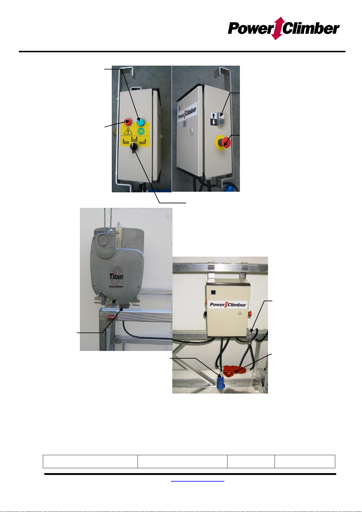
6. Automatic Levelling System
The central control box is fitted with an automatic levelling system that allows the
platform to maintain a stable horizontal position. An out of level condition can occur when
one of the hoists is working faster than the other, or if the load in the platform is not
evenly distributed.
When the platform is in motion, the automatic levelling system stops the hoist that is
going too fast and allows the other hoist to catch up. When both hoists are level again,
the levelling system is deactivated and both hoists will function simultaneously.
The automatic levelling system is activated when the platform is out of level by 3-6°.
The Automatic Levelling System can be tested by using the hoist selector switch to
create and out of level condition. Once the platform is out of level, check that the hoist
that is too high no longer works in the ’up’ direction and the hoist that is too low no longer
works in ‘down’ direction.
7. Overheating protection for hoist electric motor
The hoist motors are fitted with a thermal contact, which cuts power to the motors in case
of overheating.
When the overheating protection is activated, the ‘up’ movement is halted.
If a hoist motor has overheated, allow it to cool down to continue.
The overheating protectors of both hoists are connected in series. If one overheating
protector is triggered, then the ‘up’ movement of both hoists is halted.
8. Overspeed Safety device (OPTIONAL)
The overspeed safety device locks onto the suspension rope when the suspension rope
passes through the hoist (descent speed) at more than 15 m/min. The overspeed safety
device can also be triggered manually by pressing the manual release button.
To reset the overspeed safety device, first drive the hoist up a few centimetres and then
turn the reset knob clockwise in the direction of the arrow.
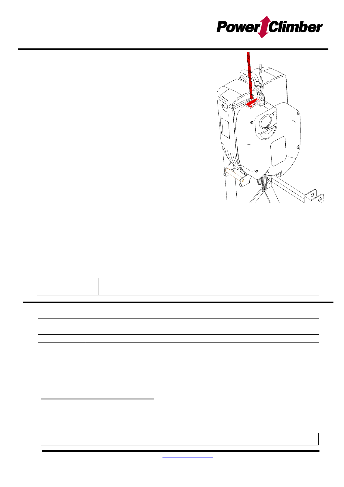
9. Use of Handwheel to reset safety device in case of power failure
If the slack rope safety device or overspeed safety device (optional) has been activated
and there is no power to the platform, it will be necessary to wind the hoist up a few
centimetres manually, to be able to reset the safety device.
1. Pull out main power plug to cut off power supply.
2. Remove plastic plug in the motor cover to expose shaft for the handwheel.
3. Remove the hand wheel from its storage position and insert shaft into hub.
4. Wind the hoist in the up-direction counter-clockwise ½ turn at the same time as you
pull up on the brake lever to open the brake.
5. Release brake lever and repeat.
TIP: Grab the hand wheel firmly while opening the brake to prevent it from turning and
going back down.
6. The overspeed safety device (optional) must be reset manually. The slack rope
safety device resets automatically.
7. Put plastic plug back on and return hand wheel to its storage position after use!
8. Plug in main power plug and resume.

Tel. +32-3-451 05 00 E-mail: Info@PowerClimber.be Fax +32-3-451 05 01
Website: www.PowerClimber.be
This document and all copies are the property of Power Climber BVBA. All dimensions and data are indicative only.
The user must ensure that the equipment complies with local rules and regulations.
Reference: 38740-E
Issue date: 24-Aug-2015
Revision: D
Page 10 of 16
TITAN STEEL WIRE ROPE
ONLY USE POWER CLIMBER RECOMMENDED STEEL WIRE ROPES
Type
Greenflex
Diameter
8.4 mm
For use with hoist model
All models of TITAN hoist
Construction
5 x 26 WSR (Warrington Seale Compacted)
+ HDPP (High Density Polypropylene) core
Structure
Right Hand Cross Lay - Light Preformed
Tolerance
(+0/-0.2mm)
Tensile strength of wires
1960 N/mm2
Minimum Breaking Load (actual)
52.3 kN
Minimum Breaking Load (calculated)
66.0 kN
Weight
0.255 kg/m
Treatment
Galvanized
Identification mark
Green strand
The end of the steel wire rope
should be brazed to form a ‘bullet’
end with a maximum length of
10mm, without loose or broken
wires.
Use protective gloves to manipulate the Steel Wire Ropes.
If Steel Wire Ropes are too long, carefully wind any extra cable into a loop (or
onto the wire holders) and tie up, leaving the coil suspended just clear of the
ground.
WARNING:
Steel Wires Ropes must be replaced in any of the following conditions:
More than 10 wires are broken on a length of 25cm
Excessive corrosion
Damage due to heat
Reduction of the nominal diameter by more than 10%
Kinking (1), crushing (2), bird caging (3) or any other distortion of the wire rope
structure.
(1) (2)
(3)
10mm

Tel. +32-3-451 05 00 E-mail: Info@PowerClimber.be Fax +32-3-451 05 01
Website: www.PowerClimber.be
This document and all copies are the property of Power Climber BVBA. All dimensions and data are indicative only.
The user must ensure that the equipment complies with local rules and regulations.
Reference: 38740-E
Issue date: 24-Aug-2015
Revision: D
Page 11 of 16
MODULO PLATFORM and SAFEFIX SYSTEM
The modular design of the MODULO®suspended platform allows you to modify the configuration
of the standard components to obtain the size platform required. These components are secured
together by using the patented SafeFix pin system, a one step “insert and snap” method to
assemble MODULO®platform components. The slotted pin is fixed in place by a spring mounted
on the stirrup or U-frame.
Insertion of the SafeFix pin
Line the pin up with the hole, so that the slot at the
base of the pin is horizontal.
Push the pin in from outside until the spring clicks in the
grooves on the shaft of the pin. If required, rotate the
pin till the slot is horizontal and the springs are in place.
Make sure the pin is secured.
Removal of the SafeFix pin
Rotate the pin ¼ turn till the slot is
vertical (and the springs are no
longer in the grooves) and pull the
pin out.
Note: The pin can be positioned with
the use of a hammer and a
screwdriver.
ATTENTION:
Springs have to be replaced when they no longer exert pressure on the grooves of the pin shaft.
2m guardrail
(PN. 61022)
3m guardrail
(PN. 61032) 3m side frame
(PN. 61030)
2m side frame
(PN. 61020)
2m deck section
(PN. 61021)
3m section deck
(PN. 61031)
U-frame
(PN. 61041)
Safefix pin
(PN. 61049)
End stirrup
(PN. 61040)
Wheel
(PN 61056)
Walk through stirrup
(PN. 61060)

Tel. +32-3-451 05 00 E-mail: Info@PowerClimber.be Fax +32-3-451 05 01
Website: www.PowerClimber.be
This document and all copies are the property of Power Climber BVBA. All dimensions and data are indicative only.
The user must ensure that the equipment complies with local rules and regulations.
Reference: 38740-E
Issue date: 24-Aug-2015
Revision: D
Page 12 of 16
ASSEMBLY: MODULO with End-Stirrup
6
1. The assembly process begins with the centre section and
continues towards each end of the platform. Start with a
one-piece U-frame and install two side frames onto the U-
frames and secure each side-frame in position with 2
SafeFix pins.
2. Continue the assembly
with U-frames and side
frames to obtain the
required platform length
and finish assembly by
installing the one-piece end-stirrup
3. Insert the aluminium floor (flat side up).
4. Check that all 4
retaining springs are
in place.
NOTE:
To remove floor, push on
the spring and lift floor at
the same time.
5. Install the guardrails, inserting a SafeFix pin in each end.
6. Install the wall rollers that can
be located anywhere along
the length of the side frame
as required.
Use minimum 2 wall rollers and put them wide apart.
WARNING:
Visually inspect all SafeFix pin connections before using the platform
Always install the guardrail before using the platform
Never stand on the guardrail or mid-rail while platform is in use
A platform with end-stirrups should not be configured with more than 3 U-frames
between suspension points
1a
2
3
5
4
1b

Tel. +32-3-451 05 00 E-mail: Info@PowerClimber.be Fax +32-3-451 05 01
Website: www.PowerClimber.be
This document and all copies are the property of Power Climber BVBA. All dimensions and data are indicative only.
The user must ensure that the equipment complies with local rules and regulations.
Reference: 38740-E
Issue date: 24-Aug-2015
Revision: D
Page 13 of 16
ASSEMBLY: MODULO with Walk Through Stirrup
Assemble the Modulo platform to the required length with
standard end-stirrups. These end stirrups will function as end
guardrails
1. Hang the mast over the mid-rail. Make sure that position is in
line with the suspension points; otherwise the slack rope
safety mechanism will not work properly.
2. Insert the lower
part into the mast
and lock with the
SafeFix pin,
making sure that
the front tab is
correctly fitted
into the channel on the front side-frame.
3. Insert the upper horizontal arm and set the
position to the required height. Lock with a
second
SafeFix pin.
4. Mount the hoist (see hoist installation) and insert both
steel wire ropes in the diverter guides.
ATTENTION: When mounting the
hoist, pay particular attention to the
orientation of the hoist.
Suspend minimum 6 kg on the
suspension rope.
Suspend minimum 12 kg on the
safety rope.
WARNING: Visually inspect all SafeFix pin connections before using the platform
On platforms with only 1 walk-through stirrup, an Overspeed safety device is compulsory.
CHECK ORIENTATION OF HOIST
ATTENTION
CHECK CENTER DISTANCES
1
2
3
4

Tel. +32-3-451 05 00 E-mail: Info@PowerClimber.be Fax +32-3-451 05 01
Website: www.PowerClimber.be
This document and all copies are the property of Power Climber BVBA. All dimensions and data are indicative only.
The user must ensure that the equipment complies with local rules and regulations.
Reference: 38740-E
Issue date: 24-Aug-2015
Revision: D
Page 14 of 16
MODULO LOAD TABLE
ATTENTION: LOAD TABLES FOR EVENLY DISTRIBUTED LOAD ONLY
Platform with end stirrups
Titan 500 kg
Titan 650 kg
Length
Configu-
ration
Max. load
per meter
Self-
weight
(platform
only)
Rated
load
Max. no.
of
persons
Rated
load
Max. no.
of
persons
(m)
(kg/m)
(kg)
(kg)
(kg)
2
2
186
95
360
2
360
2
3
3
186
110
540
3
540
3
4
2+2
186
150
700
4
720
4
5
2+3
186
165
680
5
920
5
6
3+3
186
185
660
6
960
6
7
2+3+2
186
220
630
6
930
7
8
3+2+3
186
240
610
6
910
8
9
3+3+3
150
255
590
6
890
9
10
3+2+2+3
120
295
550
5
850
9
11
3+3+2+3
120
310
540
5
780
8
12
3+3+3+3
120
330
520
5
680
7
Platform with walk through
stirrups
Titan 500 kg
Titan 650 kg
Length
Configuration
Min. Rope
Centre
Self-weight
(platform
only)
Max. rated
load
Max. no. of
persons
Max. load per
meter
Cantilever
Max. rated
load
Max. no. of
persons
Max. load per
meter
Cantilever
(m)
(kg)
(kg)
(kg)
(m)
(kg)
(kg)
(m)
1.5
2
n.a.
150
360
2
186
1.0
360
2
186
1.0
3
3
2
165
540
3
186
0.5
540
3
186
0.5
4
2+2
2
205
720
4
186
0.5
720
4
186
0.5
5
2+3
3
225
500
5
171
0.5
900
5
186
0.5
6
3+3
4
240
500
5
141
0.5
840
6
168
0.5
7
2+3+2
5
280
400
4
120
1.0
840
7
120
1.0
8
3+2+3
6
295
350
3
120
1.0
640
7
120
1.0
9
3+3+3
7
310
350
3
120
1.0
560
6
120
1.0
10
3+2+2+3
8
350
300
2
120
1.0
480
5
120
1.0
11
3+3+2+3
9
370
300
2
120
1.0
480
5
120
1.0
12
3+3+3+3
9
385
250
2
120
1.5
400
4
120
1.5
13
3+2+2+3+3
10
425
250
2
120
1.5
400
4
120
1.5
14
3+3+2+3+3
10
440
250
2
120
2.0
320
3
120
2.0
15
3+3+3+3+3
11
455
200
1
120
2.0
320
3
120
2.0
16
3+3+2+2+3+3
12
495
200
1
120
2.0
320
3
120
2.0
Note: Other numbers of cantilever and loadings upon request

Tel. +32-3-451 05 00 E-mail: Info@PowerClimber.be Fax +32-3-451 05 01
Website: www.PowerClimber.be
This document and all copies are the property of Power Climber BVBA. All dimensions and data are indicative only.
The user must ensure that the equipment complies with local rules and regulations.
Reference: 38740-E
Issue date: 24-Aug-2015
Revision: D
Page 15 of 16
PRECAUTIONS
See European Standard EN1808 for details on Applications that are excluded from the
EN1808 and other relevant exclusions.
TSP= Temporary Suspended Platform
1. Power Supply to the TSP must be fitted with
a) Main switch
b) Residual current device (or earth leakage circuit breaker) of 30 mA
c) Overcurrent protective device (automatic fuse Type C)
Note: check that the specifications of the electrical supply cable match the power requirement
of the platform and will avoid a voltage drop due to cable length.
2. Weather conditions
Temperature range: -10ºC and +55º C
Humidity range: 30 % - 95 %
Contaminants: Degree of protection IP 54
Max. wind speed: 12.5m/s (see note)
Note: For TSP with a lifting height over 40m and intended to be used on locations exposed to
wind speeds over 14 m/s, an adequate restraint system shall be provided.
3. Precautions prior to use
a) Before using the equipment, operators must carry out the daily checks and make sure that
the equipment is in perfect working condition.
b) Before use, modular TSP equipment must be checked to prevent mixing of inappropriate
components.
c) Before use, check that sufficient space is available for operating the TSP.
d) Before using the equipment the suspension system must be checked to ensure the
stability of the TSP at all times.
e) In case the area below the TSP is open to the public, preventive measures have to be
taken to safeguard the people below (e.g. barriers, roof protected walkways, etc.).
f) All hazards related to the platform encountering obstructions are not completely covered
by the TSP’s safety devices. The operator shall check for obstructions along the travel of
the platform.
g) Overload detection device may not protect TSP platforms in all configurations. The
operator shall check that the loading of the platform is in accordance with the rated load
indicated on the nameplate.
h) An area must be available to allow operators to get on and off the platform.
4. Precautions during use
a) The operators must stop working with the equipment and notify the supervisor if faults,
damage to the equipment or other circumstances may jeopardize safety.
b) A suitable communication between the operator and the supervisor is recommended.
5. Suspension System
a) The platform can be suspended on different types of suspension systems such as roof
beams (with counterweights), parapet clamps, davits, fixed suspension points, custom
made suspension systems, roof rigs made from tubular scaffolding etc.
b) Roof systems to be calculated for a max. load of W.L.L. x 3 (Maximum allowable stresses
below yield.)
c) Check that roof beams are properly counterweighted (if applicable).
d) Ensure that the suspension rig is directly above the platform prior to installation.

Tel. +32-3-451 05 00 E-mail: Info@PowerClimber.be Fax +32-3-451 05 01
Website: www.PowerClimber.be
This document and all copies are the property of Power Climber BVBA. All dimensions and data are indicative only.
The user must ensure that the equipment complies with local rules and regulations.
Reference: 38740-E
Issue date: 24-Aug-2015
Revision: D
Page 16 of 16
TITAN DAILY CHECKLIST
TESTS MUST BE CARRIED OUT
EVERY TIME BEFORE USING THE PLATFORM
1
Visually inspect the platform for damaged, loose or missing parts.
2
Check the suspension system for stability before launching the platform.
Check that all counterweights are in place and secured.
Check that all steel wire ropes are hooked on properly to the suspension system
3
Check that the GREEN ‘OK’ indicator light on the CCB is ON.
4
Check that the ‘Up/Down’ push buttons and the hoist selector switch are
functioning.
5
Push emergency stop button and check that the platform cannot go up or down.
(turn button in direction of arrow to reset)
6
Push down on the Top Limit Switch and check that
it cuts the ‘up’ direction, but that platform can be
driven in the ‘down’ direction.
Repeat procedure for other hoist.
7
Push the UP direction followed by activating the overload switch manually. The UP
and DOWN direction must be cut off as long as the overload switch is activated.
This test must be performed when the cover of the motherboard was removed
from the hoist.
Drive the platform 1-2 meters off the ground to continue the tests
8
a) ON ONE HOIST ONLY, Pull on the ‘No Power’
emergency descent lever and check that the hoist
can be lowered at a controlled speed.
b) Continue releasing the service brake until the
slack rope safety device is activated (about 14
degrees) and keeps the platform from tilting further.
c) Repeat the procedure by manually lowering the
other end of the platform.

Tel. +32-3-451 05 00 E-mail: Info@PowerClimber.be Fax +32-3-451 05 01
Website: www.PowerClimber.be
This document and all copies are the property of Power Climber BVBA. All dimensions and data are indicative only.
The user must ensure that the equipment complies with local rules and regulations.
Reference: 38740-E
Issue date: 24-Aug-2015
Revision: D
Page 17 of 16
TITAN DAILY CHECKLIST
9
Run the platform to the top and during travel inspect the steel wire ropes for kinks,
broken wires or other damage.
Inspect the trailing electrical supply cable for damage.
At the top of travel, check that the top limit switch striker plates are correctly fitted
and also that the top limit switches are operated by the striker plates.
DO NOT USE EQUIPMENT THAT IS NOT OPERATING PROPERLY
NEVER OVERRIDE LIMIT SWITCHES AND SAFETY DEVICES
This manual suits for next models
4
Other Power Climber Chain Hoist manuals
Popular Chain Hoist manuals by other brands

Ingersol Rand
Ingersol Rand LC2A Series Product information

Sievert Crane & Hoist
Sievert Crane & Hoist CM BANDIT Operating, Maintenance & Parts Manual

Planeta
Planeta EHW-60 instruction manual

LEVEX
LEVEX SLB025 User instructions

POWERTEX
POWERTEX PACB-S1 Series Instructions for use

SVERO
SVERO 1411 User instructions