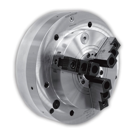
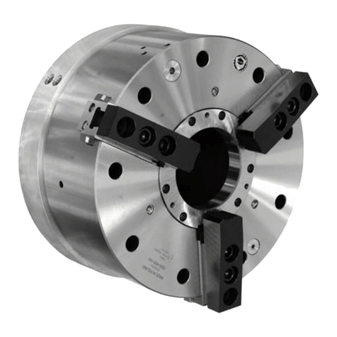
Bison 2500 User manual

2500
INSTRUCTION MANUAL [Page 3]
The manual covers assembly, operation and
maintenance of power chucks with an integrated
pneumatic cylinder.
NOTE: Please read the instructions thoroughly
before attempting to operate on chuck!
BEDIENUNGSANWEISUNG [Seite 27]
Die vorliegende Bedienungsanleitung umfasst
Betrieb, Montage und Wartung der oben genannten
Kraftspannfutter mit integriertem Pneumatikzylinder.
ANMERKUNG: Vor der Arbeit lesen Sie bitte die
Bedienungsanleitung!
[Strona 15]
Instrukcja obejmuje montaż, eksploatację
i konserwację uchwytów mechanicznych
zintegrowanych z cylindrem pneumatycznym.
Инструкция включает в себя монтаж, эксплуатацию
и консервацию mеханическиx патронoв
интегрируемыx с пневматическим цилиндром.
!!
!!
MADE IN EU


1
Dear Customer,
On behalf of BISON-BIAL S.A. we would like to thank
you for choosing our product!
We believe that the use of our products will meet
your highest expectation.
Our staff will provide you with any technical
information and assistance as well as help you
choose the optimal products, spare parts, or
accessories from the wide range of BISON-BIAL S.A.
products all tailored for your specic needs.
The product you have purchased is covered with a
warranty, which is part of the service we provide to
our valued customers. Please take time to carefully
familiarize yourself with the included warranty
conditions.
Kind Regards,
BISON-BIAL S.A.
Sehr geehrter Kunde,
im Namen von BISON-BIAL S.A. bedanken wir uns
für den von Ihnen getätigten Kauf!
Wir hoffen, dass die Nutzung unserer Produkte Sie
zufrieden stellt und Ihnen viel Freude bringen wird.
Unsere Mitarbeiter stehen Ihnen jederzeit mit allen
technischen Informationen zu unseren Produkten
zur Verfügung und beraten Sie gerne hinsichtlich
der Auswahl von passenden Ersatzteilen und
geeignetem Zubehör.
Im Rahmen unserer Serviceleistungen gewähren
wir auf das von Ihnen erworbene Produkt eine
Garantie. Wir bitten Sie daher, die beigefügten
Garantiebedingungen aufmerksam zu lesen.
Mit freundlichen Grüßen,
BISON-BIAL S.A.
Szanowny Kliencie,
W imieniu BISON-BIAL S.A. pragniemy
podziękować za dokonane zakupy. Mamy nadzieję,
że użytkowanie naszych wyrobów przyniesie
Państwu zadowolenie i wiele satysfakcji.
Nasi pracownicy udzielą Państwu wszelkich
informacji technicznych i będą służyli pomocą
w doborze oprzyrządowania produkowanego przez
rmę BISON-BIAL S.A.
Zakupiony przez Państwa wyrób jest objęty
gwarancją, będącą jednym z elementów serwisu
świadczonego naszym drogim Klientom.
Z poważaniem,
BISON-BIAL S.A.
Уважаемые Клиенты,
От имени BISON-BIAL S.A. хотим поблагодарить
за покупку наших продуктов. Надеемся, что
пользование ними даст Вам удовольствие и много
удовлетворений.
Наши сотрудники дадут Вам всякие нужные
технические справки а также окажут помощь
при выборе оснастки, производимой фирмой
BISON-BIAL S.А.
Мы предоставляем гарантию на приобретенный
Вами продукт, которая является одной из частей
сервисного обслуживания наших дорогих
Клиентов.
С уважением,
BISON-BIAL S.A.

2

3
ENGLISH
1. APPLICATION
2. WORK SAFETY CONDITIONS
3. CHUCK STRUCTURE
4. TECHNICAL DATA
5. COMPRESSED AIR DISTRIBUTION SYSTEM
5.1. Clamping of the workpiece
5.2. Unclamping of the workpiece
6. INSTALLATION ON THE LATHE
6.1. Preparing the lathe
6.2. Preparing the chuck for mounting
6.3. Preparing the chuck for operating
7. DISMOUNTING AND MOUNTING
7.1. Dismounting the chuck
7.2. Mounting the chuck
8. MAINTENANCE
9. TROUBLESHOOTING
10.WARRANTY TERMS AND CONDITIONS
CONTENTS
4
4
5
7
7
7
8
9
9
9
10
10
10
11
11
12
12
PAGE

4
ENGLISH
2. Work safety conditions
1. application
The power chucks with an integrated pneumatic cylinder and a fixed pressure distributor (attached to the
headstock) are designed for accurate turning of very long components such as tubes with large diameters and
similar workpieces.
Chucks can work on the lathes with a spindle, ensuring mounting of two chucks on its both ends. The double
spindle configuration increases clamping force and clamping stability.
The clamping/ unclamping is performed at stopped spindle by intake/ exhaust operation into the cylinder
chambers with a compressed air.
■manufactured from high grade alloy steel, which
extends machine life while providing higher rigidity
and greater wear resistance,
■hardened and ground working surfaces ensure
longer life with maintained accuracy and
repeatability,
■rigid structure and large through-hole,
■master jaws secured against throw-off,
■master jaws and drawbar lubricated directly,
Chuck technical features: ■built-in a non-return valve maintains a constant
pressure ow in piston chambers in case of
supply pressure drop
■air pressure safety control distributor in the
clamping chambers,
■jaw stroke control device,
■plain back mounting with clamping from the
front,
■external clamping of the workpiece (rapid idle
and slow gripping stroke)
■unbalance class G 6,3.
1. Please read the instructions thoroughly before
attempting to operate on the chuck and strictly
adhere to this manual.
2. In case of fault, malfunction or damage of the
chuck, immediately stop working and contact
technical supervision.
3. Repair and overhaul of the vise must be
performed only by an appropriately qualied
person.
4. Any set-up works, maintenance and all other
application work must be carried out at
stopped spindle and disconnected pressure
distributor only.
5. The max. data as max. pressure, max. speed
and max. gripping force are engraved on the
chuck body. They must not be exceeded in
any case.
6. Always use original BISON top jaws only.
7. Check the sealness of both cylinder chambers
regularly.
8. The steady pressure distributor must be
mounted steady on the chuck to eliminate
throw-off risk.
Except as listed above, the operator should follow
the existing local Health & Safety Regulations.
By following the instructions covered in this manual,
a long life and trouble free operation of the vise will
be guaranteed.
NOTE: The spindle rotation can be turned
on only when there is no pressure in air
supply hoses!
!NOTE: The manufacturer assumes
no responsibility or liability for any
claims arising due to not following the
instructions covered in this manual.
!
NOTE: The manufacturer reserves the
right to make improvements or changes
to the product without describing herein.
!

5
ENGLISH
Chuck structure type 2500
The power chuck consists of a high alloy steel body where the pneumatic cylinder connected with a drawbar
and three master jaws is mounted. The jaws are adapted for mounting of special hard top jaws. The jaw serration
is equal to 3/32’’ x 90°.Plain back mounting with clamping from the front. Power supply of the chuck through
a fixed pressure distributor attached on the adapter plate side.
The double-acting pneumatic cylinder use the force of the air pressure, moving the drawbar connected with jaws.
The axial force of the drawbar is transferred to the jaws through the two-angle wedge system. The compressed
air pressure is transmitted through a safety control distrubutor (mounted on the adapter plate side). A non-return
valve maintains a constant pressure flow in the piston chamber in case of supply pressure drop.
3. cHUck strUctUre
Fig. 1
g
h
l
k
A1
l
B
B
A
A
M6
20
10
6 otw. M8
12
F
L
B-B
air pressure
control device
d
e
D
B
S
E
H
G
M6
12
A2
J
P
max 5
min 0
N
V
M
A
c
f
O
12
C
T
K
U
R
F
F
b
A-A
jaw stroke
control device
3/32''x90

6
ENGLISH
Chuck component parts type 2500
Fig. 2
Chuck component parts type 2500
NOTE: The manufacturer does not provide any pneumatic equipment, proximity switches that
work with chuck control devices as well as any parts working with the proximity switch devices.
!
-Body -Non-return valve -O-ring (piston w/ drawbar)
-Drawbar -Control distributor -Baffle O-ring
-Master jaw -Plug (pressure control) -Adapter plate O-ring
-T-nut -Pressure distributor -O-ring (drawbar w/ cover)
-Cover -Cover screw -O-ring (baffle w/ drawbar)
-Adapter plate -Cylinder baffle screw -O-ring (adapter plate w/ cover)
-Cylinder piston -Piston screw -O-ring (piston w/ cylinder)
-Cylinder baffle -Adapter plate screw
-Valve cover -Upper hard jaw screw
1
2
6
3
4
5
10
11
13
12
14
15
19
20
22
21
23
24
8
716
17
25
918

7
ENGLISH
4. tecHnical data
Basic technical data is indicated in Tab.1. and Tab.2.
Parameter Chuck size
400-140 500-230
Min. working pressure [MPa] 0,35 0,35
Max. working pressure [MPa] 1 1
Clamping force (0,6 MPa) [kN] 90 170
Air consumption for 1 cycle [l] 3 7
Max. admissible speed [rpm] 1300 1000
Weight w/o top jaws [kg] 211 335
Tab. 1
Parameter Chuck size
400-140 500-230
A467 570
A1 483 615
A2 455 -
Total jaw stroke 19 25,4
Clamping jaw stroke 78,6
Rapid jaw stroke 12 16,8
B241 277
C246 282
D310 -
E8 8
F374 474
G9xM12 12xM12
H24 26
J400 500
K415 465
L448 550
M26 26
NG3/8’’ G3/8’’
O20 20
P140 230
R205 306
S4 4
T4 4
U5 -
V37 37
b min 100 149,2
b max 119 174,6
c min 15,5 15,5
c max 68 81
dM20 M20
e38 38
f120 131,5
g25,5 25,5
h60 60
l20°15°
k30°30°
Tab. 2
5. air distribUtion system
NOTE: The power chuck with an integrated
pneumatic cylinder use the force of the
compressed air pressure (clamping and
unclamping of the workpiece), can be
performed at stopped spindle only.
!
NOTE: The delivered airow must be clean,
undamped and correctly lubricated.
!
The compressed air that flows into the ‘clamping’
chamber of the pressure distributor causes
a deformation of the profile seal, while sealing the
connection of a distributor and chuck body, then the
air flows through a non-return valve – resulting in:
■Connection of the cylinder ‘unclamping’
chamber with the atmosphere,
■The air flows into the cylinder ‘clamping’
chamber while displacing the piston of the
position - connected permanently with the
pulling sleeve, which drives the master jaw
through the wedge system,
■The two-angle wedge system, provides jaw
working motion with two speeds:
–rapid idle stroke (long jaw stroke),
–slow motion (short jaw stroke).
■The above results in clamping of the workpiece.
The compressed air supply cut-off in the distributor
chamber is causing:
■Profiled seal returns to its original position
(seal moves out from the surface of chuck
body),
■The non-return valve cuts-off the connection
of the supplied cylinder chamber with pressure
distributor,
■The non-return valve maintains the
pressure in the cylinder chamber (after
power cut-off, the air in the chamber is
under pressure).
The workpiece is clamped and ready for machining.
5.1 Clamping of the workpiece

8
ENGLISH
The compressed air that flows into the
‘unclamping’ chamber of the pressure distributor
causes a deformation of the profile seal, while
sealing the connection of a distributor and chuck
body, then the air flows through a non-return valve
– resulting in:
■Connection of the cylinder ‘clamping’
chamber with the atmosphere,
■The air flows into the cylinder ‘unclamping’
chamber while displacing the position of
the piston - connected permanently with the
pulling sleeve, which drives the master jaw
through the wedge system,
■The two-angle wedge system, provides jaw
working motion with two speeds:
–slow motion (short jaw stroke),
–rapid idle stroke (long jaw stroke).
■The above results in clamping of the
workpiece.
The compressed air supply cut-off in the
distributor chamber is causing:
■Profiled seal returns to its original position
(seal moves out from the surface of chuck
body,
■The non-return valve cuts-off the connection
of the supplied cylinder chamber with
pressure distributor,
■The non-return valve maintains the
pressure in the cylinder chamber (after
power cut-off, the air in the chamber is
under pressure).
The workpiece is unclamped.
5.2 Unclamping of the workpiece
1. jaw stroke control device
■the workpiece is clamped correctly, when the
control device arbor is in outward position,
■the control device arbor is in inward position
when:
–jaws are in the range of the rapid idle
stroke,
–jaws are in the end-point clamping range.
2. air pressure control device in the ,clamping’
chamber
■when the pressure in the ‚clamping’ chamber
is set correctly - the control device arbor is in
inward position,
■the pressure drop in the ‚clamping’ chamber
below the minimum set value (default setting of
the minimum pressure at 0,35 [MPa]) effects of
ejecting the control device arbor outwards.
The control devices should be integrated with the machine
safety control system, that prevents from operating, when
the pressure in the cylinder chamber or clamping of the
workpiece is incorrect.
The control device arbors have M6 holes designed for
clamping of any parts working with the proximity switch
devices (Fig. 1.).
Chucks type 2500 are equipped with control
devices:
NOTE: Never clamp the workpiece when the
jaws are in the range of the rapid idle stroke
or in the end-point of the clamping range (the
jaw stroke control device arbor is in inward
position).
!
..

9
ENGLISH
NOTE: Never place the chuck onto jaws!
!
The workstation should be equipped with the
compressed air connection, that contains a connector
block and shut-off valve (block valve).
The control system and tooling, operator should get
by himself or order.
For controlling, use the 2-way 3-position valve
located in a mid-position, connecting the chamber to
the atmosphere. (Fig. 4).
Fig. 4
Control valve scheme
NOTE: The manufacturer does not provide
any pneumatic equipment, proximity
switches that work with chuck control
devices as well as any parts working with
proximity switch devices.
!
6.2 Preparing the chuck for mounting
■open the package,
■check, if the delivered product is fully completed,
■remove the distributor from the chuck,
■lift the chuck up via an eyebolt and remove from
the package,
■place the chuck down in a position preventing
chuck motion,
To mount the chuck on the lathe, please
proceed as follows:
■lift the chuck up via hoist and an eyebolt,
■place the distributor onto the chuck,
■center the spindle towards to chuck, so that the
safety valve pin catches the adapter plate I.D.
hole of Ø14mm,
■mount the chuck to the adapter plate,
■mount the pressure distributor,
■check, whether during the rotation the chuck is
not rubbing the pressure distributor, if it does then
needs to be centered,
■when dismounting from the lathe, please proceed
in the reverse order.
6. installation on tHe latHe
6.1. Preparing the lathe
The machine safety control sytem should prevent
turning on the spindle rotation, while the pressure
distributor is ‚under pressure’.
The lathe should be equipped with a special ring or
bracket, supporting the distributor in centric and non-
contact position with the chuck, as well as the adapter
plate (for chuck mount). The operator should get these
elements by himself or order.
Stiffly and permanently mount the ring or brackets
onto the lathe spindle or spindle bearing cover; the
adapter plate on the spindle end. The adapter plate
requires the I.D. hole of Ø14mm - as far as the safety
valve pin appears (dimensions ‚L’ and ‚F’ according to
Fig. 1. and Tab. 2.).
After the mount, the ring or brackets, and adapter
plate should meet the conditions indicated in Fig. 3.,
dimensions according to Tab. 2.
..
Fig. 3
Chuck adapter plate and distributor bracket
4 2
3 1

10
ENGLISH
6.3 Preparing the chuck for operating
■on the control arbors, mount the parts that work
with proximity switches,
■mount the proximity switches that work with chuck
control devices,
■while using the exible hoses, connect the
distributor together with a connector block,
■mount the top jaws, so that after clamping of the
workpiece, the jaw stroke control device arbor is in
‚outward’ position.
To get the chuck ready for operating, please proceed as follows:
■the jaw mounting bolts must be tightened to the
specied torque,
■perform several clamp/ unclamp test operations,
■it is recommended to check the jaws clamping
force and adjust air pressure to working
conditions,
■while replacing the jaws, clean the teeth surfaces
thoroughly.
NOTE: After mounting the control tooling and device into the chuck of 2500 type, the machine
should meet the essential requirements complied in the Machinery Directive 98/37/ WE. According
to the Directive, the manufacturer is the party who has mounted the control tooling and device and
is obliged to issue the WE declaration of conformity.
!
NOTE: When using the special top jaws, the operator should check on (determine) the correct
jaw clamping force.
!
NOTE: Never place the chuck onto jaws!
!
7. dismoUnting and moUnting
NOTE: Any chuck operation work must be carried out after previous pressure alignment with the
atmosphere in the chuck chambers.
!
■disconnect the air supply from the chuck,
■disconnect the chuck air feeding hoses,
To align the pressure with the atmosphere in the chuck chambers, please proceed as follows:
■loosen the pressure control plug (12),
■loosen the valve cover (9).
■align the pressure with the atmosphere in the chuck
chambers,
■dismount the chuck from the lathe via hoist and
an eyebolt,
■dismount the top jaws,
■dismount the pressure distributor,
■place the chuck down in a position preventing
chuck motion,
7.1. Dismounting the chuck
■place the chuck with jaws upside down on
a special pad, so the jaws can relocate easily,
■unscrew the adapter plate screws (17),
■take off the adapter plate screws (6),
■unscrew the piston screws (16),
■take off the cylinder piston (7),
■unscrew the cylinder bafe screws (15),
■take off the cylinder bafe (8),
■take off the drawbar (2),
■take off the master jaws (3).
■take off the jaw stroke control device.
■unscrew the cover screws (14),
■take off the cover (5),
■take off the control pressure distributor,
■unscrew the valve cover (9)
To dismount the chuck, please proceed as follows:

11
ENGLISH
To check the pressure drop in the clamping
chamber, please proceed as follows:
■unscrew the plug (12) and in its place screw the
pressure gauge,
■ll the cylinder chamber with air at a pressure equal
0.5 MPa,
■turn off the chuck power supply,
■check, whether there is no air pressure decrease in
the chuck cylinder chamber,
■perform the chuck leak tightness testing several
times,
■testing should be carried out for the two chambers
of the pneumatic cylinder.
■unscrew the control device locking screw,
■while using a screw located inside the device,
adjust the spring tension, so that when the pressure
drops to 0,15 [MPa], the control arbor is transfered
to the extreme position (such as when there is no
pressure in the chamber),
■screw the control device locking screw,
■testing should be carried out for the two chambers
of the pneumatic cylinder.
To adjust the pressure control distributor in the
chuck pneumatic chamber, please proceed as
follows:
7.2 Mounting the chuck
Before mounting, make sure all parts are clean and dry; the lubrication holes are permeable.
To lubricate the master jaw guideways and drawbar, apply the GLEITMO-805 grease or similar; other parts
lubricate with the ŁT-43 grease.
Always tighten the mounting bolts with correct torque adequate to a bolt size and its property class.
It is recommended to replace the seals.
When mounting the chuck, please proceed in the reverse order.
NOTE: Never clean the chuck with the compressed air.
!
NOTE: Insert the jaws into the guideways marked with the same number.
!
8. maintenance
NOTE: Never clean the chuck with the compressed air.
!
1. To lubricate the master jaw guideways and drawbar, apply the GLEITMO-805 grease or similar, while for the
compressed air supply system apply the HL-32 hydraulic oil or similar.
2. It is recommended to grease the jaws at least once a week.
3. Depending on operating conditions, however at least once a year the chuck should be disassembeled. All
parts should be cleaned and the technical condition evaluated, any worn out seals replaced.

12
ENGLISH
9. troUblesHooting
The situations below indicate how to proceed, when the chuck is not working properly or malfunctioning.
Tab. 3
10. general terms and conditions of Warranty
Situation Reason Action
Chuck does not operate No pressure in the air feeding hoses.
Non-return valve has not overdriven
or is locked.
Check the power supply and control system.
Check, if during overdrive operation the
‚click’ of the distributor seals and non-return
valve appears.
Chuck does not operate although the
distributor seals and non-return valve
have ‚clicked’
Damage or blockage of some movable
parts of the chuck.
Check, if the control device (arbor) is
in a position indicating pressure in the
cylinder chamber.
Chuck does not operate although the
pressure in the cylinder chamber is
present
Chuck is locked. Dismount the chuck and check the
blockage cause.
Chuck does not release the workpiece Low pressure in the hose (A).
Non-return valve is locked.
Check the air supply pressure. (must
be not lower than 70% of the pressure
in the cylinder chamber). Check, if the
valve ‚clicks’
Non-return valve does not operate Non-return valve is locked. Remove the valve, clean the seat and replace
with new one if necessary.
Control device does not operate Damage of the control device. Remove the valve, clean the seat and
replace with new one if necessary
Pressure drop in the cylinder chamber Leaky system. Check the pressure drop; remove the
cause of leakage.
The product you have purchased is covered with
a warranty, which is part of the service we provide to our
dear Customers. Please take time to carefully familiarize
yourself with the warranty conditions listed below:
1. BISON-BIAL S.A. guarantees a smooth
operation of the purchased product in
the period of 12 months from the date of
purchase. If the purchased product has been
successfully registered on the Internet website
www.bison-bial.com the warranty period may
be prolonged up to 24 months from the date of
purchase.
2. The warranty covers defects resulting from causes
inherent in the sold product.
3. The Buyer may take advantage of the rights arising
from this Warranty on the following conditions:
1) Presenting the proof of purchase
2) Submitting the faulty product
4. The Warranty covers only products assembled and
used in accordance with the Manual.
5. Should a fault become evident in the warranty
period the Customer is asked to:
Notify BISON-BIAL S.A. by completing the
special form provided on the internet website of
BISON-BIAL S.A. in the tab “Complaints”,
subject to the provisions of §18 of the General
Warranty Conditions, or
2) Notify BISON-BIAL S.A. in writing via mail, fax
or email sent to the following email address:
6. The Buyer is obliged to include in the complaint
notication the type and size of the purchased
product and its serial number, describe the defect
of the product or how the damage occurred. The
notication must be attached with the invoice
under which the product was purchased.

13
ENGLISH
The situations below indicate how to proceed, when the chuck is not working properly or malfunctioning.
7. Before submitting the product to BISON-BIAL S.A.
the Buyer is obliged to clean, preserve, and secure
the product against damage and destruction that
may occur during transport. This also applies to
cases when the product is submitted to BISON-
BIAL S.A. through third parties.
8. The notied complaint will be processed under the
condition of returning the product in its original
packaging with its complete equipment and all the
documents (Manual and Quality Certicate).
9. The notied complaint will be processed within
30 days from the date of submitting the product to
BISON-BIAL S.A. However, should there be a need
to conduct necessary tests or expert’s studies,
or should it be impossible to correct the notied
defects for reasons beyond the control of BISON-
BIAL S.A. other than the ones indicated above, the
aforementioned period shall be extended by the
time necessary to correct the defects.
10. If the Buyer’s complaint, as referred to in §9 of
the General Warranty Conditions, is classied as
reasonable, BISON-BIAL S.A. shall correct the
defect within 21 days from the date on which the
complaint was recognized as reasonable, subject
to the provisions of §11 of the General Warranty
Conditions. The time of correcting the defect may
be prolonged should it be impossible to correct the
recognised defect for reasons beyond the control
of BISON-BIAL S.A.
11. The Buyer is entitled to have the product replaced
with a new one if:
1) There have been ve in-warranty repairs done
during the Warranty Period of BISON-BIAL
S.A.;
2) It is impossible to correct the defect;
3) BISON-BIAL S.A. does not correct the defect
within the time limit specied in §10 of the
General Warranty Conditions, subject to the
provisions of §13 of the General Warranty
Conditions.
12. BISON-BIAL S.A. shall replace the product with
a new one or provide the Buyer with a refund
within a period agreed on with the Buyer; but not
longer than 90 days from the date on which one
of the conditions specied in §11 of this General
Warranty Conditions occurred.
13. Rights arising from the Warranty may be lost
should the following conditions occur:
1) Improper use of the products, use of the
products not in compliance with their purpose,
instalment and exploitation as well as a
maintenance not compliant with the principles
included in the Manual;
2) The product has been repaired at an
unauthorised service point;
3) The Buyer has had arbitrary changes made
to the construction of the product or had the
product modied;
4) The product has been used with non-original
spare parts or equipment other than the
original one;
5) Use of consumables – lubricants or oils
– other than the ones recommended in the
manual to BISON-BIAL S.A. products.
14. Should the notied complaint on a defect appear
groundless, BISON-BIAL S.A. has the right to
charge the Buyer with the costs of return and
delivery of the product, as well as with the costs
of the control tests.
15. BISON-BIAL S.A. shall not be held responsible
for the consequences of the use of its products in
ways incompatible with their purpose, the use of
its products after modications and contrary to the
provisions included in the Manual.
16. The court competent to solve any disputes arising
in relation to the sale of the products is the court of
competent venue for BISON-BIAL S.A.
17. The fact that the Buyer has exercised his warranty
rights does not result in the transfer of the
ownership of the product to BISON-BIAL S.A.
18. The warranty on the product sold does not exclude,
limit or suspend any rights of the Buyer that result
from the nonconformity of goods with the contract
as referred to in the Act of 27th July 2002 on
special conditions of consumer selling and on
amending the Civil Code [Journal of Laws] No.
141, item 1176 as amended).
19. The provisions of this Rules and Regulations
regulating the rights or obligations of the Customer
in a manner contrary to or inconsistent with the
rights of consumers arising from the generally
applicable laws or adversely affecting consumers’
interest do not apply to consumers. This applies
in particular to §16 of the General Warranty
Conditions.

14
ENGLISH

POLSKI
15
1. ZASTOSOWANIE
2.
3.
4. DANE TECHNICZNE
5.
5.1. Zamocowanie przedmiotu obrabianego
5.2. Odmocowanie przedmiotu obrabianego
6.
6.1. Przygotowanie obrabiarki do zamontowania uchwytu
6.2. Przygotowanie uchwytu do zamontowania na obrabiarce
6.3. Przygotowanie uchwytu do pracy
7.
7.1. D
8. KONSERWACJA
9.
10.WARUNKI GWARANCJI
16
16
17
19
19
19
20
21
21
21
22
22
22
23
23
24
24
STRONA

POLSKI
16
2. Warunki BezpieczeństWa pracy
1. Każdy obsługujący uchwyt przed przystąpieniem
do jego eksploatacji powinien zapoznać się
z niniejszą instrukcją i ściśle jej przestrzegać.
2. Po zauważeniu nieprawidłowości działania
lub uszkodzenia uchwytu należy przerwać
natychmiast na nim pracę i poinformować
o tym dozór.
3. Naprawy i remonty uchwytu mogą być
dokonywane tylko przez osoby mające
odpowiednie kwalikacje.
4. Wszelkie prace instalacyjne, konserwacyjne
i inne prace obsługowe mogą być wykonywane
wyłącznie przy zatrzymanym wrzecionie
i odłączonym zasilaczu sprężonego powietrza.
5. Dopuszczalne parametry techniczne takie jak
maks. ciśnienie, maks. szybkość obrotów,
maks. siła zacisku są cechowane na
uchwycie. W żadnym przypadku nie wolno ich
przekraczać.
6. Zaleca się używanie wyłącznie oryginalnych
górnych szczęk rmy BISON-BIAL.
7. Zaleca się okresową kontrolę szczelności
komór cylindra.
8. Zasilacz powinien być prawidłowo
zamocowany do korpusu obrabiarki w celu
wyemilinowania ryzyka wypadnięcia.
Poza wymienionymi wymaganiami obsługujący
powinien stosować się do lokalnych przepisów BHP
obowiązujących w jego macierzystym zakładzie.
Przestrzeganie zaleceń podanych w niniejszej instrukcji
zapewnia długą żywotność uchwytów i niezawodną ich
pracę.
1. zastosoWanie
Uchwyty mechaniczne zintegrowane z cylindrem pneumatycznym i nieruchomym zasilaczem (przytwierdzonym
do korpusu wrzeciennika) są przeznaczone do mocowania długich rur o dużym przekroju średnic lub innych detali
o podobnym kształcie.
Uchwyty można stosować na tokarkach z wrzecionem umożliwiającym mocowanie dwóch uchwytów na obu jego
końcach. Układ wrzeciona z dwoma uchwytami zwiększa siłę i stabilność mocowania długich detali.
Mocowanie/ odmocowywanie odbywa się przy nieruchomym wrzecionie poprzez wypełnianie/ opróżnianie komór
cylindra sprężonym powietrzem.
■wykonane ze stali stopowej, która zapewnia dużą
sztywność uchwytu i odporność na zużycie,
■hartowane i szlifowane powierzchnie
współpracujące wszystkich części gwarantują
wysoką dokładność, powtarzalność i długi okres
eksploatacji uchwytu,
■sztywna budowa oraz duży przelot,
■szczęki podstawowe zabezpieczone przed
wypadnięciem w przypadku awarii uchwytu,
■bezpośrednie smarowanie szczęk i tulei ciągnącej,
■zawór zwrotny zapewniający utrzymanie ciśnienia
w zasilanych komorach w sytuacji spadku
ciśnienia zasilającego,
■urządzenie kontrolne do monitorowania ciśnienia
w komorze mocującej w czasie pracy uchwytu,
■urządzenie kontrolne do monitorowania skoku
szczęki,
■osadzenie cylindryczne z mocowaniem od czoła
■podwójny skok szczęk (szybki dobieg i powolne
mocowanie),
■niewyważenie w klasie G 6.3.
producenta.

POLSKI
17
Budowa uchwytu 2500
Uchwyt składa się z korpusu stalowego, w którym jest zamontowany cylinder pneumatyczny połączony z tuleją
ciągnącą i trzema szczękami podstawowymi. Szczęki są przystosowane do zamocowania szczęk górnych
twardych przestawianych. Skok ząbków wynosi 3/32’’ x 90°. Osadzenie uchytu cylindryczne z mocowaniem od
czoła. Zasilanie uchwytu poprzez nieruchomy zasilacz umieszczony od strony zabieraka.
Wbudowany cylinder pneumatyczny dwustronnego działania nadaje ruch dla tulei ciągnącej połączonej ze
szczękami. Siła osiowa tulei jest przenoszona na szczęki przez układ klinowy z dwoma kątami. Powietrze do
cylindra (przy nieruchomym wrzecionie) doprowadzane jest przez specjalny zasilacz. Uchwyty są wyposażone
w zawór bezpieczeństwa, który zabezpiecza przed spadkiem ciśnienia w komorze ciągnącej cylindra.
3. BudoWa uchWytu
g
h
l
k
A1
l
B
B
A
A
M6
20
10
6 otw. M8
12
F
L
B-B
kontrola
ciśnienia w cylindrze
d
e
D
B
S
E
H
G
M6
12
A2
J
P
max 5
min 0
N
V
M
A
c
f
O
12
C
T
K
U
R
F
F
b
A-A
kontrola
położenia szczęki
3/32''x90

POLSKI
18
- - -
- - -
- - -
- - -
-Pokrywa - -
-Zabierak - -
- - -
- -
-Pokrywa zaworu -
1
2
6
3
4
5
10
11
13
12
14
15
19
20
22
21
23
24
8
716
17
25
918
Other manuals for 2500
1
This manual suits for next models
1
Table of contents
Languages:
Other Bison Industrial Equipment manuals
Popular Industrial Equipment manuals by other brands

YOKOGAWA
YOKOGAWA AE100D instruction manual

Sit
Sit TRASCO GRMP Series Operating and maintenance manual

SnowEx
SnowEx Brine PRO 2000 manual

ABB
ABB VM1 instruction manual

Triton
Triton atmgurus ARGO SDD TO MMR50 manual

Stuart Turner
Stuart Turner Pulse Trade 25-60/130 Installation, operation & maintenance instructions

Dometic
Dometic SMX II Description and installation manual

RGB Technology
RGB Technology 106-01-02 Technical and Operational Documentation

ABB
ABB HVL 120-0.3 operating manual

Ceriotti
Ceriotti DOMO Assembly instructions

RINGSPANN
RINGSPANN EV 018EFM Series Installation and operating instructions

Slee
Slee MTR operating manual