Bison 6620 User manual

INSTRUCTION MANUAL
No 1201-01
PRECISION MACHINE VISES
TYPE 6620, 6621, 6622, 6623, 6624
Read your instructions !
„BISON” S.A.
POLAND
www.bison-chuck.com

2
TABLE OF CONTEST:
1. SCOPE OF MANUAL...........................................................................................3
2. PRECISION MACHINE VISES APPLICATIONS..................................................3
3. CONSTRUCTION OF PRECISION MACHINE VISES..........................................3
4. BASIC SPECIFICATIONS OF PRECISION MACHINE VISES.............................5
5. OPERATION........................................................................................................9
5.1.PREPARATION THE VISE TO OPERATION..................................................9
5.2.VISE POSITIONING ON MACHINE TOOL......................................................9
5.3.FASTENING VISES ON THE MACHINE-TOOL TABLE..................................9
5.4.CHANGING THE OPENING RANGE ............................................................11
5.5.CLAMPING THE WORKPIECES...................................................................12
5.6.USING THE SETS OF VISES........................................................................15
6. ACCESSORIES..................................................................................................16
6.1.STANDARD ACCESSORIES ........................................................................16
6.2.OPTIONAL ACCESSORIES..........................................................................17
7. MAINTENANCE .................................................................................................20
8. WORK SAFETY REGULATIONS.......................................................................20
9. FINAL REMARKS...............................................................................................20

3
1. SCOPE OF MANUAL
The manual covers characteristic, operating and maintenance of precision
machine vises of 6620, 6621, 6622, 6623 and 6624 type.
2. PRECISION MACHINE VISES APPLICATIONS
Precision machine vises are used for precision milling and grinding operations
on CNC and conventional machine tools. The design, accuracy and quality ensure
exact positioning the workpiece and obtaining large clamping forces. Vises may be
also set up into machining units directly on machine table for clamping large
workpieces or multi-machining.
3. CONSTRUCTION OF PRECISION MACHINE VISES
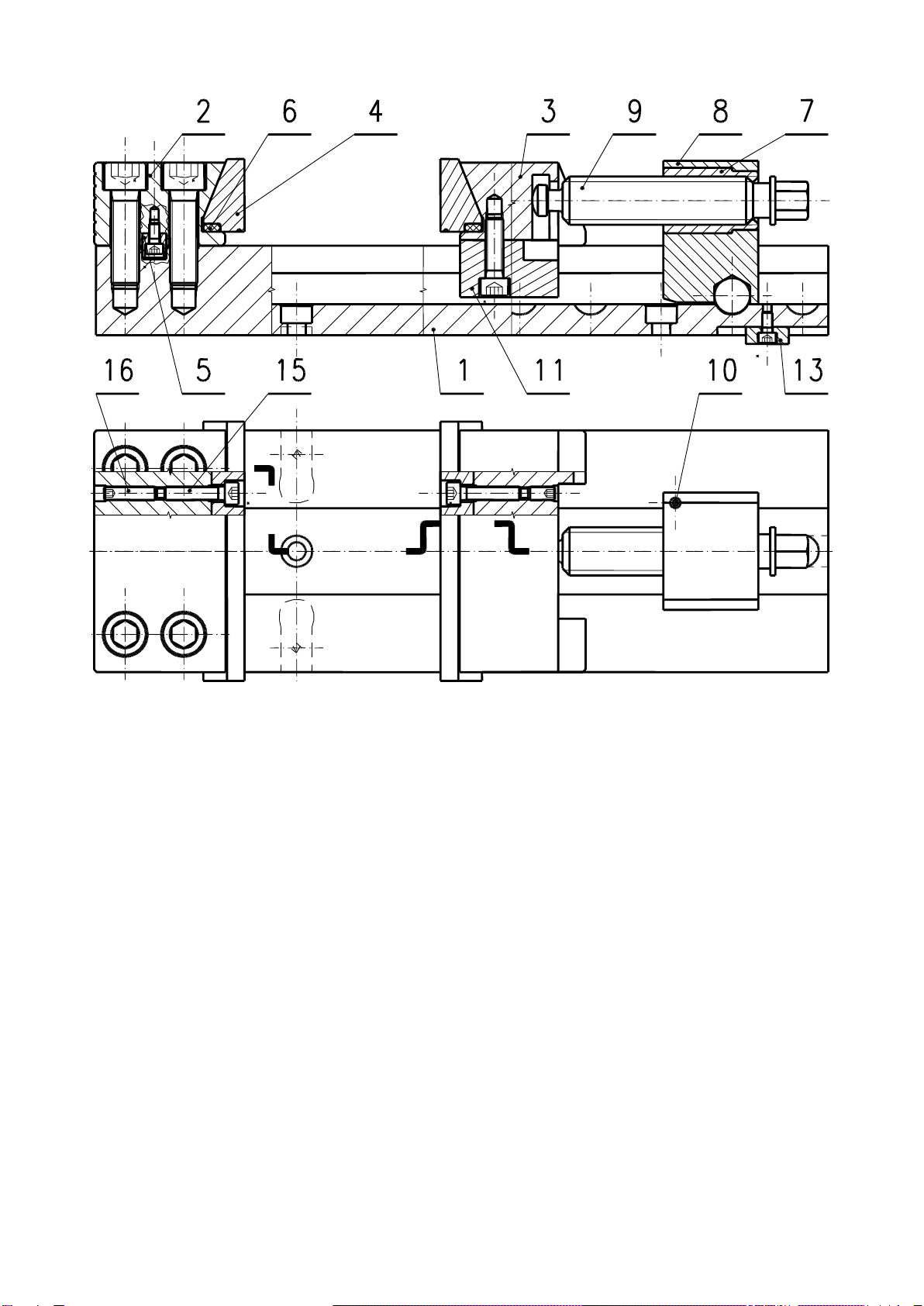
Construction of precision machine vises of 6620 is shown at Fig. 1 and 2.
Fig. 1. Construction of precision machine vises of 6620.
4
The cross-section of precision machine vise of 6620 type is shown at Fig. 2.
Fig. 2. Cross-section of precision machine vise of 6620 type
1. Base
2. Fixed jaw
3. Movable jaw
4. Clamping insert
5. Key
6. Thrust plate
7. Sleeve
8. Holder
9. Lead screw
10. Screw
11. Guide plate
12. Self-aligning guide plate
13. Fixture key
14. Clamping lug
15. Bolt
16. Screw

5
4. BASIC SPECIFICATIONS OF PRECISION MACHINE VISES
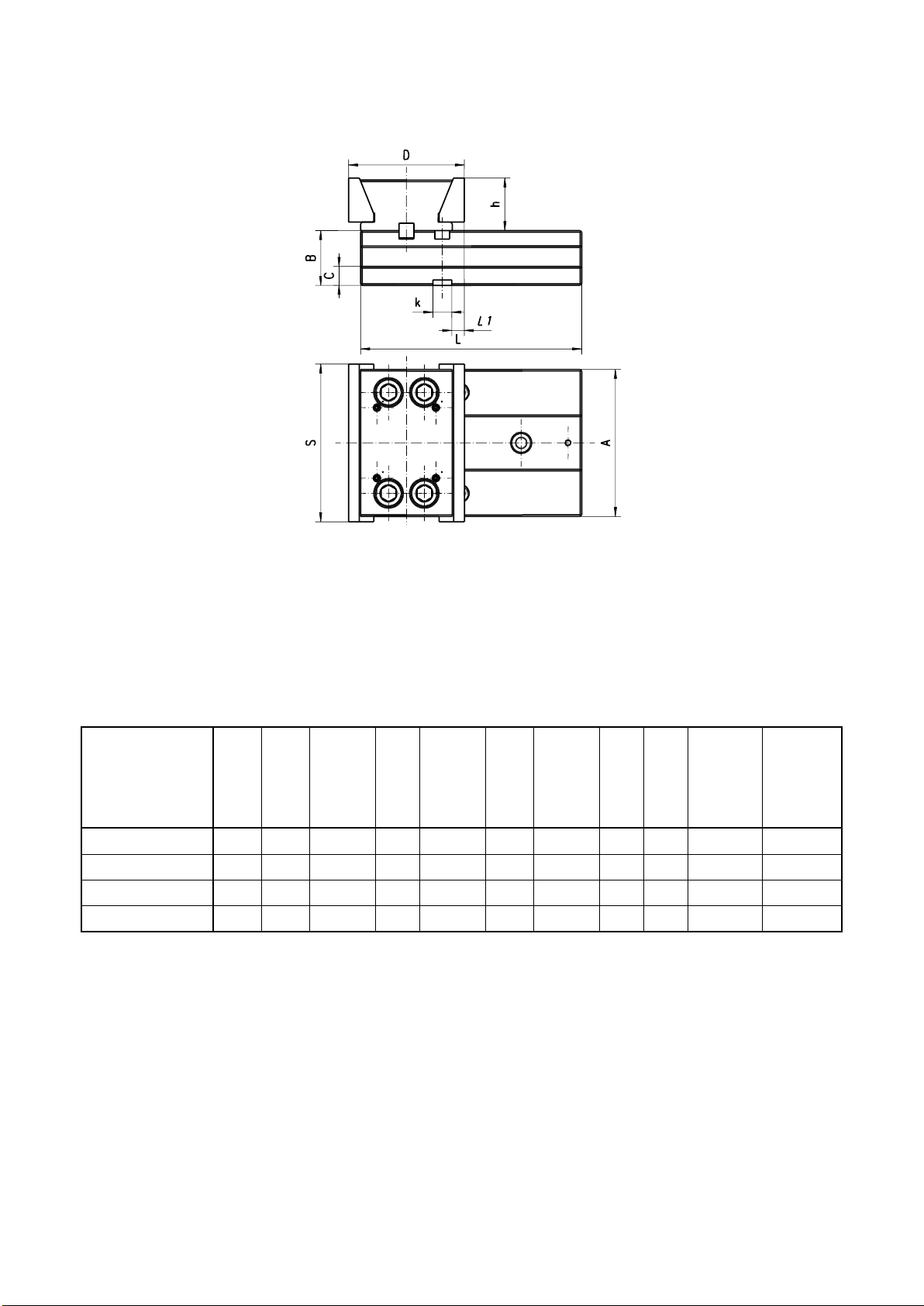
Basic specifications of precision machine vises - type 6620 and 6621 are shown
at Fig. 3 and Table 1.
Fig. 3. Basic dimensions of precision machine vises- type 6620 and 6621.

6
Table 1. Basic specifications of precision machine vises - type 6620 and 6621.
Type
S
A
B
C
H
L1
L2
L3
a
h
k
Max.clamping
force
Weight
-0,02
±0,02
M6
daN
kg
6620-100-320/165
100
85
35
13
65
320
61,8
18
165
30
12
2000
9,84
6620-125-335/165
125
105
42
15
82
335
68
24
165
40
12
3000
15,71
6620-150-425/210
425
210
31,95
6620-150-475/260
150
140
52
18
102
475
87,29
30,2
260
50
18
4100
35,18
6620-150-520/305
520
305
36,96
6620-200-535/260
535
260
58,95
6620-200-585/310
200
165
61
20
121
585
109,43
47,07
310
60
18
4500
61,66
6620-200-635/360
635
360
64,36
NOTE !
Dimension h in 6620 type vises is different then that in vises of 6566; 6567; 6568; 6569-M; 6571 and 6577

7
Basic specifications of precision machine vises - type 6622 and 6623 are shown
at Fig. 4 and Table 2.
Fig. 4. Basic dimensions of precision machine vises - type 6622 and 6623.
Table 2. Basic specifications of precision machine vises - type 6622 i 6623.
Type
S
A
B
-0,02
C
L
a
h
k
M6
Max.clamping
force
[daN]
Weight
[kg]
6622-100
100
85
35
13
140
48
30
12
2000
5,3
6622-125
125
105
42
15
160
60
40
12
3000
8,7
6622-150
150
140
52
18
210
86
50
18
4000
19,1
6622-200
200
165
61
20
240
78
60
18
4500
33,9
8
Basic specifications of precision machine vises - type 6624 are shown at Fig. 5
and Table 3.
Fig. 5. Basic dimensions of precision machine vises- type 6624.
Table 3. Basic specifications of precision machine vises - type 6624.
Type
S
A
B
-0,02
C
D
±0,04
L
L1
±0,02
h
k
M6
Max.
clamp
force
[daN]
Weight
[kg]
6624-100
100
85
35
13
80
155
10
30
12
2000
4,4
6624-125
125
105
42
15
84
160
10
40
12
3000
6,7
6624-150
150
140
52
18
110
210
12
50
18
4000
14,5
6624-200
200
165
61
20
127
240
15,5
60
18
4500
26,5

9
5. OPERATION
5.1. Preparation the vise to operation
After unpacking the vise please:
➢
Check if none of parts is missing,
➢
Remove the preservative from vise surfaces,
➢
The mating surfaces of clamping inserts (4), fixed jaw (2) and movable jaw (3)
should be covered with some grease,
➢
While transporting the vise to machine tool make sure that the holder is
protected against self-tilting by means of the screw (10),
➢
Screw (10) should not be screwed to the vise guides,
➢
Before attempting the operation check the gap width between clamping
inserts and jaws as stated in point 5.5.
5.2. Vise positioning on machine tool
Use the parallel and longitudinal keyways and fixture keys (13) to position the
vise on the machine-tool table.
5.3. Fastening vises on the machine-tool table
Machine vises of 6620 type may be fastened on machine-tool table in
longitudinal and transverse way. The transverse fastening with clamping lugs,
delivered with vises, is able on tables with dimensions as shown in Fig.7 and Table
4. Location of clamping lugs is shown in Fig. 6.
Fig. 6. The way of fastening machine vises of 6620 type on machine-tool table.

10
Fig. 7 shows correct location of the vise on machine-tool table. Only unloaded
part of the vise base may project outside the table (the one beyond the holder).
Cases shown in Fig. 8 are forbidden.
Fig. 7. Correct location of vise on machine-tool table
Table 4. Machine-tool table dimensions
Type
Machine-tool table dimensions
a
t
M
100
12
50; 100
M10x35-10.9
125
12
32; 63
M10x35-10.9
150
18
50; 100
M16x45-10.9
200
18
63; 125
M16x45-10.9
11
Fig. 8. Forbidden location of vise on machine-tool table.
5.4. Changing the opening range
Before changing the opening range clean vise base (1), lead screw (9) and
holder (9). To change the opening range just tilt the holder (8) forward and move it
to engage the proper recess in the base (Fig. 9).
Fig. 9. Changing the opening range
The screw (10) located in holder (8) secures the holder from self-tilting and
accidental movement of whole assembly: holder-lead screw-movable jaw.
Holder (8) must be secured from self-tilting by screwing on the screw (10)
when:
➢
transporting or repositioning the vise on the machine-tool
➢
using the vise in vertical position
The screw (10) should not be screwed to the vise guides.
12
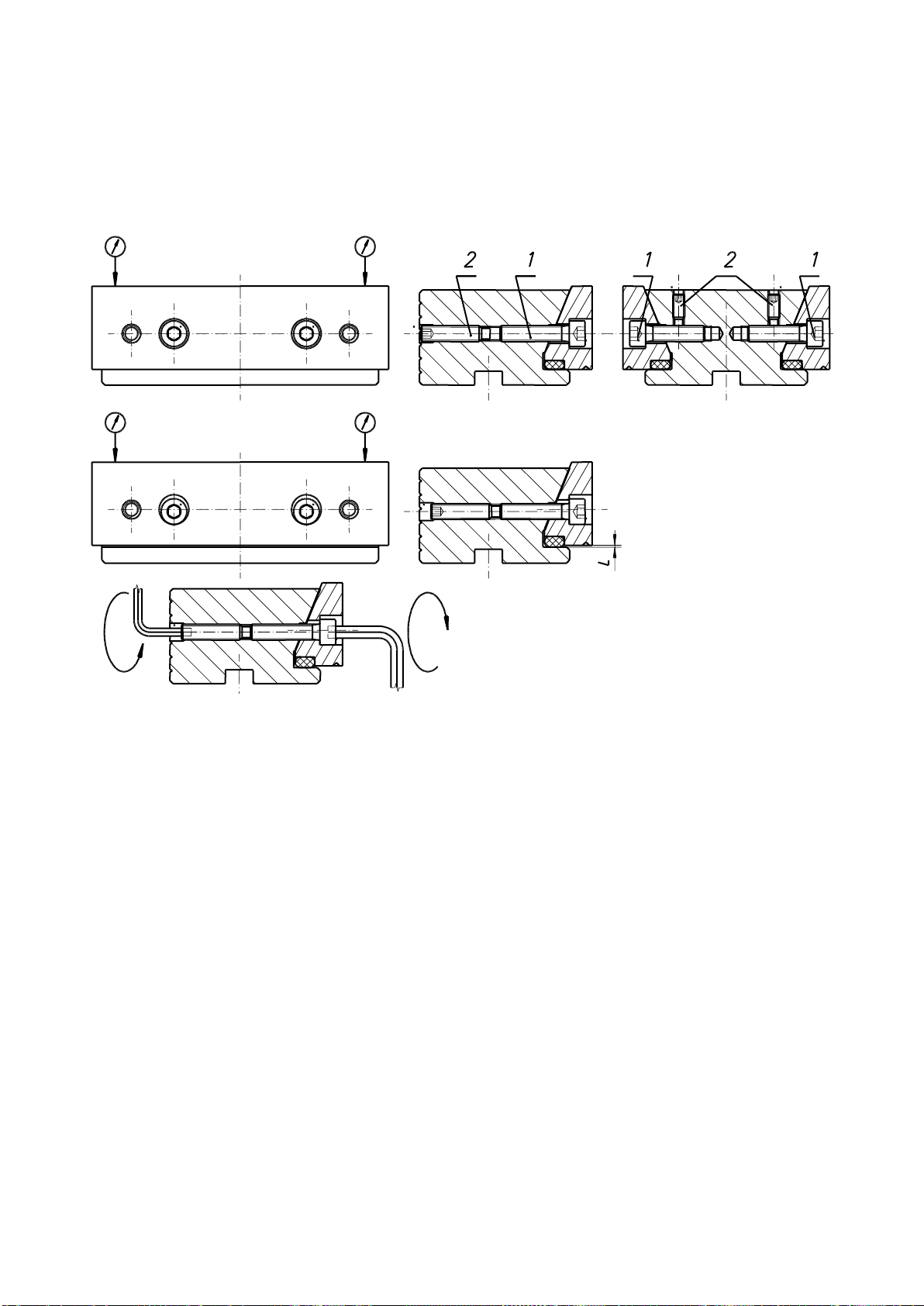
5.5. Clamping the workpieces
Clamping inserts are seated in vise jaws with play ensuring correct clamping
the workpieces. The value of play should be L = 0.2 mm with accuracy of positioning
0.01 mm. The difference between “L” dimensions in movable and fixed jaw should
not exceed 0.01 mm. Accuracy of positioning of clamping insert is shown in Fig. 10.
Fig. 10. Accuracy of positioning of clamping insert.
To obtain the required positioning of clamping insert do as follows:
1. Loosen set screws (2).
2. Tighten the bolts (1) to make the clamping insert seat in jaw guide.
3. Check with dial gauge the parallelism of clamping insert toward the vise
base.
4. By loosing bolts (1) set required value of L = 0.2 (
0.01) mm.
5. Check with dial gauge the parallelism of clamping insert toward the vise
base, parallelism of clamping insert toward the vise base should be the same
as measured in point 3.
6. By tightening set screws (2) secure bolts (1).
Perform above steps for setting clamping inserts both in fixed jaw and movable jaw.
The proper clamping conditions is obtained when clamping inserts seat into jaw
guides. That assures the best clamping accuracy.
13
Each time after end of machining:
➢
clean thoroughly the base guides, clamping inserts, jaws and lead
screw,
➢
pay special attention to clean the gap between clamping inserts and
jaws (L dimension on Fig. 10).
If during the clamping, inserts do not seat on jaw guides:
➢
dismantle clamping inserts,
➢
clean insert surfaces mating the jaws and cover them with some grease
➢
by means of mounting bolts set the correct position of inserts to obtain
the required value of L.
Hammering the clamping inserts or the workpiece, base guides or the
wrench when clamping is forbidden.
Do not lengthen the wrench while clamping.
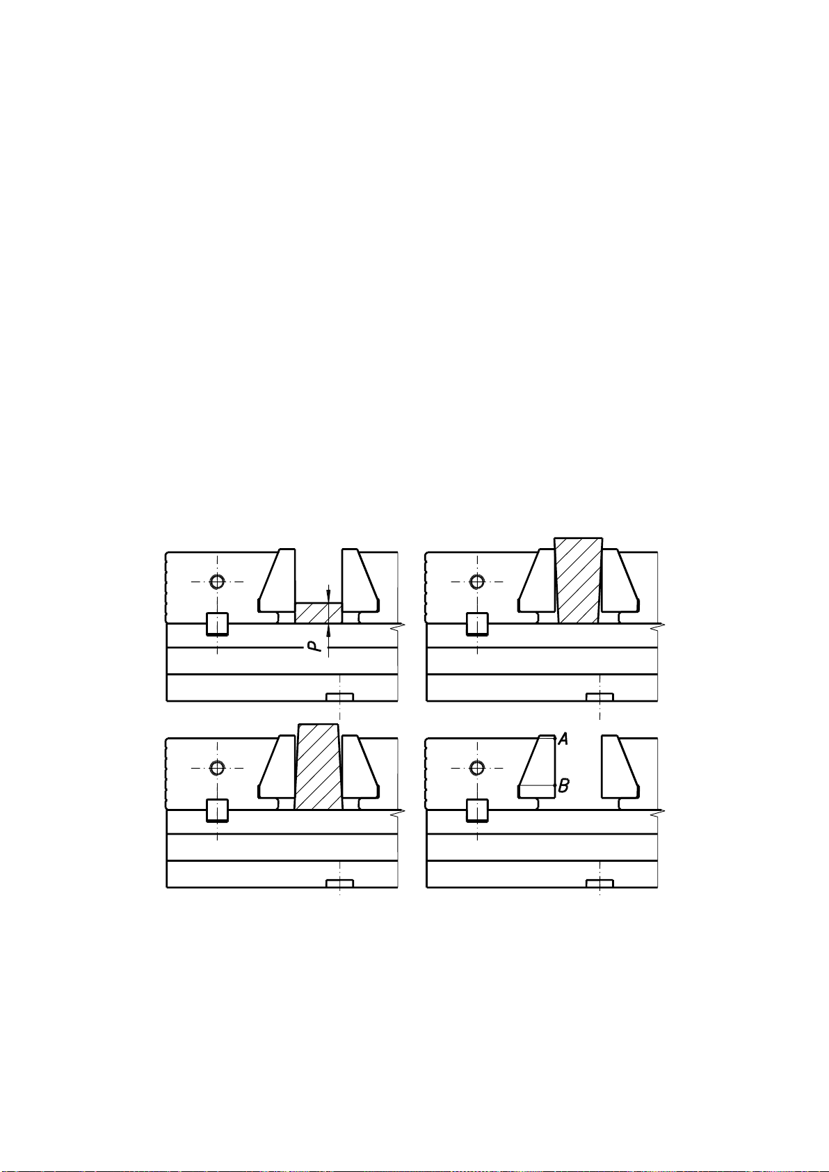
Inadmissible shape, thickness and way of clamping workpieces in vise jaws
presented in Fig. 9 are inadmissible. The workpieces should be clamped at the A-B
section of clamping insert (Fig. 11). The thickness of clamped workpieces (“P”
dimension as in Fig. 11) should not be less then 1/3 h (the “h” values as presented
in Fig. 3).
Fig. 11. Inadmissible shape of workpiece.
14
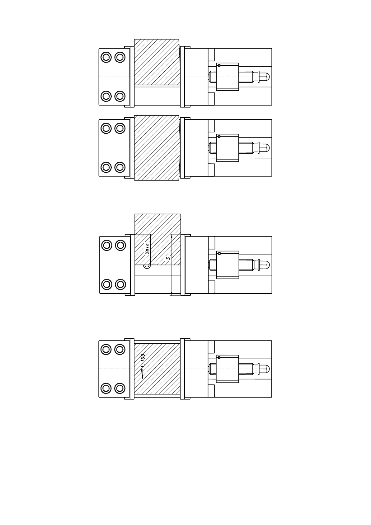
The ways of clamping the workpieces of irregular shapes are shown at Fig. 12,
13 and 14.
Fig.12. The way of clamping the workpiece of irregular shape.
The right effectiveness of clamping is achieved when S
min
>1/2 S.
Fig. 13. The way of clamping the workpiece of irregular shape.
The clamping the workpiece with taper lower then 1:100 may be effective only
when it is clamped at entire length of jaws.
Fig. 14. The way of clamping the workpiece of irregular shape.
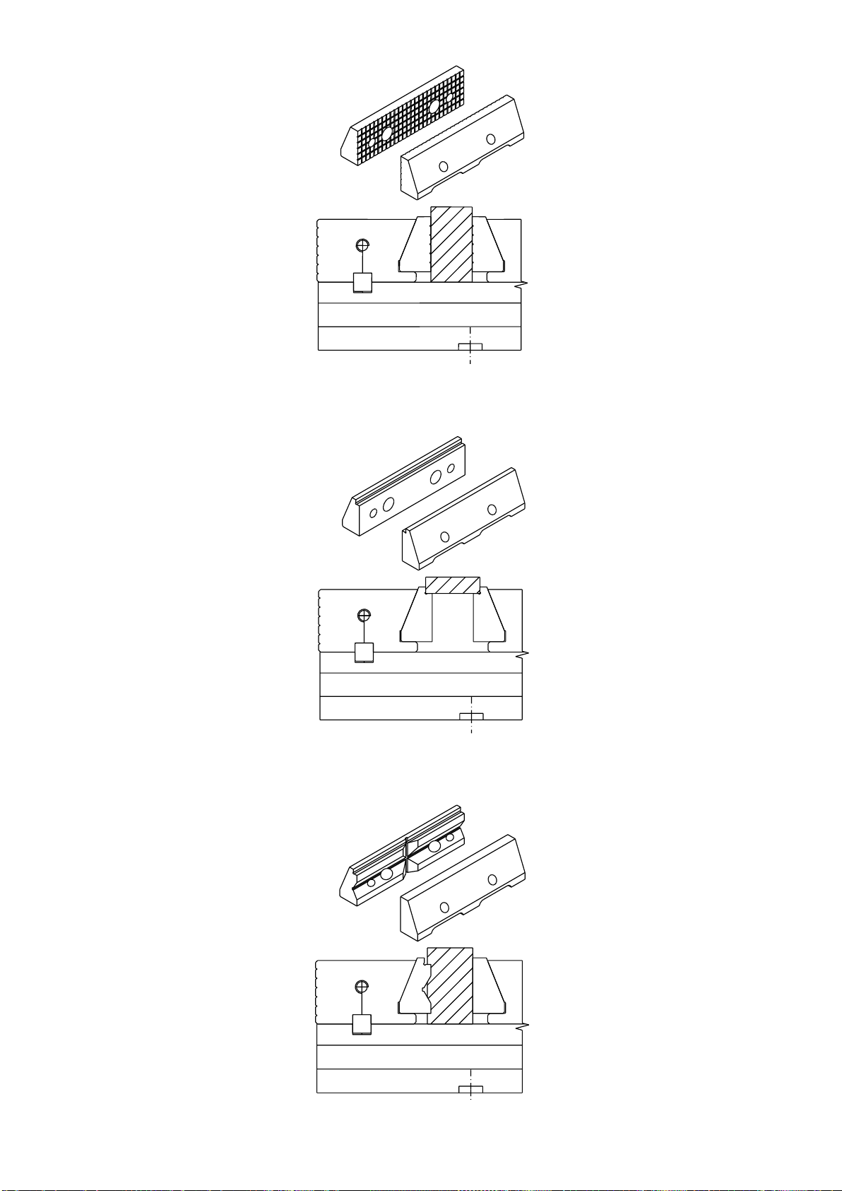
Jaw insert should be mounted on jaw guides when:
➢
Clamping the workpiece with jaw edges
➢
Clamping the workpiece with grooved surface of stationary jaw
➢
Clamping the workpiece with the prismatic or stepped jaw inserts
(Fig. 22, Fig. 23)
➢
Clamping the workpiece with the grooved jaw inserts (Fig. 21),

15
When clamping shafts with the prismatic jaw insert (Fig. 23) the other jaw insert
must have plain surface.
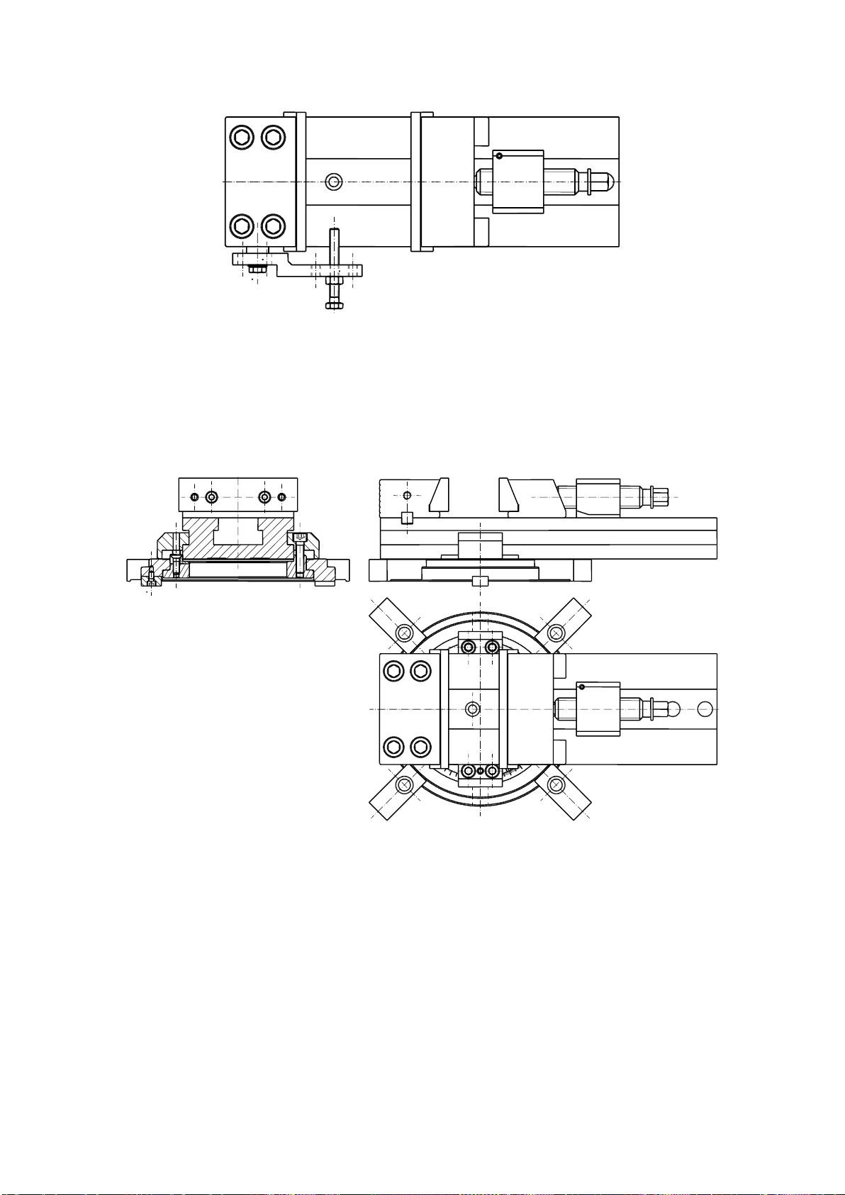
For clamping the workpieces with irregular shapes the swinging leading plate
can be used which allows the movable jaw to swivel by about ± 2°.
Fig. 15. Usage of self-aligning guide plate.
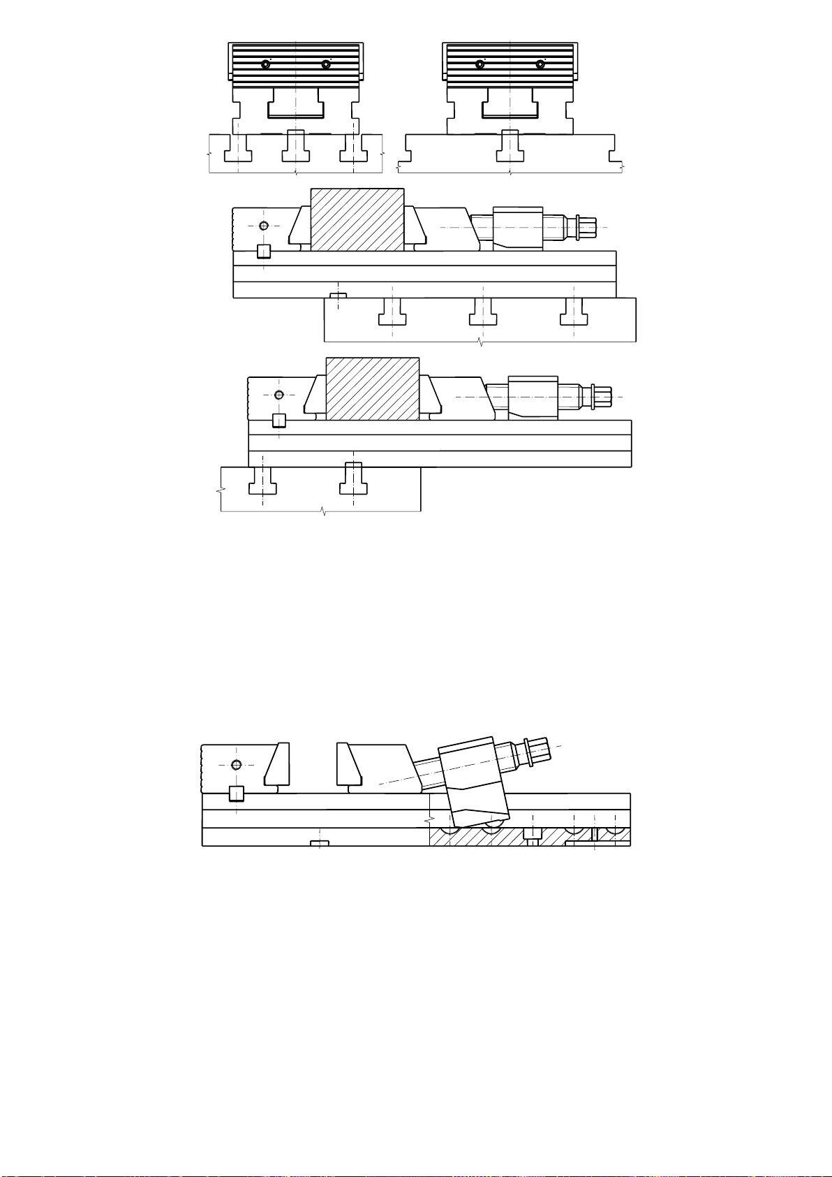
5.6. Using the sets of vises
Precision machine vises may be assembled in machining sets. It enables
machining large workpieces or multi-machining. Examples of clamping positions
with the use of vises of 6620; 6621; 6622; 6623; 6624; 6568; 6569M; 6571; 6577
type are shown in Fig. 17.
Fig. 16. Examples of clamping.
Type
L1
L2
L3
L4
100
0 –43
0 –40
7 –64
50 –107
125
0 –43
0 –50
8 –76
52 –120
150
0 –62
0 –75
12 –106
67 –166
200
0 –57
0 –65
13 –104
75 –166

16
Fig. 17. Examples of clamping positions.
6. ACCESSORIES
6.1. Standard accessories
Standard accessories for the precision vises include:
Item
Type
6620
6621
6622
6623
6624
Wrench
1
–
1
–
–
Clamping lug
6
6
4
4
4
Self-aligning guide plate
1
1
1
1
–
Wrench type 6596
–
1
–
1
–
Fixture key
2
2
2
2
2
Fixture key screws
2
2
2
2
2

17
6.2. Optional accessories
The optional accessories of precision vises include:
➢
Lead screw block - it may be replaced with hydraulic spindle block or may be
a spare part
Fig. 18. Lead screw block.
➢
Hydraulic spindle block - it may be replaced with lead screw block or may be
a spare part
Fig. 19. Hydraulic spindle block.
➢
clamping inserts plain
Fig. 20. Clamping insert - plain.
18
➢grooved jaw insert
Fig. 21. Grooved jaw insert.
➢stepped jaw insert
Fig. 22. Stepped jaw insert.
➢prismatic jaw insert with step
Fig. 23. Prismatic jaw insert with step.
19
➢
side stop of 6597 type - when fastened to the side of fixed jaw enables
positioning of workpieces parallel to inserts surfaces
Fig. 24. Side stop of 6597 type.
➢
swivel base of 6586 type - enables rotating the vise around vertical axis at a
required angle. The base is graduated
90
in 1
increment.
Fig. 25. Swivel base of 6586 type.

20
7. MAINTENANCE
Each time after end of work:
➢
Clean thoroughly the vise.
➢
Dismantle the
clamping inserts.
➢
Clean inserts, jaws and thrust plates.
➢
Cover the surfaces of inserts mating with the jaws with some grease.
➢
By means of mounting bolts set the correct position of inserts to obtain the
required value of L dimension (point 5.5).
➢
Preserve the vise with the anti-corrosive.
8. WORK SAFETY REGULATIONS
➢
Operator must read this instruction before attempting to operation.
➢
In case of abnormal work of spacer or damages, stop the work and inform
supervision staff.
➢
Qualified personnel must perform repairs and overhauls.
➢
Except mentioned above regulations observe your local safety rules.
9. FINAL REMARKS
➢
Following the instructions given in this manual provides long lasting and
trouble-free vice operation.
➢
Failing to do this will void any manufacturer warranties and liability.
Manufacturer reserves the right to make the construction changes without notice
General Terms and Conditions of a Guarantee and Complaint of the
“BISON” S.A. Company Ltd. Products –are given in the
www.store.bison-chuck.com
This manual suits for next models
12
Table of contents
Other Bison Industrial Equipment manuals


