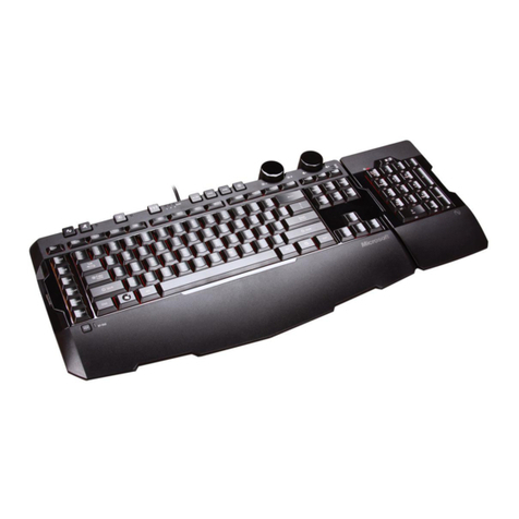
bit MIDI MASTER KEYBOARD User manual

\
MIDI
.
MASTER
KEYBOARD
l
-J
~-~_
.
...;_
__
,
·--~ ~J..>);..=-··-·~~---
_.,;.
~~

CONTENTS
Introduction•••••••••••••··~·············••••••••••••••••••···
KIDI
and
Control
Connections••••••••••••·······•••••••••••••••
The
Back
Panel
••••••••••••••••••••••••••••••···~·············•
Haster Keyboard
Operation,
.the
Display••••••••••••••••••••••••
Progra••ing
Patches•••••••••••••••••••••••••••••••••••••••••••
Da
t
A
Entry ••••••••••..•••••••••..•
, ,
•.•••••••••••••••.••.••.••.•••••.•••
Assigning
Sound
Progr a•s •......•..•.....•••••••....•.•...•.••......
Progra••ing
Spllt9
••••••••••••••••••••••••••••••••••••••••••••
Transpose
Functions•••••••••••••••••••••••••••••••••••••••••••
Tr
011b
1
eshoo
ting
s
Connections
••••
, , , • , ,
•••••
,
,
•••
, • ,
••••
,
, •
,
•••
The
Keyboard
Naps
The
Di
api
ay
•••••
,
,
••••••
,
•••••
,
•••••••••••••
KIDI
CHANNEL
TRS
••••••••••••••••••••••••••••••••••••••••••••••
"JDI
IN
•••••••••.••••••••••.•
•
• •
•
• • • • • •
•
•
•
•
• • •
• • • •
•
• • • • • • • • • • • • •
Sen1itivlty .••.•••••• ••
•
•
••..••
,.
•
,
••..•.•.••••.•.•..•...
.-
..•
~
.
.,.
•...
External
Settings•••••••••••••••••········••••••••••••••••••••
Channel
Assign
to
Controllers
•••••••••••••••••••••••••••••••••
No.
Assign
to Controllers········~··•••••••••··················
Saving
and
Copying Patches
within
He•ory •••••••••••••••••.••••
Exchanging
Patches
within
He•ory ••••••••••••••••••••••••••••••
/
The
Cassette
Interface
•••••••••••••••••••
~
••..••••••••••••••••
Storing
Data
on
Cassette······••••••••••••••••••••············
Verification
of
Data
Transfers••••••••·•·•········••••••••••••
Loading
Data fro•
Cassette···•··········•••••••••••••••••·•···
Troubleshootings
Data
Transfer
••••••••••••••••••••••••••••••••
Connection
of
an
External
Sequencer
•••••••••••••••••••••••••••
The
Sequencer1
Playing
a
Sequence
or
Song
•••••••••••••••······
Sequencer
Control
Buttons•••••••••••••••••••••••••••••••••••••
Recording
Sequencesi
Sequence/Function
Node•••••••••••••••••••
Function
11
Setting
Sequence Para•eters ··········•·•••••••••••
Function
2a
Setting Record
Paraaeters
••••············•••••••••
Function
31
HIDI
Channel OUT••••••••••••••••••••••············
4:
5:
Function
Function
Setting
Run
Node
Para•eter•··••••••••••••••••••••••
Copying
Tr1:ck1
••.•..•.••
•.•
••••••••••••.•...••..•..•
Deleting within
a
.Track,
••
,
••••••
,
• , • ,
,
, ,
, ,
, •
,
••
,
••
Hhing
Tracks
Function
Function
Function
l:t'
7:
a:
.,
~
.
Erasing
Sequences ••••••••••••••••••••••••••••••••.
Fune
t
ion
91
Cop yin
g
Sequences ••••••••••••••••.••
,
••••••••••.
,
••
Function
Os
Chaining
Sequence•••••••••••••••••••••••••••••••••
Function
100:
Progra•
Change/OMNI
coa•ands
•••.••••••••••••••••
Song Node
e
.•
t
I-
._
• • I-• •
•.
• • t
.•
• •
.•
• • a• ••a
s • •
• a•
s
11
• •
e •
• •
e
•
41
t
e
I • • •
a
•
•
•
Ill
Inserting
and
Deleting
Sequences···········••••••••••••·······
Appendix
A1
Appendix
e:
Appendix
Ca
Patch
Map
Display
"essages ••••••••••••••••••••··············
HIDI
Exclusive
Codes•••••••···········••••••••••••
He•ory
Transfers~·····•·••••••••················••
• •
• •
•
•
•
•
•
• •
• •
•
• • • • • •
• •
•
• •
•
•
• • • • • •
•
• • • •
•
•
• •
•
by
Abi
B•••••nn
and
"ichel
Isler
Version
1.0,
Karch
1986
(C>
Copyright
1986
by
BIT
1
1-60022
Castelfidardo/Italy
3
5
6
8
9
10
11
12
14
15
-16
17
17
19
21
22
23
25
26
27
28
28
29
30
30
32
33
35
37
38
39
40
41
42
42
43
43
44
44
45
46
47
49
50
51
All
rights
reserved.
All
r•production
by
any
•eans,
in
whole
or
ln
part,
only
with
prior
written authorization
of
the
publish•r.
2

Congratulations
on
your
ne•
BIT
NASTER
KEYBDARD!
Your
choice
of
this
fine
instru•ent
clearly
shows
that
you
have
read the
Nriting
on
the
"all
(spelling
•NIDI•>,
and
that you have
a
fair
idea
of
state-of-the-
art
•usical
instru•ents
and
their
i•plications/applications.
All
the
sa•e,
we
strongly advise-you
to
read this
Users
Nanual
carefully
so
that
you
can
take
full
advantage
of
the
advanced features
the
BIT
nASTER
KEYBOARD
hag
to
offer.
Any
instru•ent equipped
Nith
as
•any
features
as
the
BIT
NASTER
KEYBDARD,
and
dealing
with
a
subject
as
co•pleK
as
NID]
aight
create
a
bit
of
initial
confusion
for
the
new
user.
To
help
avoid
this,
the
•anual
introduces
each
feature
in
turn
and
allows
•hands
on•
learning.
If
you work
through
the
instructions
step-by-step,
you
should
have
a
pretty
good
grasp
of
how
things
work
by
the ti•e you reach the
last
page.
Along
the way
we'll
be
pointing
out
so•e
potential
problea
areas
concerning
'slaves'
or
the
NASTER KEYBOARD
itself
and
-
of
course
providing
hints
on
hoN
to
circuavent
the•.
In
fact,
quite
a
bit
of
nIDI
proble•
solving
is
built right
into
the
instruaent's
hard
and
softNare.
Whenever
the
BIT
NASTER KEYBOARD
recognizes
a
proble•,
the
display
will
show you
an
error
code.
(A
co•plete
listing
of
these
codes
Î9
included
in
an
Appendix
at
the
back
of
this
•anual).
For the sake
of
clarity,
we
won't
elaborate
on
NJDI
ter•inology
in
the
•ain
text,
so
if
you're unfa•ili&r
with such
esoteric goodies
as •ALL
ONNI
Off•
and
other
NIDI
co•••nds,
you •ight find
it
hRlpful
to
consult
a
general
teKt
on
"IDI,
or
at
least
broNse through
the
glossary
to
catch
up
with
soae
of
the
jargon.
Ne
took
great
care
in
writing
thi•
here
•anual
(instead
of
lying
on
the
beach
and
watching
the
-
er -
waves,
which
we
•ould
have
preferred).
If
anything
has
sneaked
in
that
leaves
you
absolutely
confused,
we'd
like
to
knoN about
it,
so we
can
correct
it in
future
versions
and
updates!
lf
you have any
suggestions
for
i•prove•ents,
additions, deletions, fancy
applications
or
weirdly-wonderful
uses
of
this
instru•ent
that
even
we
didn't
think
of,
don't
hesitate
to drop
us a
line
and
tell us
all
about
it.
(Please!)
Other
users
•ight
just
love
you
for
il!
Have you
filled
out
your
warranty registration
card yet?
If
not,
you
should
do
so,
have
your
dealer
sta•p
it
and
•ail
it
presto.·
.•
3
...

NARNINI
HON
NOT
TD
ENDAN8ER YOURSELF
OR THE
NABTER
KEYBOARD••••
Ne
are
convinced
that
you've
read
thit
a
aillion ti•es
before,
but
before
you
plug
in
your
new
in1tru•ent,
do
check
the
label
•t
the back
to
•ake
sure
that
the
unit
is
•et
to
the~orrect
line voltage.
The
BIT
NASTER
KEYBOARD
has
been
designed
and
•anufactured
with
great
care,
to
assure
your
safety.
l•proper
u1e
can
result
in
potential
electric
shock
or
fire
hazards.
You
too can
do
your
part,
never
use
any
electrical instru•ent
in
extreae huaidity
·
or
•hen
wet!
All
functions
are
accessible
fro•
the
outside;
there
are
no
user
servicable
parts
inside.
Refer
all
servicing
to
authorized
personnel.
Any
unauthorized
ta•pering
will
void
your
warranty!
Bee
the
warranty
card
for
•ore
detaîled
infor•ation.
SPECIAL
NOTE1
EXTERNAL
SEQUENCER
CONNECTION
We
can
fully
understand
-
and
sy•pathize
-
if
you have itchy
fingers
and
Nant to
start
exploring
your
new
keyboard
right
aw1y.
Well,
DON'T!
We
1ugge1t
you read
a
little
further
first.
Nhile
you
can't
actually
daaage
the
internal
circuits
if an
external
sequencer
or
co•puter
is
hooked
up
wrongly,
you can
still
cause
havoc!
So
it
is
vital
to
read
the
special
section
•External
Sequencer
Connection•
BEFDRE
plugging
in
an
external
sequencer
unit!
4

NlDI
AND
CONTROL
CONNECTlONB
OU'I
•••
,....
îN'f/f,Mlt;-,
MDI
~
MD,01tY
,-- CTll.---.
"1\l'OI
a
@@QQ@@@@@@-:@@©3
,
STOi"
SYNC
8YNC roar
FOOT
.
IN
OUT
IN
'IHRU
OUT
I
OUI'
2
~ IUI
IN
OUT
OH
Off
,uw._
SWltt:H
swm:H
The
BIT
NASTER
KEYBOARD
is
-
as
its
name
suggests
-
the
control center
for
your
entire
MIDI
universe.
It
lets
you
control
synthesizers,
dru•
~achines, expanders, computers, effects
and
Khat-have-you.
It
also
brings
a
great
tidying effect
to
any
stage
setup:
this
one
key~oard
is
all
you
will
ever
need
on
stage.
The
rest
of
the
MIDI
units
(the
ones
Nhich
actually
produce
the
sounds)
can
be
stashed
away
so1eNhere
out
of
sight,
quietly
and
efficiently
controlled
by
the
"ASTER
KEYBOARD,
all
linked
si~ply
by
MIDI
cables
(standard
5pin
DIN
cablel,
And
Nhile
Ne're making
life
si•pler,
why
stop
at
clearing
the
jungle
of
cables
from
your
stage
set-up:
when
we
say
it
was
designed
as
the
'heart'
(and
brain!>
of
your
MIDI
syste•,
we
really
mean
it!
The
HASTER
KEYBOARD
lets
you
change
Sound
Progra•s
and
control
features
such
as
Split
Point
or
Pitch
Transpose
plus
loads
of
other
synthesizer
control
infor1ation
(like
Key
Velocity
and
After Touch
values,
Release
Pedal
or
Modulation
Bend
info,
to
naMe
just
a
few}.
What's
the
big deal?
Well,
Nhile changing
settings
on
a
host
of
keyboards
without rushing
all
over
the
stage
Might
save
energy,
there
is
far
more
to
the
BIT
"ASTER
KEYBOARD
than
that!
Like
no
•ore
racking
your
brains
trying
to
reMember
all
the
coaplex codes
to
run
your MIDI
set-up
in
hectic
situations.
Just
take
a
few
quiet
Mo•ents
at
hoae
to
put the
relevant
info
into
the
memory
banks
and let
the
BIT
"ASTER
KEYBDARD
take
the heat!
There
are
b4
'Patches·
to
hold your
pre-set
data, and
reproduce
it
at
the
flick
of
a
switch. Saves your
nerves
in
rehearsal
rooDs
and
at
live
gigs; and
just think
of
the
ti•e
you'll
save
in
the
studio
••••
where,
as
Ne
all
know,
ti•e
equals 1oney
1
~oney,
money!
NIDl control
flow
1nd
c1bl111 th1
b11ic1
HIDl
instru1ents
are
plugged
into
one
of
the
KASTER
KEYBOARD's
NlDJ-
Out
connectors,
using
a
standard
5pin
DIN
cable
connected
to
the
NIDI-
In
socket
of
the
NJDJ
instru•ent.
If
your
set-up
includes •ore
than
two
MlDI
units,
MIDI-Thru
of
the
first
instrument
in
each
chain
is
connected
to
MIDI-In
of
the
neKt
instrument,
HIDI-Thru
of
that
instrument
is
connected
to
MIDI-In
of
the
next unit
and
so
on.
You
needn't-
Horry
about
following
any
particular sequence
when
connecting
instruments:
as
you
will
see
later
on
in
this
manual,
NIDI
provides
a
•eans
of
properly identifying
and
addressing
instru1ents
hooked
up
anyNhere
in
the chain,
regardless
of
their
position.
(NDTEs
If
you
have any
trouble getting
the
NASTER
KEYBOARD
to
'play'
your
other
units
when
first
setting
up,
check out
the section
on
•HJDl
CHANNEL
1ns•
on
Page
17},
5pin
DIN
cables
of
various lengths
are
readily
available
at
your
local
music
store
or
radio
dealer.
Although
current
MIDI
standards
suggest
a
uxillu•
cable
length
of
15
meters
I
approx
•.
50ft),
we
strong}
y
reco~&end
not
exceeding
5
meters
(approx.
15ft)
in
cable
length
to
ensure
trouble-free
operation.
5

NHAT
YOU'LL
FIND
ON
THE
BACK
PANEL
••••
Nh•t,
no
1udio
?!?
That's
right
-
strange
though
it
•ight
see•
-
there
•re
no
audio
connections
to
•ake: the
NASTER KEYBOARD
doe•
not
generate
any
sound
itself.
Instead,
it
sends
"JDI
infor1ation
(dat1)
to
the
connected
units,
Nhich
in
turn
Nill
use
this
MIDl
data
to
play notes
and
change
progra•
settings,
to
start/stop
in
the
case
of
sequencers
and
dru•
eachines
and
to
perfor•
various •housekeeping•
tasks
etc.
If
you
have
a
nice
large
MIDI setup
with
•any instru1ents
1
you
should
try
to
avoid
connecting
~ore
than
four MIDI
units
in
series
(what
they
call
a
•daisy-chain•
configuration: hooking
up
NIDI-Out
on
the
"ASTER
KEYBOARD
to
MIDI-In
on
the
first unit,
patching
its
HlDI-Thru
to
HIOI-
In of
the
next
instru1ent
etc.
as
described
above).
BlT
MIDI
circuitry
is
of
high
quality
and
uses
extreaely
fast
co1ponents.
HoNever
1
depending
on
the
quality
and
speed
of
certain electronic co•ponent1
used
by
other
~anufacturers
for
their
instruments"
NIDl
circuitry
(Optocouplers,
for
any
electronics
freaks
out
there),
s•all
ti•e
delays
could
occur,
and
these might
•ccumulate
to
cause
an
audible
delay
as NIDI
data
is
passed through
a
chain
of
instru1ents.
An
elegant
and
tidy
way
of
co•ing
to
grips with large
setups
is to
use
one
or
several
"HIDI
Thru-Boxes"
{a.k.a.
•NIDI
Split
Box•
or
•NJDJ
Parallel
Box•),
a
number
of
Nhich
are
co••ercially
available,
NlDl-ln
and
NIDJ-Thru
on
a
NASTER
KEYBOARD?
Yes,
sur•!
You
•ight have
wondered
why
the
NA&TER
KEYBOARD
is
equipped
with
a
NIDI-In
connector, There
are tHo
good
reason1i
firstly,
the
keyboard
is
designed
so
that
it
can
be
•played•
(or
ratherz
controlled)
by
a
re1ote
keyboard.
The
second reason
is,
that
the
NA&TER KEVBOARD"s
built-in
aicroprocessors
are
capable
of
filtering
and/or
otherwise
•odifying
HIDI
data
input
fro•
a
co1puter
or
sequencer
for
advance4
operation.
This
•custo1ized•
NIDI
datai,
then available
at
the
HIDI-
Out
connectors,
Nhereas
the
unaltered
data
is
always
routed
to
the
MlDI-Thru
connector.
But
•ore
about this later
•••
You
1i9ht ••nt
to
u11
p1d•l•,
too
•••
The
CONTROL/PEDAL
socket
on
the
back
panel
lets
you
connect
a
volu•e
pedal.
Internal
circuitry
translates
pedal
action
into NIDI
data,
"hich
can
then
be
assigned
to
a
nu1ber
of
different functions
(such
as
Vibrato
or
Volu1e
etc.)
1
depending
on
the
particular
capabilities
of
your
HIDI
instru1ents.
The
FOOT
SWITCH
socket
is
used
to
connect
(surprise!) foot
s"itches
1
such as
a
sustain
foot switch,
Another
pedal
you
1ight find
useful
with
your
NASTER
KEYBOARD
is
the
PATCH ADVANCE
pedal. Just
tap
your foot
to
step
through chains
of
progra•st
without
ever
taking
your
fingers
off
the
keyboard.
6

Did
"e
say you
need never
take
your
fingers
off
the
keyboard?
Quite
right!
You
can
plug
a
foot
pedal
into
the
RUN
socket,
and
use
it
to
start
a
sequence
stored
in
the
internal
sequencer.
A
pedal
linked
to
the
STOP/CONTINUE
socket
lets
you
stop
a
sequence
in
1id-flight,
and
restart
it
fro•
the
sa•e
position
later
on.
The
C"ultl)-Tape
Connection
What we
have here
are t"o
sockets
that
serve
several purposes.
For
one,
you can
save
and
load
Patches
(settings
fro•
the
HASTER
KEYBOARD's progra~
ae1ory)
to
and
fro•
a
cassette
tape.
They
are
also
used
to
save
and
load
Sequences
(i,e,
your
personal
sy1~honies
co1posed
with
or
stored
in
the
built-in
sequencer),
Yet
another
option:
these
very sa•e
connectors
let
you
synchronize
the
built-in
sequencer
with
a
multitrack
aachine
1
using
a
FSK-signal.
That's
what
they ~ean when
they
say
1ulti-purpose!
·And yes,
we'll
be
telling
you
all
about these "onderful things
a
bit later,
too,
But
let's
look
at
a
couple
•ore
feature5
on
the
back
panel
first.
Synchroni11tion
it
th1 n1•1
of
th•
a•••···
Making
sure
the BlT
NASTER
KEYBOARD
stays
in
sync with
e~ternal
sequencers
or
dru•
~achines
is
easy
with
·clock
pulses
trans•itted
via
the
SYNC-JN
and
SYNC-OUT
sockets,
and
avoids
such
disasters
as
the
dru~
beat
running
away fro•
the
rest
of
the
band!
Though
technology
hasn't found
a
way
of
hooking
real
live
drum•ers
into
"IOI
yet
•••
Play it H.hl
You can't
always
stop
curious people
fro•
pressing
buttons
on
your
precious
hardNare
(known
as
the
nose-pressed-on-the-Ferrari-window
syndro•e,
or
eat
your
heart
out
•••
>,
but you
can
stop
the•
froa
creating
a
Mess
with your
patches
and
sequences:~hroN
the
HEMORY
PROTECT
switch
at
the
back
to
the
ON
position,
·and
there's
no
way
anybody
can
change
any
of
your
stored
settings!
It's
always
a
good
idea
to
play
it
safe,
and
keep
the
switch
in
the
ON
position unless
you
actually
Nant
to
change
or
progra•
soaething.
NEMORY
PROTECT
doesn't
affect
cassette
interface operation
or
the
loading
of
data
by
aeans
of
a
MIDI
dump:
patches
and/or
sequencer
•e1ory
can
be
loaded
regardless
of
the
switch's
setting.
Hitting
th1t
perf1ct
b••t
••••
The
KETRDNDNE
OUT
socket
lets
you
send
a
signal
fro•
the
integrated
•etrono•e
speaker
to an
external
~mplifier
or
•ixer, when
the
sound
of
this built
in
'pace•aker'
goes
under
in
the
sy1phony
you're
creating!
Now
that
you'v•
r11d
111
this•••
7

BIT
NABTER KEYBOARD
OPERATION
B•tting in qur
••
11',n:e
•
'l
~
-
.-yl...1 ." 'lv-\.'11'.&"y:;i-~\.':.•.
~u"'trns \,\
•u1'Uü,
""l}lL .•
'l~v;.'J'IUt,'i.-
H,.,;.91;.~
1
!l!!!!.
set
the•
to
receive
on
the
NIDl
channel
of
your
choice,
and
.!!!.!ï..
then
poNer
the
NASTER
KEYBOARD
up,
Why?
When
first
s"itched
on (and
also
Nhen
a
new Patch
i5
called
up),
~he
NASTER
KEYBOARD
5ends
out
data
to
all
your
slaved
HIDl
units
-
so
any
not
switched
on
will
•iss
out
on
this
infor1ation!
The
last
active Patch
will
auto1atically
be
recalled
(i.e.
the
one you
were
using
when
you
turned
the
power
off),
_.....,. o,---ot---01
....,._ ----o•--o•-o•
en."""
••.
----o
1
---0 I ---o I
••••.••••••.
----0111-011-olt
a...
---_-01'---oM-o•
-
,
o•
...,
••....
•...... ..•...
0 OO 0 0 0
0 0 0 0 0 D 0 DODOO 0
.......•._
•.••
,
'"""°'t
ftOI .,.,04
1
2
1
4
5
100
0 0 0 0
._..
+
...
0 0 0 D 0 O. 0 DODOO D 0
-
•••••
...,,,,
---
.•..
•
1
I t
0
{ I
KEYBOAAD
....,.
..•
ClflON ••. l[T1-
,.,
_.._
...
1,-
1t
-
•.
,
...
12-
•••
12
MDI-
•.
,-
13--
--
0< ..- to CO<TllOl.lPlll
14
•••••••
--
23
••••••
-
1s-- - N
c;,.,-.....,.
•.
,
•..
li
••••••
10Ul>I
--
:!5.,..._
26
Cl"-
WHll(IL
...
~-
21
JITN'"
lllDl..04
17
wt•
...
,
•.
,e
....,
•
..
,_
•••
-.,i;,c:ornu.LPI
28
CJOL---
...
~
-y n
CJOL
-
19-
...
30
CJOL-
....
20
••••
"'°'
•..
l'l•flll~
~-
--
""-
0 0 0 0
..
~.
0 0 0 0 ~
--
·-
b1911T
- -
••••••
-
---
After
turning
the
po"er
on
1
th1
NASTER
KEYBOARD
"ill
briefly
flash
•ee·ee·ee•
in
the
LED
display.
This
•ark,
the
initialization
of
the
aicroprocessors,
and
at
the
same
ti•e
gives
you
a
visual
check
that
all
LED
5eg•ents
are
Norking.
The
display
will
then
change
to
whatever
it
Nas
showing
when the
power was
last
turned
off,
giving
you
an
overview
of
the
status
of
various
para1eters.
Depending
on
the
current
•ode
-
shown
by
the
LEDs above
the
SCROLL
buttons
<HIDI
CHannel,
PR06RAH
1
SPLIT,
TRANSPOSE)
1
different
LEDs
in
the
LED
Matrix
(upper
part
of
the
display)
will light.
With the
LED
lit
for
KBO
MAP,
some
LEDs
in
the
Hatrix •ight
blink.
Don't
worry:
that's
just fine.
~e'll
be
explaining
the
mysteries
of
all
these
glowing
lights
as we
coae
to
the
functions
they show,
Just
a
bit
further
on
•••
After
that
quick
overview
of
the
display, let's
•ove
on
to
pressing
so•~ buttons!
8

As
we
~entioned
a
bit
earlier, you
can
control
a
huge nuGber
of
NIDI
devices
"ith
the
NASTER
KEYBOARD,
But
let's
not
go
overboard
to
start
off
Nith: for
siaplicity's
sake
Me'll
assu•e
that
you'll
be
working
with
three
MIDI
synthesizers
or
expanders
(Ne"ll call the•
MIDI
units),
a)l
of
Nhich
are
capable
of
supporting
the
NIDI
ONNION
and
ONNI
OFF
•odes.
If
in
doubt
about
which aodes
your
instruments
can
handle
1
check
out
their
Users
Manuals
and
look
for
the
•NIDI
I~plementation•
section,
which should
provide
you
with
the
neccessary
inforaation.
If
you
can't see•
to
locate
it,
y-u
should
consult
your
friendly
dealer.
Dur
first
"101
Ch1nnel
Patch
Right
then, let's
get
started.
We'll
begin
by
progra~1ing
what
is
known
as
a
MIDI
Channel
Patch
-
sounds
sophisticated
already,
but
don't
panic,
it's going
to
be
painless
••••
and
I
knoM
that's
what
the
dentist
always
said, but
this ti•e
it's
true,
pro•ise!
While
the
confusing
range
of
words
comaonly
used
to
describe
the
'sets'
of
data
stored
in
synthesizers,
expanders,
sequencers
etc.
is
more
or
less
freely interchangeable,
we're going
to be
using
the
Mord
'P~tch'
when
referring
to
the
infor•ation
stored
in
the
NASTER
KEYBOARD's
•e•ory;
this lets
us
save
the
Nord 'Prograe'
to
describe
voice
data
in
other
NIDI
units
-
Nhich
ought
to
cut
down
on
the
confusion!
A
MIDI
Channel
Patch
lets
you
divide
the
keyboard
into
three
zones.
Each
of
the
zones
can
span
Ntiatever
key
range
you like,
and
the
three
ranges
can
even
-0verlap.
Vou can
send
data
for
each
zone
(keystrokes,
progra• change
etc.
etc.I out
on
a
different
MIDI
channel,
so
that
three
MIDI
units
can
be
played
completely
independently.
ln
that case,
of
course
1
the
NlDI
units
•ust
previously
have been
set
to
receive
on
the
selected
NIDI
channels.
9

,
Thlt
it
ho•
d1t1
1ntry
Nork,,
The
LED
for
HIDl
CH
should
be
lit,
shoNing
that
the
keyboard
is
in
HIDI
CHANNEL
•ode.
If
it
isn•t,
you
have
to
press
a
•scROtL•
button
(possibly
several
li•e5)
until
lt
co••s
.on.
By
turning
to
MIDI
CH
aode
1
you
have
at
the
sa•e ti1e
changed
all
the
other
displays
to
shoN
you
infor•ation
pertaining
to
"IOI
channels.
That's
how
the
MASTER
KEYBOARD NOrkss
it
alNays
di•play•
the
setting•
for
the
current
aode,
indicated
by
the
LEDs
in
the labels
above
the SCROLL
buttons,
LEFT RIGHT
PATCH
CENTER
ADDRESS MIDI CH.
KBD MAP
e
VALUE
BB BB BB BB
The
nuMeric
LED
displays
shoN four
one
or
two-digit
nuabers.
The
right•ost display
shows
the
HIOI
Patch
Nu•ber.
There
are
64 MIDI
Channel
Patches
(nu•bered
1-64)
at
your
disposal.
So
let's
go
ahead
and
progra•
Patch
nu•ber
1:
press
the
Nhite
key
under
the
rightaost
display
(the
PATCH
LED
should
noN
co•e
on).
NoN
you
can
enter
the
Patch
nu~ber
u&ing
the
nuaeric
keypad.
Note
that
when
entering
one-
digit
nu•bers
you
NUST
type
a
leading
zero,
though
the
zero
Hill
not
appear
in
the
display.
Alternatively,
you can use
the+/-
keys
to
step
the
nu•ber
in
the
display
up
or
doNn.
Whichever
you
choose,
the
display
should now
shoN
•1•.
Don't
touch
the
Nhite
key
under
the
right1ost
display
again
for
the
•o•ent,
If
you
Nere
to
change
the
NIDI
Patch
Nu•ber
at
this
point
in
ti~e,
all
the values
previously
prograamed
for
this
patch
Nill
be
restored,
and
all
the
ne"
infor•ation
entered
for
the
MIDI
Channel
Patch
"ill
be
lost,
si~ply
because
the
"ASTER
KEYBOARD
would
assu•e
that
you
Nanted
to
start
progra••ing
a
different
MIDI Channel
Patch.
Pressing
the
•EXT.
SET" or
•JAPE•
buttons
has
the
same
effect.
Only
after
entering
all
neccessary
data
for
this
new
Channel Patch
Nill
you
tell
the
NASTER
KEYBOARD
to
store
it
into permanent
1e1ory.
,For
details
see
under
SAVING,
COPYING
AND
EXCHAN6IN6
P~TCHES,
Page
28),
NeKt
you'll instruct
the
NASTER
KEYBOARD
to
use
certain
HIDI
channels
for
the
different
zones.
The
channels
progra••ed
for
each
zone
are
shoNn
in
the
three
LED
displays
to
the
left
of
the
PATCH
display.
If
t"o
horizontal
lines
are
shoNn
in
any
of
the5e
displays,
that
zone
is
inactive
and
cannot
be
program•ed.
(We'll be
giving
details
on
hoN
to
activate
zones
and
assign the~
to
the
keyboard
in
the
SPLIT
section
on
Page
12
beloN).
10

You
have
16
MIDI
channels
to
choose
fro•
(values
1
-
16>,
but
let's
use
MIDI
channels
2
1
4
and
6
for
the left,
center
and
right zone
respectively.
Press
the
white
key
under
the
leftaost
display
<LEFT
ZONE),
Now
enter
the
NIDI
channel number
for
that
zone
(•02•>,
again
using either
the
nu•eric
p~d
or
the+/-
keys.
Don't forget
to
punch
in
the
leading
zero
if
you're
using
the
keypad.
Next,
press
the key under
the
second
display
from
the
left (CENTER
ZONE)
and
enter
HID!
channel
number
•04•,
Now
press
the key
under
the
third
display
from the
left
(RIGHT
ZONE>
and
enter
its
HIDI
channel
n~mber
•06".
You
have
now
instructed
the
HASTER
KEYBOARD
to
send NIDI data
for
the
three
zones
to
separate
(individual>
HIDI
channels. Nhat
you
haven't
progra1Med
yet
is
the
sound
program
numbers
for the
receiving
MIDI units,
or
a
~ey
range
for
each
of
the
zones,
10
no" for
a
look
at
that.
ABSIBNINB
SOUND
PRDBRAHS
LEFT
RIGHT
PATCH
CENTER
ADDRESS MIDI CH.
M3=J••~M#)
VALUE
88 88 88 88
This
part
of
the
BIT
NASTER
KEYBOARD
Patch assigns
a
SOUND
PRDGRAN
nu~ber
to be
transmitted
to
each NIDI
unit,
to
select
a
specific sound
fro•
the
program •e•ory
of
the
receiving
synthesizer,
First select
P~OGRAM
mode,
by
pressing
the
SCROLL
button
until the
PROGRAM
LED
is lit.
The
display
will
now
shoN
which
sound
progra~s
are
active
for
each
active
zone
in
this Patch
("1"
in
our
exa•ple).
Using
the
nu~eric
pad
or
the+/-
button
enter
the
progra•
numbers
(fro~
1
120)
for
each
zone
(as
before,
first
selecting
the
current
zone using
the
white
button),
~OTE:
to
enter
nu•bers
over
100
1
first
press
the
100
button
and
then
enter
the
other
figures
e.g.
125
=
100,
2
1
5.
The
display
Nill
show
a
dot
in
the
upper
left
hand
corner
next
to
the
25
(•'25•):
..
11

PRDBRANKJN&
SPLITS
Dividing
the
keyboard
you'll
have
encountered
the
BIT
"ASTER
KEYBOARD
extended
~pportunities
sounds!
into
separate
zones
or
splits
is
so•ething
before,
what 1ight
~e
neN
-
and
exciting
-
in
is
having
three
zones
to
play
with,
plus
the
offered
by
overlapping
zones
and
double
LEFT
CENTER
RIGHT
PATCH
ADDRESS MIDI CH.
.
KBD MAP
e
VALUE
BB
BB
BB BB
Ne'll
start
with
a
si•ple
split
Nith
three
zones:
first
put
the
"ASTER
KEYBOARD
into
Split Mode
by
pressing
the
SCROLL button
until the
SPLIT
LED
lights.
The
LED
displays
noH
show
the
pre-progra••ed
split
data
-
don't
worry
if
there
are·
letters
in
the
CENTER
LED,
Ne'll
be
explaining
that
in
just
a
•o•ent.
You
enter
the
Split
Point
like
PRDSRA"
or
MIDI
data,
first pressing
the
Hhite
button
to
select
the
zone
and entering
the key
nu•ber
(counting fro•
the
left
on
the
keyboard), using
the
nu•eric pad
or
the+/-
buttons.
To
save
you the
chore
of
counting
keys,
the
BIT
NASTER
KEYBOARD
Nill
also
let
you
enter
the
Split
Point
by
hitting
the
note
you
Nant
on
the
keyboard, Nhile pressing
and
holding
the
Nhite zone
button.
The
nu•eric
value
for
the key
chosen
as
Split Point
will
then
be shown
in
the
display.
So,
to
program
our
straightforNard
three zone split
first
press
and
hold
·
the
white
button
under
the
LEFT
ZONE·
display
and
play
•c3•
(the
third
C
fro~
the
botto•>
on
the
keyboard.
The
display
will
shoN
•25•,
telling
you
that
your first
split
point
is
set
to
the
25th
key.
FolloN
the
sa~e
procedure
for
the
RIGHT
ZONE,
this
ti•e
playing
·c~·
on
the
keyboard.
The
display
will
confirG
with
•49•,
shoNing
the
second
split
point set
to
the
49th
key. (The
defined
Split
Points
are the
last
note
in
the
LEFT
ZONE,
and
the
first note
of
the
RIGHT
ZONE>.
But·
Nhat
about
the
center
zone,
you
ask7
A
glance
at
the
display
will
find
two
'brackets',
shoHing
that
the
center zone
has
been
defined
auto•atically
by
setting
the
left
and
right
zone5. You can
check
this
out
by
playing
a
few
notes
in
each zonez you'll
find
each
instrument
responds according
to
the
zone/channel
number assigned.
Before
Ne go
on to
a
more
complicated
Split
we
should
mention
that
each
zone
can
be
transposed
individually, details
in
the
TRANSPOSE
section
below!
12

OVERLAPPJNB
ZONES
AND
DOUBLE SOUNDS
As
Ne
said, you can
define
your
split point
.so as to
create
overlapping
zones
or
double
sounds.
If
you
reverse
the
settings
in
the
above
exa~ple,
allocating
split point
•49•
to
the
LEFT ZONE
and
split
point
•25•
to
the
RIGHT
ZONE,
you
get
'an
overlap
in
the
center
zone.
This
appejrs
in the
CENTER
ZONE
display
as
"LC",
showing
that
the
center zone has
been
assigned
to
the
left
zone,
But
what does
this
all
mean?
Well, the
easiest
way
of
understanding
it
is
to go
ahead
and
play!
Playing
at
the
botto~
of
the
keyboard
you
have
the
instru•ents
assigned
lo
both LEFT
and
CENTER
ZONES,
moving upward
past
•c3•
(or
k~~,
2~l.lhQse_in
the
RIGHT
ZONE
join
in,
while
above
•c5•
(k~y
491
only
those assigned
to
the
RIGHT
ZONE
are heard.
It
isn't
as
co~plicated
as
it
might
look
here
-
try
it
out!
Of
course,
that
is
just
a
single
exa•ple.
Instead
of
assigning
the
CENTER
ZONE
to
the
LEFT
ZONE,
you
can
link
it
with
the
RIGHT
ZONE;
or
even
disable
it
entirely,
<by
pressing
the
"hite button
under
CENTER
ZONE,
then
using
the+/-
button
to
select
"re•
or
"ne•
respectively!.
To
disable
the
LEFT
or
RIGHT
ZONE
press
the
white button
and
enter
the
value
•o•
using
the
nu•eric
pad.
So
program•ing
overlapping
split zones
gives
us
double
and
split
settings
si•ultaneously;
for
'pure'
double
sounds
set
the
split
point
for
the
LEFT ZONE
to
the
highest
note
(by
pressing
that
key
or
entering
the
value
•72•1
and the
RI6HT
ZONE
to
the
lowest note
(value
"1~1.
The
CENTER
ZONE
can
be
ignored
her~
{or
disabled
if
you
prefer
-
set
value
to
•ne">,
because
the
left
and
right zones are
spread
over
the
whole keyboard.
Another
way
of
progra•ming
double
or
•ultiple
sounds
is
to
use
the
"OMNl•
setting,
described below
under
Paraaeter
(211.
•..
SOME SPLIT EXAMPLES
·
,,
,
)
H
ff
In
H.ff
I
um
H
ff
I
ff,
ï
m
,
n m
m
f
l
L;T
CE=TER Rl~HT
A
•
B
•
c
.
:3L L-'
'-19
25
49
'- _,
A
c
-n
2
='
n
c:
-, IÏ
:Ju
29
A 49. C
L,r, o
t:
'
_J
ïC
c
:J
25
•
13

.•
TRANSPOSE
FUNCTIONS
Flexibility
is
the
na~e
of
the
gaee here
too:
you'll
find
the
•GENERAL
TRANSPOSE•
s"itch
(lower
right corner
of
the
Keyboard Table
on
the
front
panel) useful
for
standardized
pitch
adjust~ents.
It
lets
you
tran~pose
the
pitch
of
the
Nhole
keyboard
do"n
by
one
or
tNo
octaves.
Hore
sophisticated de~ands
are
met
using
the
TRANSPOSE
function,
which
alloNs individual
adjust•ent
of
pitch
in
se•i-tone
steps
for
each
of
your
prograaaed
Split
Zones.
If
you
tried
our
earlier
exa•ple
for
progra••ing
Split
Zones
INith
Split
Points
set
to C3
and
C5>,
you
probably
found
chords
played
in
the
left
zone
sounded
too
low.
Ne
can now use the
TRANSPOSE
f~nction
to
fiK
that.
<TRANSPOSE
Nill
also take
care
of
any
NIDI
units
that
1ight
have
been
playing
in
the
wrong
key
so
far!)
LEFT
RIGHT
PATCH
CENTER
VALUE
ADDRESS
.,
KBD. MAP·
e
MIDI CH.
88 88 88 88
You
should
have
the
general
idea
behind
setting
these
parameters
by
now,
and
this
is
no
eKceptionJ first
go
into
TRANSPOSE
iode
by
pressing
the
•scROLL•
key until the
•TRANSPOSE•
LED
co•es
on,
Select
the
zone
you
want
to
transpose
by
pressing
the
white
key
under
the
appropriate
display, which
will
show
the
current
value
of
the
lowest
note
jn
the zone.
Then
enter
a
new
value:
either
by
typing
the
key
number
on
the
numeric
pad,
using
the
+/-buttons,
or
by
playing
the
note
you
want
on
the
keyboard
while
holding
the
white button
doNn~
In
our
example
after
selecting
LEFT
ZONE,
the
display
will
show
•1•
<which
tells
you
that
the
current
value
for
C1
1
the
loNest
key
in
this
zone,
is
set
to
•1•
-
the
first
key
on
the
keyboard,
or
botto•
Cl.
You
can
then
trans~ose
to
a
aore
har1onious
pitch!
The
TRANSPOSE
function
will
also
operate
in
overlapping
Split Zones
-
clever,
isn't
it?
TRANSPOSE EXAMPLE
1-- - --- -- ------- --- -- - - --- ---- ------ - ------72
IH
''
n
I
H
''HI B
1,"
m
1'
''
IH
1'
n
1,
f
I
Hf
I
1
1
I
lg7
)32
~
J
I
I
')(....
<,
•.
I I
/ "' '/
I
I
./ ',,...._
//'-........_,
I
I
/
.....
/
•........
I
I
/
.
/ <,
/
.....
/
••...
I
r
'--...
/
-....
...
I
l i
CENTER
RIGHT
LEFT
CENTER
RIGHT
I
I
]2
-
27
"
14

s.
If
you are
noK
reaching
the
point
of
tearing
your
hair,
climbing
Halls
or
throKing yourself
and/or
the BIT
"ASTER KEYBOARD
out
of
nearest window
because
nothing
Norks
•••
don't despair, help
is
hand!
the
the
at
The
following
section
on
the
KEYBOARD
HAP
will
take care
of
proble•s
originating
in
disabled
(turned
off)
NIDI
channels,
but
first
a
few
hints
of
things
to
check
before
going
co•pletely
crazy.
(He
knoN that
•ost
of
this stuff
sounds
hopelessly
basic
and
i•possible
to
forget,
but
don't think
"e're
insulting
your
intellect:
you'd
be
amazed
to
hear
how
many
people
trek
all
the
way
to
the
store
to
complain
and
then
discover
that
they
never
got
round
to
plugging
the
•achine·
in!)
The
check-list
only
takes
a
couple
of
minutes,
but 1ay
save
you
hours
•••
I
Are
all
units
connected
to
the
power
supply
and
turned
on?
I
Are
all
connections
'clean':
check
cables/jacks/sockets.
I
Are
HID!
units hooked
up
in
the
right
way?
(NASTER
KEYBOARD
NIDI
OUT
to
MIDI
IN on
unit
lJ
MIDI
THRU
on
unit
1
to
NIDI
IN
on
unit
2
etc.)
I
Are the
NIDI
units
set
to
the
correct
RECEIVE
CHANNEL
-
i.e.
the
same
MIDI
channel
you
prograamed
in
the
NASTER
KEYBOARD
Patch?
Everything
OK so
far?
The
HIDI
CH
TRS
section
of
the
KEYBOARD
NAP
•hich follows
contains
•ore hints
on
troubleshooting
for
those
of
you
Nho're
still
stuck with
obstinately
silent
instruments;
plus info
and
guidelines
on
how
to
aake these
features
work
for
you instead,,,
e,
15

THE
KEYBOARD
"AP
Those
fa~iliar
•scRDLL•
buttons
will
st,p
you through
to
KEYBOARD
"AP
•ode
1 shown
by
the
KBD
HAP
LED
-
along
"tth
a
veritable Chri,t•as
tree
of
LEDs
above
the
display.
The
aap and
~atrix
provide
infor~ation
on
the
status
of
various
paraaeters
1
as
they
are
shown
in
the
Keyboard
Table
on
the
front
panel.
·
SEQUENCER
OR:.
....
0
OO
0 0 0
0 0 0 0 0 0
o.,ttt lrilll19()t( ~ ,
Y..-c:'11
I
'fUCll
I ,a.o
4
+
0 0 0 0
0 0 0 0 0 D
..
_
-
_
..
••••••
/Cll:»f1.
011
r--------=- --------,
I
1t
Y90AAO
I
I
~.. un-...,,-
I
10
~
a,wr,ee.
,...
21
OWN
•·~
J
Il
OIH
11111,1"
22
f'lllCll*.W....
••••
I
12
"'°'
_..,
llllln7't
13
MG\. liai. _,.,,,
°'
AS901.
TO
CQN111CU.Ol!S
I
14
Ml.(..
'11'to.
23
'"CIH
.,._ .-
,
cw
f
ts-~owm ~
21111ci-..,oor~ ••
,....
I
1. Mmt 'DOI
i;-.,.,.
25
Clll..
'ffiM. ~,cw
2'
Cl' IMC8. •••,..
I
I
17..,.,
•.
,..
11
18
our
:z
_.,..
ftilo.
~ m
CCJrrrilTM:i&.LOS
I
I
JO
cr..._....
••••
l
31
,,
.••.•
...,.
,..,..,..
::--:=
I
~-:
I
D r1
I
a.,
.~
,11,
.•
,
~
I
- -
-
-
---
L- - - --- - ----- - J
_....,.. ·-01---0i--OI
•••••••
- ----0
4
---0 I ---0 I
CJlll.l'tJl,I M.----o I ---0 I ---0 I
cm...-
----O'G---011--ollt
.,,.
•.•••.
----o a---o
1•
---o'"
llllÏl9I>-,
.......,
~----'
-
-
-
-
ZJ
,,,......
'°'"°'
15
16
~
:::cJ--C:I
lllHCI H _.,
.•. .•.
0 0
0 0 0 0
...•.
0 DODOO 0
oc.a,.
1.
2
3
•
5
,OO
+
0 DODOO 0 0
..•.
I
1
•
t
0
c
•
·-
20--
...
00 0 0
0 00
The
display
sho"s
the
current
Patch
number
(rightaost
LED>;
the
address
nuaber
currently
accessed
(LEFT
LED>;
the
current value
of
the
para~eter
(RIGHT
LED>;
MIDI
CHANNEL
infor•ation
(where
relevant>
is
shown
in
the
CENTER
LED
and
the
numbered
LEDs
in
the
•atrix.
The
first
ti•e
you
enter KBD MAP •ode after
poHering
the
"ASTER
KEYBOARD
up
will
autoMatically
access
ADDRESS
•11•
1 MIDI
CHANNEL
TRS.
(If
you
have
already
used
KDD
HAP
mode, and
another
address,
the
HASTER
KEYBOARD
will
return
to
the
last
address
accessed
instead),
We're
going
to
deal
with
para•eters
•17•
and
"19"
1
shoNing
which
HIDI
channels
are
active
in
the
current
Patch,
first.
LEFT
l-..1
CENTER
W
RIGHT
,----,
PATCH
____..
I
---,
ADDRESS
H
MIDI CH.
1-i
VALUE
I
I
,
I
n
YI
I I I
u
16
KBD MAP
O

~
'
:
..
~i~~~-!·
·~
:
·
..
~-}~~-~-
\g,-1~-·-i
"IDI
CHANNEL
TRB
MIDI CHANNELS TRS
17
OUT
1
ON/OFF
18
OUT
2
ON/OFF
I
HIDI
OUT
I
(17)
•
NIDl
DUT
2
(18)
The
light-show generated
by
this
paraaeter
is
not
just
a
pretty
effect:
the
blinking
LEDs
in
the
•atrix
show
at
a
glance
which.
MIDI
channels
are
active
in
the
current
patch.
lin
case you
hadn't
guessed,
the
blinking
ones
are
•oN•
and
the
dark ones
"OFF").
When
the
NASTER
KEYBOARD
leaves
the
factory,
all
HIDI
channels
are
active
and
routed
to
both
HIDI
OUTs,
so
that
at
parameterl
(17)
L
(18) all
LEDs
in
the
~atrix
should
blink.
If
they
don't,
it's
a
si~ple aatter
to
activate
them
yourself,
and
1ight
also
explain
any
trouble
you had Mith
'deaf
and
du~b'
HlDl
units!
Activating
'silent'
MIDI
channels
works
on
the
exact
sa•e
lines we've
used
so
far:
access
KBD MAP
aode
(using •SCROLL•
buttons>;
then
select
ADDRESS
•17"
(press
the
left~ost white
button,
enter
•t7"
using
numeric
pad
or+/-
keysl.
Check
the
Ratrix
LEDs
for
inactive
channels;
select
the
appropriate
MIDI
CHANNEL
(by
pressing
NIDI
CH
Nhite button,
then
entering
channel
nuRber
using
nu~eric
pad or+/-
keys); the
VALUE
display
will
sho"
the
current value
for
this channel
("O•
=
OFF1
"t•
=
ONI.
This
can
now
be
changed
(again
using
either
numeric
pad
or
+/-
keys).
The
matrix
LED
will
i~~ediately
change
to
shoK
the
new
status.
Paraaeters
•17•
and
•1aN
"ork
in
exactly
the
saae
way,
so
those
with
NIDI
units
hooked
up
to
both
HIDJ
OUT
1
and
MIDI
OUT
2
should
check
out
both
para~eters!
NOTE:
when
controlling
a
large
MIDI
set-up,
it
•akes
good
sense
to
send
data
out
over
both
HIDI OUT
connections.
HIDI THRU
circuitry
~ight
be
incredibly
fast, but
you
can
save
up to
501.
trans•ission
ti~e
in
this
way.
HlDI
IN
MIDI
IN
10 RECEIVE CHANNEL
1
+16
-
11
OMNI
Gl/OFF
-
12
PITCH BEND ON/OFF
-
13
WHEEL MOD. ON/OFF
-
14
RELEASE ON/OFF
-
15
PROGRAM CHANGE ON/OFF
-
16
AFTER TOUCH ON/OFF
17

As we
said
in
the
Intro,
you can hook
up
another
KIDI
source
to
the
BIT
"ASTER
KEYBOARD,
be it
a
re1ote keyboard
or
a
sequencer
or
co•puter,
(But
in
the
latter
case please check
out
the
special
section
•EXTERNAL SEQUENCER CONNECTION•
beforehand).
Input
fro~
another
instrueent
can
be
processed
in
I
variety
of
Nays,
you
may
Nant
to
ignore
or
'filter
out'
certain
co••ands
while
passing
others
on.
The
features
in
this
part
of
the
KEYBOARD
MAP are
standard
MIDI
control
parameters
1
so
those
of
you
fa•iliar
Nith
HIDI
instru~ents
can
skip
this
section!
They
are
entered
and
stored
in
Patches
just
like
the
data
"e've
dealt "ith
so
far.
To
program
para~eters
governing
HIDI
IN
put the
KASTER
KEYBOARD
in
KBD
"AP
eode
(as
usual,
using
the
•scROLL"
buttons>;
choose
the
address
for the
para1eter
you
want
to
change
(pressing
the
white
button
under
the
ADDRESS
LED,
then
~ntering
the
paraêeter
nu~ber). Enter
the
appropriate
value
(pressing
the
"bite
button
under
the •vALUEu
LED,
then
enter
the
value
using
the
numeric
pad
or
+/-
buttons).
The HIDI
CH
LED
is
inactive
and will
show
two
horizontal
lines
during these
operations.
MIDI
IN
MIDI
OUT
1
MIDI
OUT 2
I
I
I
I
I
T
FILTER
MIDI
CH: OUTS
I
..,_
CONTROL
-
SEO.
T ~·
MIX
i.-
...••.
I
r I
I
I
I
I I
I
I
r
r
I
I
I
'
I
I
I I
I
I
I
I
I
RECEIVE
CHANNEL
(10)
If
you have
programaed
a
•o".value
in
the
DHNI
MODE (Para1eter
111,
i.e.
OMNI
OFF,
you can
now
deter•ine
"hîch
of
the
incoming
HlDI
channels
1
-
ib
contains
control
data
for
the BIT
NASTER
KEYBOARD.
The
source
instrument
must
obviously transmit
the
data
over the
appropriate
channel,
for
the
nASTER
KEYBOARD
to
act
on
it!
I
D"NI (11)
.•
Here
you can
choose
whether
or
not the
BIT
KASTER KEYBOARD
should
respond
to all
incoming
MIDI
control data
(OMNI ON,
value
w1•1
1
regardless
of
which
channelJ
or
only
process
data fro• one
particular
channel
(DMNl
OFF,
value
•0•1,
that
you
previously
selected
in
para•eter
(10)
•
18

,
.
.;,,_
•
PITCH
BEND
<12)
This
para1eter determines
"hether
pitch
bend
infor•ation
fro•
the
source
instrument
will
be
processed
t•t•)
or
ignored c•o•1
by
the
MASTER
KEYBDARD.
When the
value
•1• is
set,
data
of
pitch
wheel
gove•ent
~n
the
trans~itting
instru•ent
"ill
be
passed
on
by
the
HASTER
KEYBOARD,
changing
the
pitch
of
notes played
by
the
receiving
instru•ent.
.
I
NHEEL "ODULATIDN
(13)
The
sa-e
applies
to
»odulation
Nheel
infor1ation1
the
BIT
·"ASTER
KEYBOARD
will
pass
on
the
infor~ation
when
this
parameter
is
set
to
•1n
1
and
ignore
it
if
the
value
is
set
to
•o•.
I
RELEASE
<141
Here
you can
select
whether
release
pedal
infor•ation
fro•
the
source
instrument
should
be
passed
on
by
the
"ASTER
KEYBOARD
t•1•1
or
ignored
t•o•1.
I
PR06RAt1
CHANGE
(15)
Vou
want the
NASTER KEYBOARD
to
pass
on
prograa
changes originating
in
the
source
instrument?
Set
this
value
to
a1";
if
you'd
rather ignore
the
data
enter
•o•.
I
AFTER
TOUCH
<16)
And
the
same
goes
for
After
Touch
info
-
AJ•
to
pass
it
on,
•o•
to
ignore
it!
•.
BENS
lT l
Y
lTY
We
have
to
start
by
pointing
out
that
only
synthe§izers
that
already
are
velocity
and/or after
touch
sensitive
will be
able
to
process
such
data from
your
"ASTER
KEYBOARD.
MIDI
syste~s
aanage
to do
a
lot, but
•iracles
are
still
out
of
reach!
A
synthesizer
without
touch
sensitivity
can
receive
such
MIDI
data,
but
will
si~ply
ignore
it
while
cheerfully
acting
on
the
rest.
Ho~ever,
the
"ASTER KEYBOARD
co~es
equipped
with
a
special
feature
which
lets
you
convert
After
Touch
information
to
other for•ats,
such
as
Pitch
Bend
or
Wheel
Modulation.
But
·again:
more about
this
later,
Unlike
~any
synthesizers,
the
BIT
t1ASTER
KEYBOARD
utilises
the
full
dynamic
range
provided
under
NID!
specifications
(i.e,
0 •••
127)
1
so
you'll
find
that
synthesizers
with
a
limited dynanic
range cone
alive
when
'fed'
with
such
rich
fare!
This however,
~ay
prove
to
be
too Duch
of a
good
thing
for
units
not
nor~ally utilizing
the
full
dynamic
range.
so,e
synthesizers,
Yamaha<TH)'s
X-range
in
particular,
will
begin
to
'distort'
sounds
Nhen
receiving
data
"ith
a
high
dynaaic
value.
Parameter
(19)
below allows
you
to
'co•press'
this range
to
fit
your
receiving
unit's
require•ents.
SENSITIVITY
19
DYNAMIC
1
+
16
.•
20
AFTER TOUCH
0+6
19

I
DYNANIC
(19)
Here
you
can store
16
different dynamics
value
for
each
Patch
of
the
MASTER
KEYBOARD.
N.B.
The
values
that
go
from
1
to
8
transmitt
the
full
dynamic
range
provided
under
MIDI specification
(
i.e.
o
...
127).
The
values
that
go
from c1·to
c8
instead,
transmitt
the
dynamic
range
from
Oto
102.
All the
value
are
entered
in
the
usual
fashion:
select
Patch
number;
enter
VALUE
by
pressing
the
white button
and
using
numeric
All the
values
are
entered
in
the
usual
faschion:
select
Patch
~umber;
in
KBD
MAP
mode select
parameter
DYNAMIC
(19)
in
the
ADDRESS
field;
enter
VALUE
by
pressing
the
white
button
and
using
numeric
pad+:-
keys.
Sound too
complicated?
A
few
examples ought
to
clear
that
up:
if
you
set
this
parameter
(19)
to
a
value
of
11
1
11
,
key
veloci:y
variations
are
practically
eliminated
from
the
data
transmitted
to
your
slaves. The
beginners
among
you
should stick
to
the
lower
values,
where
any
irregularities
in
playing
technique
are
smoothed
out,
and thus not
so
obvious.
Values around
"c3"
or
"c4
11
are
best suited
for
the
aforementioned
Yamaha
(TM)
ranges,
and will
avoid
excessively
blaring
trumpets dor
example! All the
expert's
fine
nuances
of
style
-
from
feather-light touch
to
ultra-ffff
- will
be
heard
to
full
advantage
at
the
high
values,
I
AFTER
TOUCH
(20)
You
have
the
option
of
disabling
the
After Touch
Ca.k.a
After
Pressure}
feature
entirely
(by
programming
a
"o•
value). With
After
Touch
active
1
six
steps
of
sensitivity
are
available
here
1
not
to
change
the
'feel'
of
the
keyboard
itself,
but
allowing
yo~
to
determine
how
sensitive
the
keyboard
should
be
to
pressure
applied
after
you
first
hit the
key
-
After
Touch.
Activating
After
Touch
for
single
SpJit Zones
or
programming
After
Touch
ON/OFF
for
single
MIDI
channels
is
dealt
with later under
parameter
(27);
and
converting
After
Touch
infor~ation
into
other data
suitable
for
non-Touch sensitive synthesizers
under
para~eter
(31),
20
Table of contents
