bitubo KIT137A User manual

C.D.A. BITUBO s.n.c. – Via A. Volta,24 – 35037 Z.I. Teolo (PD) ITALY – Tel. (+39) 049-990.34.75
Fax (+39) 049-990.34.47 – Cod Fisc. e Part. IVA 02007650282 – E-mail: bitubo@bitubo.com - Internet: http://www.bitubo.com
N. DI MATRICOLA / SERIAL N.
KIT 137
DA INDICARE IN CASO DI RECLAMO/
TO BE MENTIONATED IN CASE OF CLAIM
KIT AMMORTIZZATORE STERZO
BITUBO usa e raccomanda lubrificanti – BITUBO uses and recommends lubricants
Le immagini e le indicazioni riportate sono a titolo indicativo; C.d.a. Bitubo si riserva la facoltà apportare qualsiasi modifica o variazione senza
alcun preavviso.
Pictures and notes reported are purely as an indications; C.d.a. Bitubo reserves the faculty to make any modification or changes.
Tutte le operazioni di smontaggio e
montaggio contenute in questo manuale
devono essere effettuate esclusivamente in
una officina specializzata.
Bitubo non potrà essere responsabile di
danni al prodotto o alle persone, in caso le
istruzioni contenute in questo manuale non
vengano seguite esattamente.
All the installation and dismantling
operations contained in this manual must be
carried out strictly in a specialised
workshop.
Bitubo cannot be held responsible for
damage to the product or to persons, if the
instructions in this manual are not observed
to the letter.

C.D.A. BITUBO s.n.c. – Via A. Volta,24 – 35037 Z.I. Teolo (PD) ITALY – Tel. (+39) 049-990.34.75
Fax (+39) 049-990.34.47 – Cod Fisc. e Part. IVA 02007650282 – E-mail: bitubo@bitubo.com - Internet: http://www.bitubo.com
Codice: KIT137A_
Marca: DUCATI
Modello: 848
Anni: 2008-2009
MATERIALE CONTENUTO NEL KIT
-n° 1 Ammortizzatore di sterzo corsa 60mm + attacco corpo
-n° 1 Attacco a collare Ø53 L.35
-n° 1 Staffa sterzo (blocchetto accensione)
-n° 2 Distanziali riduttori a diam. 8mm
-n° 1 Vite M8x30 in Ergal
-n° 1 Vite M8x20 in Ergal
-n° 2 Vite M6 femmina
-n° 1 Rondella
-n° 1 Distanziale Ø8 H.10
-n° 2 O-Ring 112 Øi9.92 x Ø2.62
ISTRUZIONI DI MONTAGGIO
Per lo smontaggio e il rimontaggio dei particolari della moto sottoindicati, attenersi alla
procedura descritta sul Manuale Tecnico del veicolo.
1. Togliere la copertura del blocchetto di accensione.
2. Inserire i distanziali riduttori nei fori di fissaggio della copertura del blocchetto accensione in modo da ridurre il diametro a
8mm vedi (foto1)
3. Riposizionare la copertura del blocchetto accensione, e posizionare la staffa di sterzo fissandola con le N°2 viti M6
femmina fornite nel kit (vedi foto 4)
4. Fissare l’attacco del corpo ammortizzatore sulla staffa di sterzo con la vite M8x20, inserendola dall’alto nello snodo
dell’ammortizzatore (foto 1), interponendo la rondella e l’O-Ring (foto 2), e serrando infine la vite a 12.3 Nm
5. Posizionare l’attacco a collare sulla testa di forcella SX, e la camma con il foro filettato rivolta verso il posteriore, in asse
con il senso di marcia (foto 4 ).
6. Inserire l’ammortizzatore di sterzo nel suo attacco, posizionandolo alla misura riportata in foto 3, e poi fissare la testina
dello stelo interponendo il distanziale Ø8 H.10 (foto 4 ; 5; 6) fissando il tutto con la vite M8x30 a 12.3 Nm. Fissare infine la
vite a brugola dell’attacco corpo ammortizzatore, serrandola a 7 Nm.
7. Effettuare alcune sterzate complete a destra e a sinistra assicurandosi che si raggiungano i fine corsa sul telaio della
moto senza sollecitare a finecorsa l’ammortizzatore di sterzo. In caso contrario variare la posizione dell’ammortizzatore
(quota 55mm) rispetto all’attacco, spostandolo assialmente nella posizione opportuna.

C.D.A. BITUBO s.n.c. – Via A. Volta,24 – 35037 Z.I. Teolo (PD) ITALY – Tel. (+39) 049-990.34.75
Fax (+39) 049-990.34.47 – Cod Fisc. e Part. IVA 02007650282 – E-mail: bitubo@bitubo.com - Internet: http://www.bitubo.com
Code: KIT137A_
Brand: DUCATI
Model: 848
Years: 2008-2009
MATERIAL SUPPLIED
-n° 1 Steering damper (stroke 60mm) + body clamp
-n° 1 Fork clamp Ø53 L.35
-n° 1 Steering stirrup (ignition block)
-n° 2 Reducing spacer Ø 8mm
-n° 1 Ergal screw M8x30
-n° 1 Ergal screw M8x20
-n° 2 Female screw M6
-n° 1 Washer
-n° 1 Spacer Ø8 H.10
-n° 2 O-Ring 112 Øi9.92 x Ø2.62
ASSEMBLY INSTRUCTIONS
For disassembling the part of the motorbike under indicated, refer to the vehicle
Constructor instructions (Machine Service manual).
1. Disassembly the original cover of the ignition block.
2. Insert the the Ø8mm reducing spacer in the fixing holes of the ignition cover, for reducing the holes diameter from 10mm
to 8mm (see photo 1)
3. Apply the ignition cover, and mounting the steering stirrup, fixing it with the two female screw M6 supplied in the package
(see photo 4)
4. Mount the body clamp on the steering stirrup inserting the M8x20 ergal screw from the top (see photo 1), and apply under
the hole of the body clamp the O-ring rubber and the spacer (see photo 2)
5. Mount the fork clamp on the top fork sleeve of the left side, with the cam turn backwards (see photo 4)
6. Insert the steering body in its clamps at the position indicate by the measure in photo 3; fix the head of the rod fitting the
spacer Ø8 H.10, and tighten the ergal M8x30 screw at 12.3Nm. Finally thighten the socket screw of the body clamp at 7
Nm.
7. After mounting, check the correct working of the kit between two end strokes when steering right and left and check also
the steering damper is not over stressed. Otherwise change the position (quote 55m) of the fork clamp turning it lightly
towards the proper direction.
C.D.A. BITUBO s.n.c. – Via A. Volta,24 – 35037 Z.I. Teolo (PD) ITALY – Tel. (+39) 049-990.34.75
Fax (+39) 049-990.34.47 – Cod Fisc. e Part. IVA 02007650282 – E-mail: bitubo@bitubo.com - Internet: http://www.bitubo.com
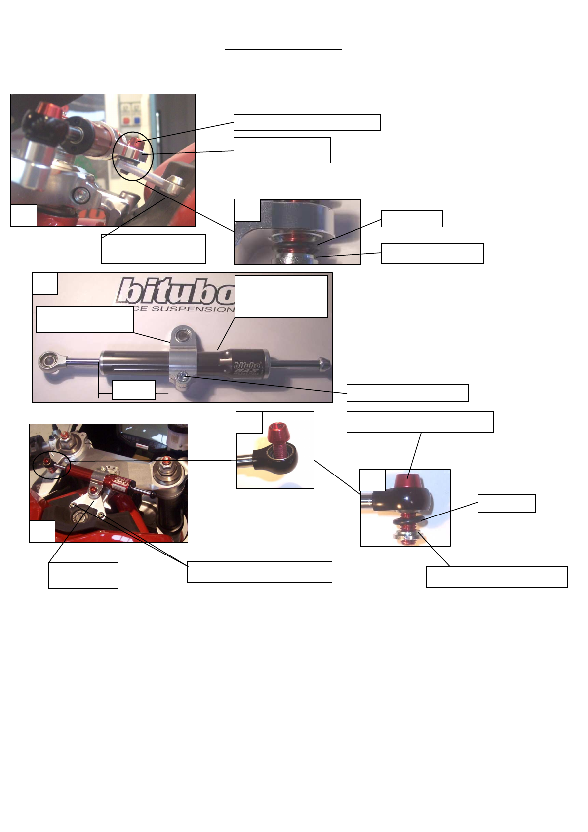
SCHEMA/SCHEME
O-ring 112
Distanziale Ø8 H.10 / Spacer Ø8 H.10
Vite Ergal M8x30 / Ergal screw M8x30
Vite Ergal M8x20 / Ergal screw M8x20
3
Ammortizzatore di
sterzo corsa 60mm
Steering damper stroke
60mm
Attacco ammortizzatore
Steering damper clamp
55mm
Attacco ammortizzatore
Steering damper clamp
O
-
ring 112
Ranella / Spacer
1
2
4
5
6
Vite a brugola / Socket screw
Staffa di sterzo
Steering stirrup
Distanziali riduttori
Reducing spacers
Vite M6 femmina / Femal screw M6
C.D.A. BITUBO s.n.c. – Via A. Volta,24 – 35037 Z.I. Teolo (PD) ITALY – Tel. (+39) 049-990.34.75
Fax (+39) 049-990.34.47 – Cod Fisc. e Part. IVA 02007650282 – E-mail: bitubo@bitubo.com - Internet: http://www.bitubo.com
INDICAZIONI GENERALI – GENERAL INSTRUCTIONS
C.d.a. Bitubo declina ogni responsabilità sul montaggio errato e o sull’uso improprio del materiale contenuto in
questo Kit.
E’ vietato l’utilizzo di questo Kit su strada pubblica.
AVVERTENZE
- Ingrassare le viti con un grasso speciale al rame anti-grippaggio (per esempio Molykote).
- È indispensabile fare installare il KIT da un professionista.
- Leggere attentamente le istruzioni di montaggio prima dell’installazione.
- L’ammortizzatore è garantito per la durata di 2 anni (dalla data del documento fiscale) per
un normale utilizzo (esclusa la competizione)
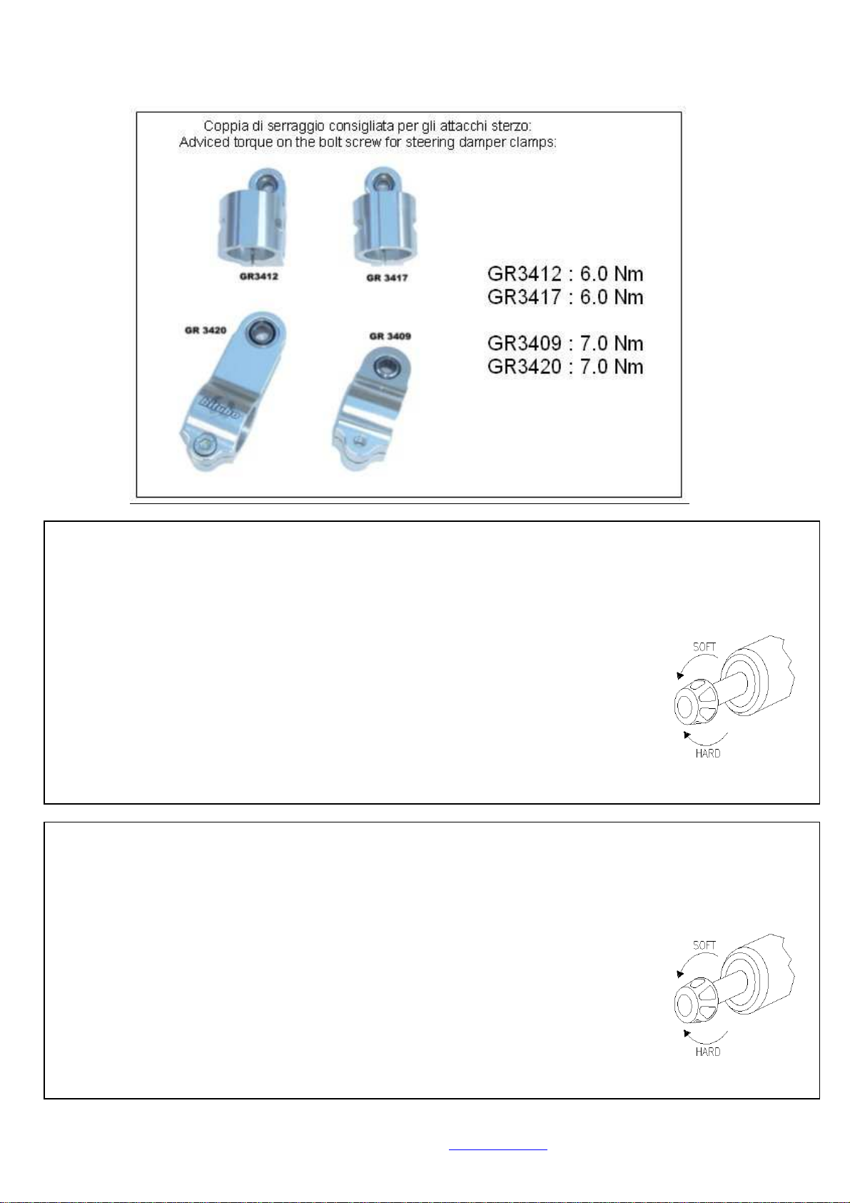
- Dopo aver applicato l’ammortizzatore, consigliamo di utilizzarlo per i primi chilometri alla
frenatura minima (SOFT), in seguito irrigidendolo (HARD) un click per volta.
- Tutte le modifiche del KIT realizzate dall’installatore senza nostri accordi annullano la
garanzia.
C.d.a Bitubo declines all responsibility for incorrect installation or improper use of the material contained in this
Kit.
This Kit must not be used on public roads.
ATTENTION
- Grease the screws with a special copper grease (such as Molykote).
- It is essential that a professional man assembles the kit.
- Read the assembly instructions before starting the assembly.
- The shock absorber is guaranteed for 2 years (date of invoice) for a normal use
(competition excluded).
- After assembling the shock absorber, for the first chilometers use it with soft damping,
then with hard damping, with one release at a time.
- All the modifications of the KIT realised by the installer without our accordance makes void
the Warranty
Table of contents
Other bitubo Motorcycle Accessories manuals


