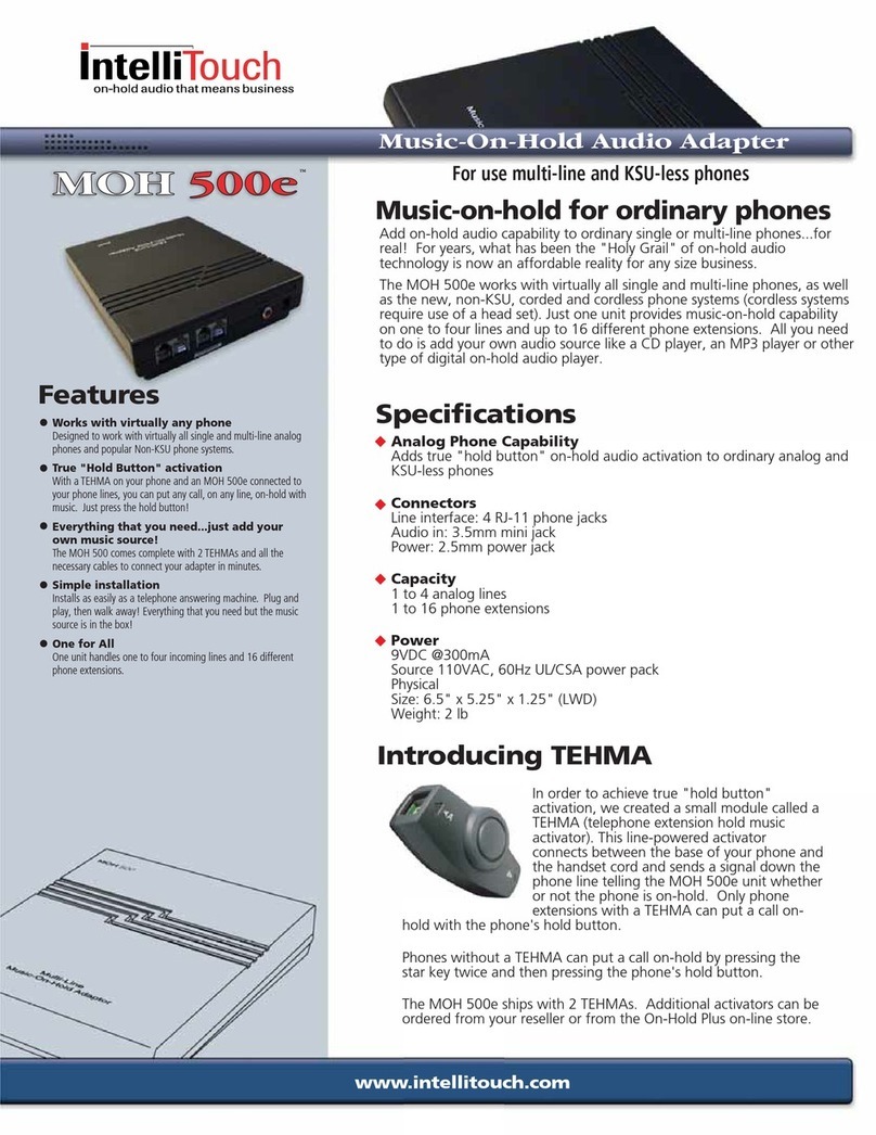
Black Box ASD-4 User manual

CUSTOMER
SUPPORT
INFORMATION
Order toll-free in the U.S. 24 hours, 7 A.M. Monday to midnight Friday: 877-877-BBOX
FREE technical support, 24 hours a day, 7 days a week: Call 724-746-5500 or fax 724-746-0746
Mail order: Black Box Corporation, 1000 Park Drive, Lawrence, PA 15055-1018
FEBRUARY 1994
FX125A-R3
FX125AE-R3
ASD-4
(Automatic Sharing Device)
ON PHONE FAX MODEM
ASD-4

FEDERAL COMMUNICATIONS COMMISSION
AND
INDUSTRY CANADA
RADIO FREQUENCY INTERFERENCE STATEMENTS
This equipment generates, uses, and can radiate radio frequency
energy and if not installed and used properly, that is, in strict
accordance with the manufacturer’s instructions, may cause
interference to radio communication. It has been tested and found
to comply with the limits for a Class B computing device in
accordance with the specifications in Subpart J of Part 15 of FCC
rules, which are designed to provide reasonable protection against
such interference when the equipment is operated in a commercial
environment. Operation of this equipment in a residential area is
likely to cause interference, in which case the user at his own
expense will be required to take whatever measures may be
necessary to correct the interference.
Changes or modifications not expressly approved by the party
responsible for compliance could void the user’s authority to
operate the equipment.
This digital apparatus does not exceed the Class B limits for radio noise
emission from digital apparatus set out in the Radio Interference
Regulation of Industry Canada.
Le présent appareil numérique n’émet pas de bruits radioélectriques
dépassant les limites applicables aux appareils numériques de
classe B prescrites dans le Règlement sur le brouillage radioélectrique
publié par Industrie Canada.
TRADEMARKS USED IN THIS MANUAL
UL is a registered trademark of Underwriters Laboratories
Incorporated.
Any other trademarks mentioned in this manual are acknowledged to be the
property of the trademark owners.

ASD-4
Registration Information
The ASD-4 has been registered with the Federal Communications
Commission (FCC). It meets FCC requirements and may be connected
directly to your telephone line.
Your telephone company may ask for the ASD-4’s FCC registration
number (BZQ8RT-17855-MA-N) and/or its Ringer Equivalence Number, or
REN (0.0 Bells). You can confirm these numbers by comparing them to the
information that appears on the registration label on the bottom of your ASD-
4. You must, upon request, provide this information to your telephone
company.
Use the REN to help determine the maximum number of devices you can
connect to your telephone line without eliminating the devices’ ability to ring
when your number is called. In many areas, the sum of the RENs of all devices
connected to one line should not exceed 5.0 Bells. To determine how many
devices you can connect to your line, contact your local telephone company
to find out the maximum REN for your area.
The FCC requires that connection to the telephone network be made
through Universal Service Order Code (USOC) jacks supplied by the
telephone company. (If you need to order a modular jack for the ASD-4 from
the telephone company, request a USOCRJ11C.) The FCC also requires that
all registered telephone products that are not provided by the telephone
company be repaired only by the manufacturer or a factory-authorized service
agent.
The ASD-4 may not be connected to a party-line or coin-line telephone
network.
If your ASD-4 does not function properly, disconnect it. Follow the
instructions provided in Chapter 6: Troubleshooting concerning repair
service.
If the ASD-4 causes harm to the network, the telephone company may
discontinue your service temporarily. If possible, they will notify you in
advance. But if advance notice is not practical, the telephone company will
notify you as soon as possible. Also, you will be advised of your right to file a
complaint with the FCC if you believe it is necessary.
The telephone company may make changes in the telephone network.
Should these changes affect the ASD-4, the telephone company must notify
you, in writing, to enable you to maintain uninterrupted service.
TABLE OF CONTENTS
Contents
Chapter and Section Page
1. Specifications ............................................................................................. 1
2. Introduction ............................................................................................... 2
2.1 General Information ........................................................................... 2
2.2 The ASD-4’s Ports ............................................................................... 3
3. Installation .................................................................................................. 4
3.1 Installation Overview .......................................................................... 4
3.2 Before You Install ................................................................................ 5
3.2.1 What You’ll Need ...................................................................... 5
3.2.2 What Else We Recommend ...................................................... 5
3.2.3 When You Should Maintain Exclusion .................................... 5
3.3 Installing the ASD-4 on a Single Line with a Single Phone ............. 6
3.4 Connecting Telephone Equipment to the ASD-4 ............................ 7
3.5 Installing the ASD-4 as an Extension [on a Single Line with
Multiple Single-Line Phones] ......................................................... 9
3.5.1 Exclusion Not Maintained ...................................................... 10
3.5.2 Maintaining Exclusion ............................................................ 11
3.6 Installing the ASD-4 on a Two-Line System ..................................... 13
3.6.1 One Single-Line Phone on the ASD-4’s Line ........................ 13
3.6.2 One Two-Line Phone on the ASD-4’s Line ........................... 13
3.6.3 Two or More Phones on the ASD-4’s Line ............................. 16
3.7 Installing the ASD-4 on a KSU/PBX System ................................... 17
3.8 Connecting Caller ID Equipment to the ASD-4 .............................. 19
4. Operation ................................................................................................. 22
4.1 Before You Operate .......................................................................... 22
4.1.1 Services That Won’t Work ...................................................... 22
4.1.2 Understanding Fax CNG Tones ............................................. 22
4.2 Standard Operating Procedures ...................................................... 23
4.2.1 How the ASD-4 Handles Incoming Calls ............................... 23
4.2.2 Answering Incoming Calls ...................................................... 25

ASD-4
Contents (cont’d)
Chapter and Section Page
4.2.3 Retrieving Messages from a Remote Location ...................... 27
4.2.4 Placing an Outbound Call ...................................................... 27
4.2.5 Sending a Fax Transmission ................................................... 28
4.2.6 Sending a Computer (Modem) Transmission ...................... 28
4.2.7 Receiving a Computer (Modem) Call at the
MODEM or FAX Port .......................................................... 29
4.3 Using the Phone Company’s Distinctive Ring Service (DRS)
with the ASD-4 ................................................................................ 32
4.4 Using Remote Message Notification (RMN) ................................... 33
5. Programming the ASD-4 ......................................................................... 37
5.1 The Programming Procedure .......................................................... 37
5.1.1 Accessing the Programming Mode ........................................ 37
5.1.2 Program Entries ...................................................................... 38
5.1.3 Clearing Programming Mistakes ............................................ 39
5.1.4 Exiting the Programming Mode ............................................ 39
5.2 The ASD-4’s Features and Functions ............................................... 40
5.3 The Features (ON/OFF Options) in Detail .................................... 42
5.3.1 Feature [0]: Automatic Ring Reduction ................................ 42
5.3.2 Feature [1]: Open Line Notification (OLN) ........................ 43
5.3.3 Feature [2]: Extension Detection .......................................... 44
5.3.4 Feature [3]: Automatic TAD Transfer ................................... 44
5.3.5 Feature [4]: Pulse Transfer .................................................... 45
5.3.6 Feature [5]: Automatic No Answer Transfer ........................ 45
5.3.7 Feature [6]: CNG Detection ................................................... 46
5.3.8 Feature [7]: Reverse Modem Detection ..................................47
5.3.9 Feature [8]: Remote Message Notification (RMN) .............. 47
5.3.10 Feature [9]: Distinctive Ring Detection .............................. 48
5.3.11 Feature [1][0]: Outbound Voice Exclusion ........................ 48
5.3.12 Feature [1][1]: Reverse Modem Port Selection .................. 49
5.3.13 Feature [1][2]: Automatic Transfer Port Selection ............ 50
5.4 The Functions (Multi-Value Options) in Detail ............................. 51
5.4.1 Function [2][1]: Security Access Code .................................. 51
5.4.2 Function [2][2]: FAX Access Code ....................................... 58

TABLE OF CONTENTS
Contents (cont’d)
Chapter/Appendix and Section Page
5.4.3 Function [2][3]: MODEM Access Code ................................ 52
5.4.4 Function [3][1]: TAD and PHONE Ports’ Distinctive
Ring Assignment .................................................................. 53
5.4.5 Function [3][2]: FAX Port’s Distinctive Ring Assignment ... 54
5.4.6 Function [3][3]: MODEM Port’s Distinctive
Ring Assignment .................................................................. 54
5.4.7 Function [4][0]: Rings to Answer Call .................................. 55
5.4.8 Function [4][1]: Rings Available to the TAD and
PHONE Ports ....................................................................... 56
5.4.9 Function [4][2]: Rings Available to the FAX Port ................ 56
5.4.10 Function [4][3]: Rings Available to the MODEM Port ...... 57
5.4.11 Function [5]: Phantom Ring Style ....................................... 57
5.4.12 Function [6]: Automatic TAD Transfer Timer ................... 58
5.4.13 Function [7]: RMN Phone Number .................................... 59
5.4.14 Function [8]: RMN Conditions ............................................ 60
5.4.15 Function [9][9][9]: Reset to Factory Settings .................... 60
5.5 Sample Programming Sessions ........................................................ 61
5.5.1 Single Change, Programmed Locally .................................... 61
5.5.2 Single Change, Programmed Remotely ................................ 61
5.5.3 Multiple Changes, Programmed Locally ............................... 62
5.5.4 Multiple Changes, Programmed Remotely ........................... 63
6. Troubleshooting ...................................................................................... 64
6.1 Common Concerns ........................................................................... 64
6.2 Calling Black Box .............................................................................. 65
6.3 Shipping and Packaging ................................................................... 66
Appendix A: Quick Start Guide .................................................................... 67
A.1 Installing the ASD-4 .......................................................................... 67
A.2 Operating the ASD-4 ........................................................................ 68
A.2.1 Answering Incoming Calls ..................................................... 68
A.2.2 Using the ASD-4 with a TAD (Answering Machine) ............ 68
A.3 Important Notes ................................................................................ 69

ASD-4
Contents (cont’d)
Appendix and Section Page
A.3.1 Surge Protection ..................................................................... 69
A.3.2 Services That Don’t Work ...................................................... 69
A.4 If You Have Questions ...................................................................... 70
Appendix B: Programming Worksheet ........................................................ 71
Appendix C: Remote Programming Card .................................................... 75

1
CHAPTER 1: Specifications
FCC Registration — BZQ8RT-17855-MA-N
DOC Approval — 1081-56-06A
DOC Load — 20
Ringer
Equivalency — Zero (0.0 Bells)
User Controls — DTMF-tone commands from attached telephone
Indicators — (4) LEDs: ON (power), PHONE, FAX, and MODEM
Connectors — (5) RJ-11 female:
Power — For 120-VAC operation:
From wallmount power supply PS418 (UL®listing
50J5-E87297 or 81J1-E81356, CSA listing
LR57562 or LR84186):
Input: 120 VAC, 60 Hz, 17 watts;
Output: 9 VAC at 1.5 amps;
For 220-VAC operation:
From wallmount power supply PS418E:
Input: 220 VAC, 50 Hz, 17 watts;
Output: 9 VAC at 1.5 amps;
Consumption: 69 watts when line rings, 20 watts at all
other times
Temperature — -40 to 150˚ F (-40 to 65˚ C)
Humidity — Up to 90% noncondensing
Size — 5.75"H x 1.75"W x 6"D (14.6 x 4.4 x 15.2 cm)
Weight — 2 lb. (0.9 kg)
1. Specifications

2
ASD-4
2.1 General Information
Thank you for purchasing an ASD-4. The ASD-4 is a state-of-the-art telephone-
line-sharing device that lets you operate multiple telecommuni-cations
peripherals without installing extra dedicated telephone lines. The ASD-4
quickly directs incoming telephone calls to one of four destinations: a phone,
an answering machine, a fax machine, or a modem or other device.
Here are some of the telephone-activated devices that can be connected to
the ASD-4:
• Modem
• Facsimile (fax) machine
• Fax/modem
• Laser-fax cartridge
• Telephone Answering Device (TAD, answering machine)
• Telephone
• Bulletin Board System (BBS)
• Call diverter
• Credit-card-authorization terminal (CAT)
• Order-process system
• Point-of-sale (POS) terminal
• Money-order-dispensing system
• Fluid-storage system
• Flow monitor
• Energy-management system
• Security alarm and/or monitoring system
• Remote diagnostic system
• Time- and attendance-recording system
2. Introduction

3
CHAPTER 2: Introduction
2.2 The ASD-4’s Ports
There are five modular ports and a power input port on the rear panel of the
ASD-4, as shown in Figure 2-1:
You connect telephone equipment to the modular ports on the ASD-4 as
follows:
Plug the incoming line from the telephone company into the LINE-IN port.
Plug your Telephone Answering Device (TAD, answering machine or
integrated phone/answering machine) into the TAD port. The ASD-4 will
route a call to the TAD and PHONE ports if it answers the call and does not
detect routing tones. (The TAD and PHONE ports are internally connected
and ring simultaneously.)
Connect a single phone line to the PHONE port, regardless of whether
you’re using one phone, multiple phones, or a KSU/PBX system. The ASD-4
will route a call to the TAD and PHONE ports if it answers the call and does
not detect routing tones.
Plug your fax machine into the FAX port. For the ASD-4 to automatically
transfer any fax call with a CalliNG (CNG) tone to your fax machine, the fax
machine must be plugged into this port. You can connect a modem or
fax/modem to this port in lieu of a fax machine.
You can plug any type of telephone device to the MODEM port. If you are
connecting a modem to the ASD-4, we recommend that you plug the modem
into this port.
Figure 2-1. The rear panel of the ASD-4.
LINE-IN TAD PHONE FAX MODEM
12 VAC

4
ASD-4
NOTE
If your application involves only a single phone on the ASD-4’s line, you
might be able to use the basic installation procedure described in the
Quick Start Guide (Appendix A).
3.1 Installation Overview
The ASD-4 can be installed on any type of modular or non-modular system
that consists of one or more lines with one or more phones. A modular system
consists of phone cables that you can plug into and unplug from the
telephone equipment. A non-modular system consists of cables that are “hard-
wired” into the telephone equipment—that is, you can’t plug or unplug the
equipment. The installation process depends on the type of phone system you
have; you might have to get a telephone installer to install the ASD-4 on a
non-modular system.
Many offices have a KSU or a PBX phone system. The ASD-4 works with
either of these systems—or no system at all. Simply follow the appropriate
installation instructions in this chapter.
This chapter explains how to install the ASD-4 in most phone
configurations that appear in a home or office. You can install the ASD-4 into
any one of the following phone configurations:
1. A single line with a single phone.
2. A single line with multiple single-line phones (with the ASD-4 connected
as one extension), maintaining or not maintaining exclusion.
3. Two lines with or without a two-line phone on the same line as the ASD-4,
with or without the ASD-4 connected to the two-line phone, maintaining
or not maintaining exclusion on the ASD-4’s line.
4. A KSU/PBX system.
5. Any of the above with Caller ID equipment.
Installation procedures for each of these configurations are provided in the
following sections.
3. Installation

5
CHAPTER 3: Installation
3.2 Before You Install
3.2.1 W
HAT
Y
OU
’
LL
N
EED
Regardless of your site’s phone configuration, you’ll need the following
equipment to install the ASD-4:
• One 7-ft. (2.1-m) telephone-line cable with male RJ-11 connectors at both
ends—This is provided with your ASD-4.
• Additional telephone-line cables with RJ-11C or RJ-13C connectors—You
will need additional telephone cables for as many pieces of equipment as
you intend to attach to the ASD-4. These cables are usually supplied by
the equipment manufacturer, or you can purchase them through Black
Box.
• Extension cables (optional)—If the equipment you want to attach to the
ASD-4 is not located near the unit, you might need extension cables.
3.2.2 W
HAT
E
LSE
W
E
R
ECOMMEND
We recommend that you use surge protection for all telecommunications
devices. The ASD-4’s power supply should be connected to a surge suppressor
and/or a line conditioner. Also attach in-line surge protectors to the
telephone line conected to the ASD-4. If you need surge-protection
equipment, contact Black Box.
3.2.3 W
HEN
Y
OU
S
HOULD
M
AINTAIN
E
XCLUSION
You must configure the ASD-4 to maintain exclusion if any of the following
conditions apply:
• You would like the ASD-4 to ring any extension phones more than once.
• You want to do anything more sophisticated than place or receive calls
with rotary or pulse-dial extension phones.
• You want to use the ASD-4’s Open Line Notification feature with
extension phones.
For more about maintaining exclusion, see Section 3.5.

6
ASD-4
3.3 Installing the ASD-4 on a Single Line with a Single Phone
Figure 3-1, below, shows a single line/single phone arrangement before
installation of the ASD-4. If you have this type of arrangement, you can install
the ASD-4 yourself using the instructions provided in this section.
Figure 3-2, on the next page, shows the ASD-4 installed for a single-
line/single-phone arrangement. To perform this installation, follow these
steps:
1. Unplug the telephone cable from the wall jack.
2. Plug one end of the telephone cable provided with the ASD-4 into the
LINE-IN port on the back of the ASD-4. Plug the other end of the cable
into the wall jack where the phone was connected.
3. Plug the small end of the AC power cord provided with the ASD-4 into
the power input jack labeled “12VAC” on the back of the ASD-4. Plug the
AC adapter into a standard outlet.
The ASD-4 begins a self-check as soon as you plug it in. The green LED
labeled ON flashes during this test. When the ASD-4 completes its self-check,
the ON LED should stop flashing and remain steadily illuminated. (If the
LED continues to flash, and any peripheral equipment you have already
connected to it is on hook, call for technical support.)
Figure 3-1. Single-line/single-phone arrangement before ASD-4.

7
CHAPTER 3: Installation
3.4 Connecting Telephone Equipment to the ASD-4
Figure 3-3, below, shows telephone equipment connected to the ASD-4. This
figure shows a complete installation for a single line/single phone
arrangement. While connections to wall jacks might be different for other
types of phone configurations, the connections to the ASD-4 remain the same
for all configurations.
Figure 3-3. Equipment connected to the ASD-4 for a
single-line/single-phone arrangement.
Figure 3-2. ASD-4 installed for a single-line/single-phone
arrangement.
Power-Supply
Cord
Power-
Supply
Cord
Telephone
Cable
Phone
Cable
Phone
PC
Modem
Answering Machine
Fax
Machine
ASD-4
Wall
Jack
Wall
Outlet

8
ASD-4
NOTE
Do not place the ASD-4 on, or in close proximity to, peripheral equipment.
NOTE
To make full use of the ASD-4’s automatic switching abilities, you must
connect your equipment to the proper ports, as explained below, and you
must set your equipment to answer on one or two rings.
To connect your telephone equipment to the ASD-4, follow these steps:
1. If you haven’t done so already, connect the phone by plugging its phone
cable into the ASD-4’s PHONE port.
2. To connect a TAD, first plugging a phone cable into the TAD’s phone-
line jack. (This jack will probably be labeled “Line,” “Telephone Line,” or
something similar.) Then plug the other end of the cable into the ASD-4’s
TAD port.
NOTE
The ASD-4 has an Automatic TAD Transfer feature associated with the
TAD port (see Section 5.3.4). The ASD-4 has this feature factory-preset
OFF.
3. To connect a fax machine or a fax/modem card, first plug one end of a
phone cable into the appropriate jack on the fax or fax/modem. (Like
the TAD’s, this jack will probably be labeled “Line,” “Telephone Line,” or
something similar.) Then plug the other end of the cable into the ASD-4’s
FAX port.
4. To connect a telephone device such as a regular modem, plug one end of
a phone cable into the the “incoming phone line” jack on the telephone
device. (Check the device’s manual to make sure you use the right jack
and that you connect the cable properly.) Then plug the other end of this
cable into the ASD-4’s MODEM port.

9
CHAPTER 3: Installation
3.5 Installing the ASD-4 as an Extension [on a Single Line with Multiple
Single-Line Phones]
If you install the ASD-4 as an extension, first determine whether you’ll require
that exclusion be maintained on your system. “Exclusion” means that if one of
the telephone devices on your ASD-4 is using the line (during a phone
conversation, fax transmission, or modem session, for example), and another
device on a different port goes off-hook, it will be excluded from the existing
connection. The ASD-4 will send it a busy tone rather than give it access to the
line.
Exclusion is always present among devices attached to the ASD-4. For
example, if a device on the MODEM port is transmitting or receiving data and
somebody picks up a phone attached to the TAD or PHONE port, the phone
will always get a busy tone and the data exchange will not be disrupted.
NOTE
The TAD and PHONE ports are connected inside the ASD-4, so devices
on these ports never exclude each other.
Exclusion is not automatically “maintained” (extended to extension phones
on the same line) when the ASD-4 is installed as an extension. It is necessary
to work with the phone wiring so that the phone line essentially runs through
the ASD-4 (into its LINE-IN port and out of its PHONE port): This ties all
extension phones on that line into the ASD-4’s PHONE port. This might
seem like a lot of trouble to go to, but when you have a fax or modem
attached to the ASD-4, maintaining exclusion ensures that fax or modem
communications won’t be interrupted if an extension phone is picked up,
and that the fax or modem won’t suddenly drown out a vital conversation.
There are also other effects of exclusion to be mindful of. When exclusion
is not maintained:
• Telephones on the same line as the ASD-4 (except any directly connected
to the ASD-4’s TAD or PHONE ports) ring only one time on an inbound
telephone call.
• The ASD-4 can’t fully support rotary/pulse-dialing extension phones: You
can place and answer calls with them, but you can’t control or program
the ASD-4’s features and functions with them.
• The ASD-4’s Open Line Notification feature (see Section 5.3.2) is not
available to extension phones.

10
ASD-4
If your application requires support for rotary/pulse-dialing extension
phones or Open Line Notification, or if it requires that all extension phones
ring continuously on an inbound call, or if you want to keep extension
phones and your fax or modem from interfering with each other, see Section
3.5.2 for how to install the ASD-4 to maintain exclusion. Otherwise, go on to
Section 3.5.1.
3.5.1 E
XCLUSION
N
OT
M
AINTAINED
If maintaining exclusion isn’t necessary for your application, just choose the
extension line to which you’re going to connect the ASD-4 and use the
procedure explained in Section 3.3. Figure 3-4, below, shows how your system
should appear after you install the ASD-4 as an extension. Refer to Section 3.4
for how to connect your telephone equipment to the ASD-4.
Figure 3-4. The ASD-4 installed as an extension (exclusion not
maintained).
Phone
Cable from
PHONE
Port to
Telephone
Phone
Cable from
LINE-IN
Port to
Wall Jack
Telephone
Wall Jacks
Power-Supply Cable from
12VAC Port to Transformer

11
CHAPTER 3: Installation
3.5.2 M
AINTAINING
E
XCLUSION
To maintain exclusion, the phone line must terminate at the ASD-4, and all
telephone equipment on other extensions must connect to the line through
the ASD-4’s PHONE port as shown in Figure 3-5 on page 14.
CAUTION!
You should be a telephone installer, or be familiar with telephone wiring,
to complete this installation. If you have any questions or are not
confident that you can complete this installation procedure, call
technical support or a professional installer for further instructions.
(Look in your phone book’s Yellow Pages under “Telephone” to locate a
professional installer.)
CAUTION!
Installing the ASD-4 on a given line will briefly interrupt phone service on
that line for all telephone equipment using that line.
For this procedure, you need the following equipment:
• a pair of wire snippers with stripping abilities
• a regular screwdriver and a Phillips screwdriver
• two (2) RJ-11 wallmount-type jacks (available from Black Box)
• two (2) phone cables (also available from Black Box)
• a utility knife
To install the ASD-4 as shown in Figure 3-5, follow these steps:
1. Label one of the RJ-11 jacks “Number 1” and the other “Number 2.”
(Note that the RJ-11 jacks have four posts: the red post is marked [R], the
green post is marked [G], the yellow post is marked [Y], and the black
post is marked [B]. You will be attaching wires to these posts later.)
2. Pick a portion of the telephone line from the phone company to work
on. This portion should be located (A) after the point where the line
enters the premises, (B) before the point that the line routes to any
phone jack, and (C) as close as possible to a place where you can put the
ASD-4.
3. With the utility knife, strip that portion of the cable to expose the red,
green, yellow, and black wires that compose it. (If the color codes of the
wires are not red, green, yellow, and black, call for technical support.)

12
ASD-4
4. Cut the red and green wires and strip their insulation back from the cut
ends to expose not more than an inch (2.5 cm) of their copper cores.
Leave the yellow and black wires intact. At this point, no telephone
equipment at your site should have a dial tone on this line.
NOTE
If possible, mount the RJ-11 jacks in the wall or on some stable, solid
surface before continuing this installation. This might require additional
equipment. Please read the remaining installation instructions before
you mount the jacks, to make sure you understand how the jacks should
be placed.
5. Connect the parts of the cut wires that run to the phone company to jack
“Number 1” by attaching the free end of the red wire to the red post and
the free end of the green wire to the green post.
6. Connect the parts of the cut wires that run to your site’s telephone
equipment to jack “Number 2” by attaching the free end of the red wire
to the red post and the free end of the green wire to the green post.
7. Plug one end of a phone cable into jack “Number 1.” Plug the other end
of this cable into the LINE-IN port on the rear panel of the ASD-4.
8. Plug one end of a second phone cable into the PHONE port on the rear
panel of the ASD-4. Plug the other end of this cable into jack “Number 2.”
9. Connect the other telephone equipment as directed in Section 3.4. If the
ASD-4 is not near the other equipment, you may need to run additional
telephone wiring to the equipment to complete this installation.

13
CHAPTER 3: Installation
3.6 Installing the ASD-4 on a Two-Line System
This arrangement typically occurs in homes with a primary line (residence
number) and a private business line (home-business number). Three sub-
configurations are dealt with in the next three sections:
1. There will be one single-line phone on the same line as the ASD-4.
2. There will be one two-line phone on the same line as the ASD-4.
3. There will be two or more phones on the same line as the ASD-4.
3.6.1 O
NE
S
INGLE
-L
INE
P
HONE ON THE
ASD-4’
S
L
INE
Use the single-line installation procedure described in Section 3.3.
3.6.2 O
NE
T
WO
-L
INE
P
HONE ON THE
ASD-4’
S
L
INE
For this procedure, you will need two three-way adapters, and maybe an extra
phone cable or two. The adapters can be purchased from any telephone or
electronic-equipment dealer. See Figure 3-6 on the next page for a close-up of
a three-way adapter.
Figure 3-5. The ASD-4 installed as an extension (maintaining
exclusion).
Phone
Line’s
Junction
Box
Red
Yellow
Black
Red Green
Green
Phone
Cable from
LINE-IN
Port to
Wall Jack
“Number 1” Phone Cable from
PHONE Port to
Wall Jack “Number 2”
Table of contents
Other Black Box Telephone Accessories manuals

Black Box
Black Box FX6306NA User manual

Black Box
Black Box MC115A User manual

Black Box
Black Box CP103A User manual

Black Box
Black Box Desktop Telephony HS514 User manual

Black Box
Black Box TS210A User manual

Black Box
Black Box MC160A-R2 User manual

Black Box
Black Box HS101A User manual

Black Box
Black Box Phone Coupler II MC155A-R2 User manual

Black Box
Black Box Music On-Hold Plus User manual