Lucent Technologies PARTNER Contact Closure Adjunct User manual

Copyright © 1997 Lucent Technologies Comcode 107915555
All rights reserved Issue 1
Printed in U.S.A. January 1997
PARTNER Contact Closure
Adjunct
Installation Instructions
BEFORE STARTING INSTALLATION, READ AND UNDERSTAND ALL SAFETY INSTRUCTIONS ON
PAGE 2.
The PARTNER® Contact Closure Adjunct is used with a PARTNER Advanced Communications System
processor module (available separately) to activate or deactivate up to two auxiliary devices such as
door locks or door alerts. Your PARTNER Contact Closure Adjunct package should include the parts
shown below. If any parts are missing, call the Lucent Technologies™ hotline at 1 800 628-2888.
CONTACT 2
CONTACT 1
NORMALLY CLOSED –
NORMALLY OPEN –
COMMON –
NORMALLY CLOSED–
NORMALLY OPEN –
COMMON –
PARTNER
Contact Closure Adjunct
PART NO. 107881435 MODEL 950A1
To
Control Unit
50V DC 1 AMP
30V AC 1 AMP
CAUTION:
THIS EQUIPMENT IS FOR INSTALLATION ON LUCENT
TECHNOLOGIES PARTNER COMMUNICATIONS SYSTEMS EQUIPMENT ONLY.
PARTNER Contact Closure Adjunct
#8 x 3/4" (1.9 cm) screws VELCRO
®
strips
14-ft. (4.25 m) phone cord
PARTNER is a registered trademark and Lucent Technologies is a trademark of Lucent Technologies. VELCRO is a
registered trademark of the Velcro companies.

2
Important Safety Instructions
Always follow these basic safety precautions when using this product:
1. Read and understand all instructions.
2. Follow all warnings and instructions marked on the product.
3. DO NOT block or cover the ventilation slots and openings. They prevent the product from overheating. DO NOT
place the product in a separate enclosure, unless proper ventilation is provided.
4. Never spill liquid on the product or drop objects into the ventilation slots and openings. Doing so may result in
serious damage to the components.
5. Repair or service must be performed by a qualified repair person.
6. DO NOT use the product near water or in a wet or damp place (such as a wet basement).
7. Install the product in the same building as the PARTNER Advanced Communications System.
Additional Safety Instructions
for Installation Personnel
1. Install the product to meet all the environmental and electrical requirements listed in the specifications. (See the
PARTNER Advanced Communications System Installation
guide.)
2. DO NOT install telephone wiring during a lightning storm.
3. Never touch uninsulated telephone wires or terminals, unless the telephone line has been disconnected at the
network interface.
4. Use caution when installing or modifying telephone lines.
SAVE THESE INSTRUCTIONS
Important Installation Guidelines
The Contact Closure Adjunct
must
be installed within the same building as the PARTNER ACS processor module.
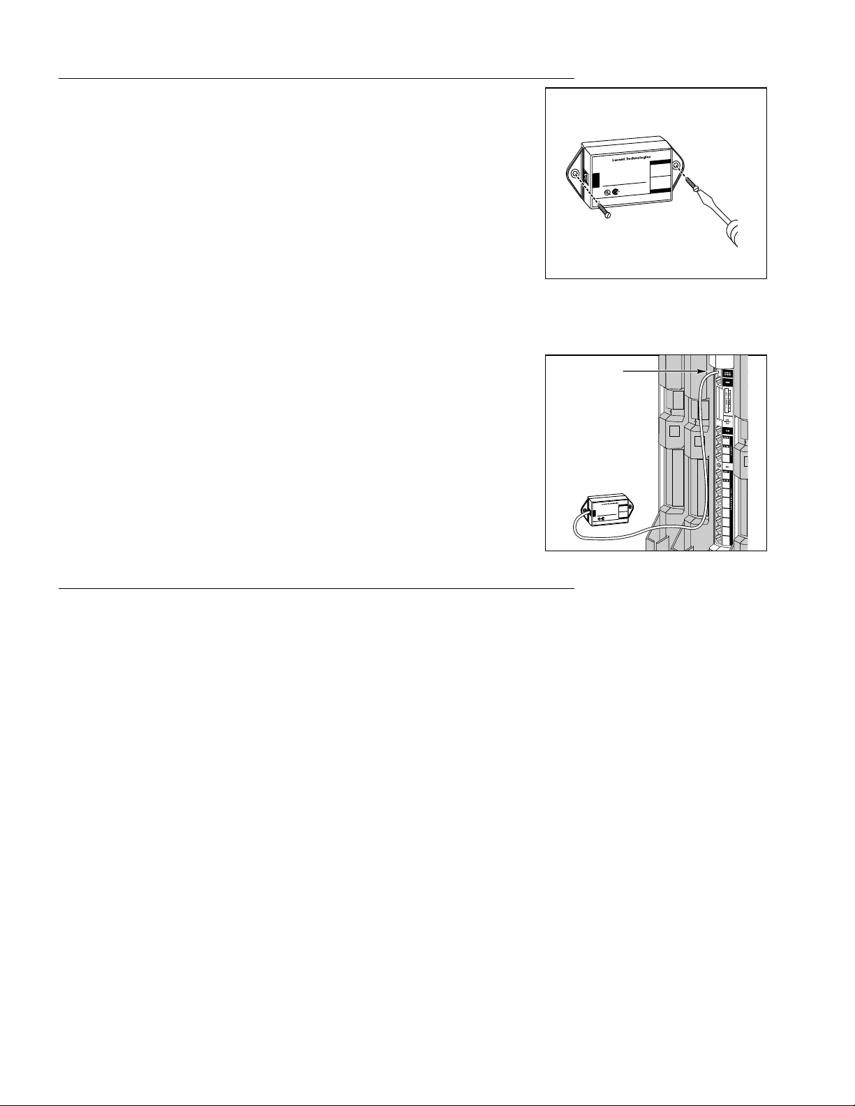
It is recommended that you wall-mount the Contact Closure Adjunct next to the PARTNER ACS processor module;
however, if this is not practical, use the following guidelines, depending upon how many devices you are controlling:
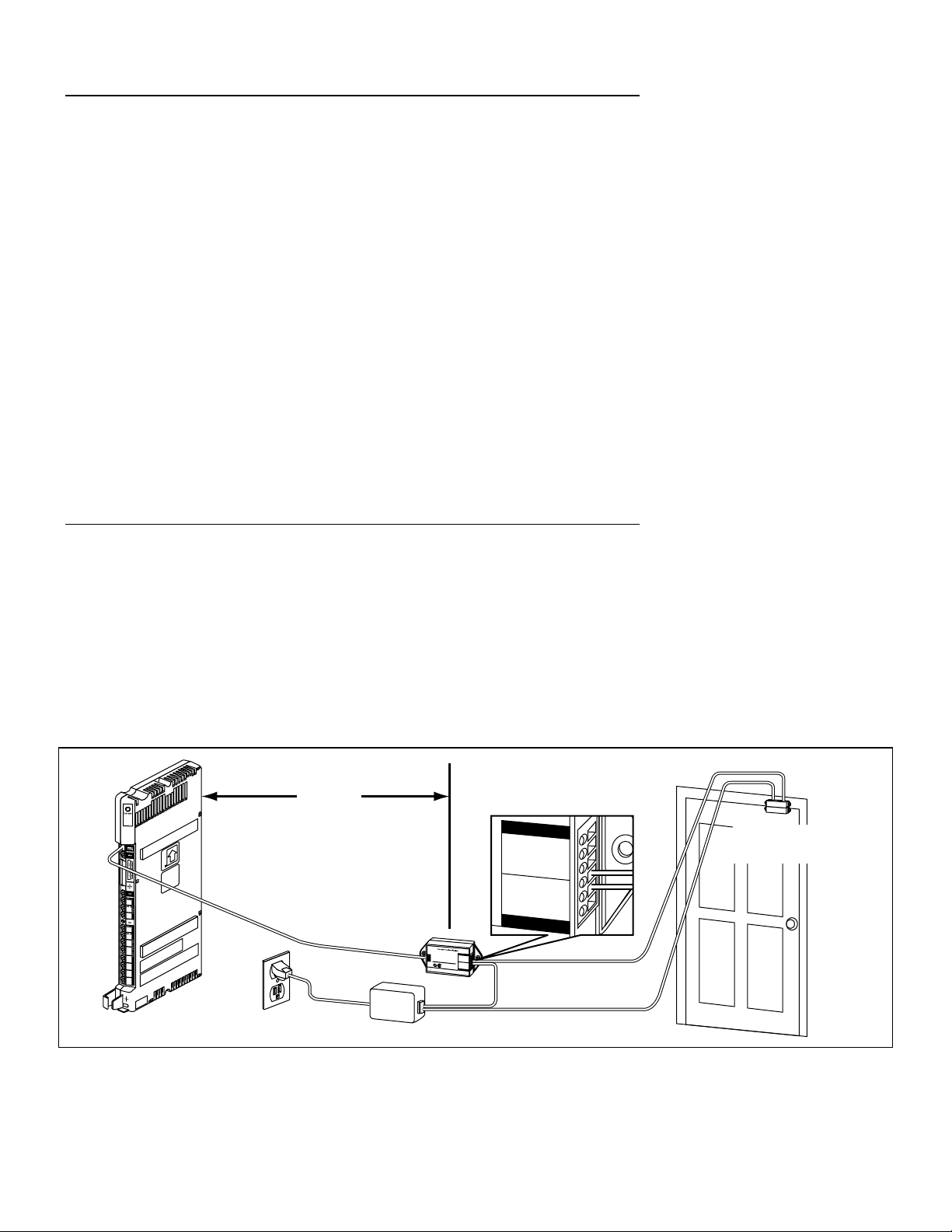
2 devices: Wall-mount the Contact Closure Adjunct within 150 feet (46 m) of the PARTNER ACS processor module.
1 device: Wall-mount the Contact Closure Adjunct within 800 feet (244 m) of the PARTNER ACS processor module.
NOTE:
If you add a second device to the Contact Closure Adjunct and the Adjunct is mounted more than 150 feet (46
m) from the PARTNER ACS processor module, you must reposition the Contact Closure Adjunct to within 150
feet (46 m) of the PARTNER ACS processor module.
The following guidelines apply to any device attached to the Contact Closure Adjunct:
• Maximum rating per closure for the Contact Closure Adjunct is 50VDC, 1 AMP or 30VAC, 1 AMP.
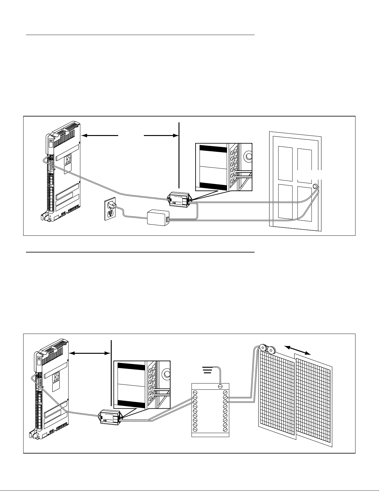
• A surge protector (properly grounded to an approved earth ground) must be installed if the device being
controlled is not located in the same building as the PARTNER ACS processor module and the Contact Closure
Adjunct. The surge protector protects the Contact Closure Adjunct and the PARTNER ACS processor module,
but not the device being controlled. Lucent Technologies 146G Surge Protector—SCL/8 is recommended.
• The maximum distance between the Contact Closure Adjunct and the device being controlled depends upon the
device. Consult the manufacturer of the device to determine this distance.
!
CAUTION:
In the case of a power failure, a security risk can be incurred when the Contact Closure Operation Type is set
to Toggle and an entrance door is wired so that when the feature is activated, the door is locked. If a power
failure occurs, for example, after a user activates the Contact Closure to lock the door for the night, the
Toggle setting flips back to the default (unlocked), and remains off even after power is restored.

3
Wall-Mounting and Connecting the Contact Closure Adjunct
1Mount the PARTNER Contact Closure Adjunct to the wall using
either
the #8 screws or the VELCRO® strips:
•Insert a screw into the wall through the screw hole in the tab at each
end of the Contact Closure Adjunct. Do not overtighten the screws.
•Use the VELCRO strips as follows:
A) Peel the protective paper from one side of the first pair of
VELCRO strips, and firmly press the exposed adhesive to the
back of the Contact Closure Adjunct near the top.
B) Peel the protective paper from one side of the second pair of
VELCRO strip, and firmly press the exposed adhesive to the
back of the Contact Closure Adjunct near the bottom.
CONTACT 2
CONTACT 1
NORMALLYCLOSED –
NORMALLYOPEN –
COMMON –
NORMALLYCLOSED–
NORMALLYOPEN –
COMMON –
PARTNER
Contact Closure Adjunct
PART NO. 107881435 MODEL 950A1
To
Control Unit
50V DC 1 AMP
30V AC 1 AMP
CAUTION:
THIS EQUIPMENT IS FOR INSTALLATIONON LUCENT
TECHNOLOGIES PARTNER COMMUNICATIONSSYSTEMS EQUIPMENT ONLY.
C) Peel the protective paper from the other side of the two
VELCRO strips, exposing the adhesive.
D) Place the Contact Closure Adjunct against the wall. Firmly
press the exposed adhesive to the wall.
2Plug one end of the phone cord into the jack marked “To Control Unit”
on the end of the Contact Closure Adjunct.
3Plug the other end of the phone cord into the CONTACT CLOSURE jack
on the PARTNER ACS processor module, or plug it into a modular wall
jack that is connected to the CONTACT CLOSURE jack.
NOTE:
The Contact Closure Adjunct is polarity-sensitive. Please use the
phone cord provided.
CONTACT2
CONTACT1
NORMALLYCLOSED–
NORMALLYOPEN–
COMMON–
NORMALLYCLOSED–
NORMALLYOPEN–
COMMON–
PARTNER
Contact Closure Adjunct
PARTNO. 107881435 MODEL 950A1
To
ControlUnit
50VDC 1AMP
30VAC 1AMP
CAUTION:
THISEQUIPMENT IS FOR INSTALLATIONON LUCENT
TECHNOLOGIESPARTNER COMMUNICATIONSSYSTEMS EQUIPMENT ONLY.
Contact
Closure Jack
Contact
Closure
Adjunct
Testing the Contact Closure Adjunct Installation
Test that the Contact Closure Adjunct is connected properly using the following procedure. (See
PARTNER
Advanced Communications System Programming and Use
for programming instructions.)
1At extension 10 or 11, press f 0 0 s s to enter programming mode and
do the following:
•Assign extension 10 to Contact Closure Group 1 and Contact Closure Group 2:
A) Dial #612
B) Dial a group number (1 or 2).
C) Dial the extension number (10).
D) Press NP, and repeat Steps B and C for the other Contact Closure Group.
•Set Contact Closures 1 and 2 to Toggle operation:
A) Dial #613
B) Dial a Contact Closure (1 or 2).
C) Press 4for the Toggle operation type.
D) Press nor p, and repeat Step C for the other Contact Closure.
2At extension 10, program a button with lights for Contact Closure 1 and Contact Closure 2:
A) Press c.
B) Dial the extension number (10).
C) Press a programmable button.
D) Press f41 (for Contact Closure 1).
E) Repeat Step C and press f42 (for Contact Closure 2).
3Press f 0 0 to exit programming mode.

4
4At extension 10, press the programmable buttons assigned as
Contact Closure buttons. The green LEDs next to those two buttons
should light.
5Using a multimeter or continuity tester, perform the following tests:
A) Attach the tester probes to the Normally Open and the Common
screws for Contact Closure 1 on the Contact Closure Adjunct. The
tester should indicate continuity between the terminals.
B) Repeat Step 5A for Contact Closure 2.
Intercom
ABC
2DEF
3
1
JKL
5MNO
6
TUV
8WXYZ
9
0
GHI
4
PQRS
7
*
#
Intercom
Ext.
Message
Mic/
HFAI
Feature
+
–
Conf
HoldSpkr
Transfr
6If the tester shows continuity, a licensed electrician can wire the
Contact Closure Adjunct to the auxiliary device or devices you want to
use, in accordance with your local electrical code. [See the
instructions that came with the device(s) and the sample
configurations in “Typical Contact Closure Configurations” below.]
If there is no continuity in either Step 5A or Step 5B, the Contact
Closure Adjunct may be miswired. Continue with Step 7.
NORMALLY CLOSED –
NORMALLY OPEN –
COMMON –
NORMALLY CLOSED–
NORMALLY OPEN –
COMMON –
T
EMS EQUIPMENT ONLY.
CONTACT 2
CONTACT 1
7If the Contact Closure Adjunct is not wired directly to the PARTNER
ACS processor module with the modular cord provided, disconnect
the cord from the Contact Closure Adjunct and from the PARTNER
ACS processor module.
8Plug one end of the 14-foot (4.25 m) D4BU phone cord provided with
your Contact Closure Adjunct into the jack marked “To Control Unit”
on the end of the Contact Closure Adjunct. Plug the other end of the
cord directly into the CONTACT CLOSURE jack on the PARTNER ACS
processor module. [If you have wall-mounted the Contact Closure
Adjunct more than 14 feet (4.25 m) from the processor module, you
will need to remove it from the wall to move it closer. Remove the two
screws or release the VELCRO fastener.]
9Repeat Steps 5A and 5B above.
If the tester shows continuity, the problem is in the wiring for the
CONTACT2
CONTACT1
NORMALLYCLOSED–
NORMALLYOPEN–
COMMON–
NORMALLYCLOSED–
NORMALLYOPEN–
COMMON–
PARTNER
Contact Closure Adjunct
PARTNO. 107881435 MODEL 950A1
To
ControlUnit
50VDC 1AMP
30VAC 1AMP
CAUTION:
THISEQUIPMENT IS FOR INSTALLATIONON LUCENT
TECHNOLOGIESPARTNER COMMUNICATIONSSYSTEMS EQUIPMENT ONLY.
Contact
Closure Jack
Contact
Closure
Adjunct
modular wall jack you want to use. Have a technician check the
wiring. Re-install and retest the Contact Closure Adjunct.
If continuity still does not exist, either the D4BU phone cord or the
Contact Closure Adjunct is defective. Contact the Lucent
Technologies hotline at 1 800 628-2888.
10 Press the programmable buttons assigned as Contact Closure
buttons at extension 10 to deactivate the Contact Closures. The
green LEDs go out.
11 Revise the system programming (Steps 1–3 above) to meet the
requirements of your application.

5
Typical Contact Closure Configurations
Following are examples of typical configurations for a magnetic door lock, an electronic door lock, and an outside
automatic gate. In each of these examples, the Contact Closure Adjunct is wall-mounted within 150 feet (46 m) of
the PARTNER ACS processor module, although the distance could be as great as 800 feet (244 m) since only one
device is being controlled.
System programming of the Contact Closure Group (#612) and the Contact Closure Operation Type (#613) features
is required, and programming a feature button for Contact Closure 1 (F41) [and Contact Closure 2 (F42), if used] is
recommended. When a user presses the button programmed for Contact Closure 1, Contact Closure 1 is activated
and the green LED next to that button lights. If the Contact Closure Operation Type is set to Toggle, Contact Closure
1 remains active until the user presses the button again to deactivate it. The green LED then goes out.
NOTES:
1. If other users are also included in Contact Closure Group 1, Contact Closure 1 could be activated or deactivated
by any one of them. It need not be deactivated by the same user who activated it.
2. If the Contact Closure Operation Type (#613) is set to 1 Second On, 3 Seconds On, or 5 Seconds On, instead of
to Toggle, the Contact Closure deactivates itself when the specified time has elapsed.
3. Be aware that, in the case of a power failure, a security risk can be incurred when the Contact Closure Operation
Type is set to Toggle and an entrance door is wired so that when the feature is activated, the door is locked. If a
power failure occurs, for example, after a user activates the Contact Closure to lock the door for the night, the
Toggle setting flips back to the default (unlocked), and remains off even after power is restored.
Controlling a Magnetic Door Lock
This configuration uses Contact Closure 1 to control a magnetic door lock that is normally locked. The configuration
example has the following characteristics:
• The Normally Closed terminal of Contact Closure 1 is wired (by a licensed electrician) to the magnetic door lock.
• The Common terminal of Contact Closure 1 is wired (by a licensed electrician) to an AC transformer that is
plugged into a 120 VAC wall outlet not controlled by a switch. (The AC transformer is not provided with the
Contact Closure Adjunct.)
• The Contact Closure Operation Type is set to Toggle.
Pressing the programmed button for Contact Closure 1 opens the circuit and releases the door lock. Pressing the
button again relocks it.
NORMALLYCLOSED–
NORMALLYOPEN–
COMMON–
NORMALLYCLOSED–
NORMALLYOPEN–
COMMON–
PARTNER
Contact Closure Adjunct
PARTNO. 107881435 MODEL
To
ControlUnit
50VDC 1AMP
30VAC 1AMP
CAUTION:
THISEQUIPMENT IS FOR
INSTALLATIONON LUCENT
TECHNOLOGIESPARTNER
CONTACT2
CONTACT1
PARTNO. 107881435 MODEL 950A1
PARTNER
3000
AC Transformer
120VAC
Outlet
Contact Closure
Adjunct
C
NORMALLY CLOSED –
NORMALLY OPEN –
COMMON –
NORMALLY CLOSED–
NORMALLY OPEN –
COMMON –
nct
AMP
AMP
CONTACT 2
CONTACT 1
0A1
Magnetic Door
Lock
150 Feet (46 m)
Max.

6
Controlling an Electronic Door Lock
This configuration uses Contact Closure 1 to control an electronic door lock that is normally locked. The
configuration has the following characteristics:
• The Normally Open terminal of Contact Closure 1 is wired (by a licensed electrician) to an AC transformer that is
plugged into a 120 VAC wall outlet not controlled by a switch. (The AC transformer is not provided with the
Contact Closure Adjunct.)
• The Common terminal of Contact Closure 1 is wired (by a licensed electrician) to the electronic door lock.
• The Contact Closure Operation Type is set to 2, which is 3-Seconds On.
Pressing the button programmed for Contact Closure 1 unlocks the door for three seconds.
C
NORMALLY CLOSED –
NORMALLY OPEN –
COMMON –
NORMALLY CLOSED–
NORMALLY OPEN –
COMMON –
nct
AMP
AMP
CONTACT 2
CONTACT 1
0A1
NORMALLYCLOSED–
NORMALLYOPEN–
COMMON–
NORMALLYCLOSED–
NORMALLYOPEN–
COMMON–
PARTNER
Contact Closure Adjunct
PARTNO. 107881435 MODEL
To
ControlUnit
50VDC 1AMP
30VAC 1AMP
CAUTION:
THISEQUIPMENT IS FOR
INSTALLATIONON LUCENT
TECHNOLOGIESPARTNER
CONTACT2
CONTACT1
PARTNO. 107881435 MODEL 950A1
PARTNER
3000
AC Transformer
120VAC
Outlet
Contact Closure
Adjunct
Door Lock
150 Feet (46 m)
Max.
Controlling an Outdoor Automatic Gate
This configuration uses Contact Closure 1 to open and close an exterior electronic gate via a “dry contact.” The
configuration has the following characteristics:
• The Normally Open and the Common terminals of Contact Closure 1 are wired (by a licensed electrician) to a
grounded surge protector. (Lucent Technologies 146G Surge Protector—SCL/8 is recommended.)
• The grounded surge protector is located in the same building as the PARTNER ACS processor module and the
Contact Closure Adjunct, and is wired (by a licensed electrician) to the electronic gate.
• The Contact Closure Operation Type is set to Toggle.
Pressing the button programmed for Contact Closure 1 opens or closes the gate. Pressing the button again stops it.
NORMALLYCLOSED–
NORMALLYOPEN–
COMMON–
NORMALLYCLOSED–
NORMALLYOPEN–
COMMON–
PARTNER
Contact Closure Adjunct
PARTNO. 107881435 MODEL
To
ControlUnit
50VDC 1AMP
30VAC 1AMP
CAUTION:
THISEQUIPMENT IS FOR
INSTALLATIONON LUCENT
TECHNOLOGIESPARTNER
CONTACT2
CONTACT1
PARTNO. 107881435 MODEL 950A1
PARTNER
3000
Contact Closure
Adjunct
Approved
Earth
Ground
Surge Protector
C
NORMALLY CLOSED –
NORMALLY OPEN –
COMMON –
NORMALLY CLOSED–
NORMALLY OPEN –
COMMON –
CONTACT 2
CONTACT 1
150 Feet (46 m)
Max.
Grd
Ground
1
2
3
4
5
6
7
8
Grd
1
2
3
4
5
6
7
8
This manual suits for next models
1
Table of contents
Other Lucent Technologies Telephone Accessories manuals

Lucent Technologies
Lucent Technologies CIB 3020 User manual

Lucent Technologies
Lucent Technologies Definity 8405B User manual

Lucent Technologies
Lucent Technologies INDeX 20DS Turret User manual

Lucent Technologies
Lucent Technologies LULCST Guide

Lucent Technologies
Lucent Technologies SPIRIT 1224 Controller User manual

Lucent Technologies
Lucent Technologies PacketStar PSAX 20 User manual

Lucent Technologies
Lucent Technologies SPIRIT 1224 Controller User manual

Lucent Technologies
Lucent Technologies D-182866 User manual