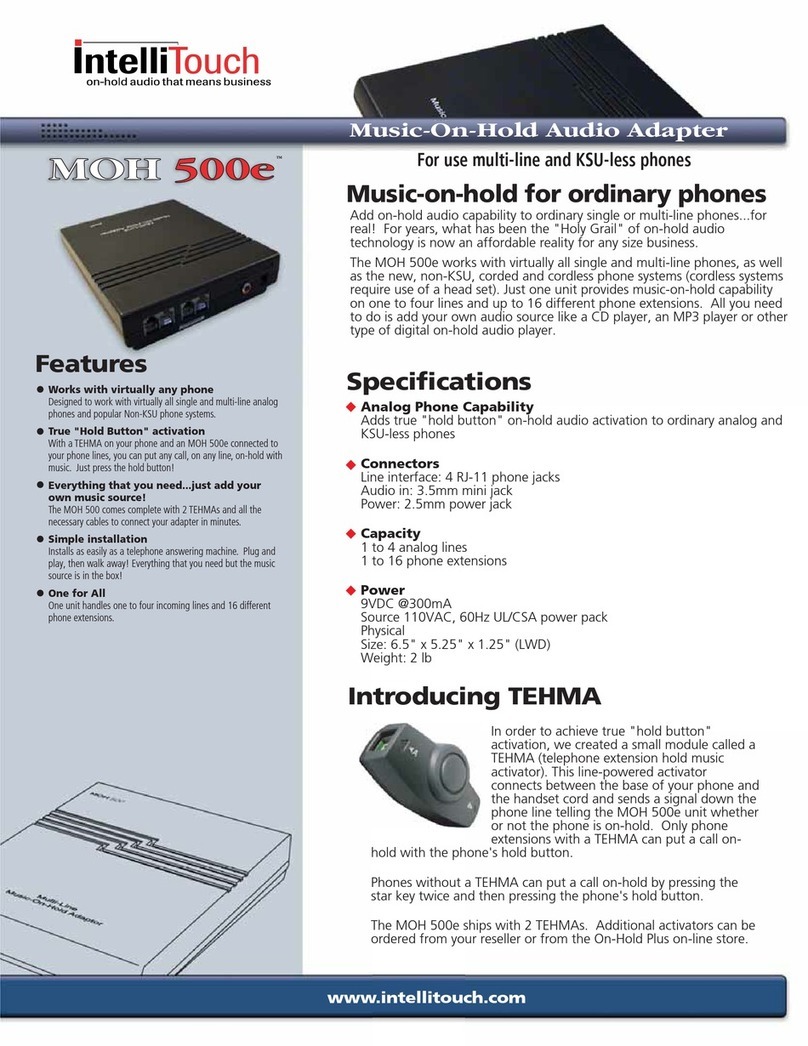
Black Box FX6306NA User manual

CUSTOMER
SUPPORT
INFORMATION
Order toll-free in the U.S. 24 hours, 7 A.M. Monday to midnight Friday: 877-877-BBOX
FREE technical support, 24 hours a day, 7 days a week: Call 724-746-5500 or fax 724-746-0746
Mail order: Black Box Corporation, 1000 Park Drive, Lawrence, PA 15055-1018
SW1
POWER
1 8
LINE
1 2 3 4
PORT
1 2 3 4 5 6 7 8 9 10 11 12
Commercial Phone Line Manager XL 4x12
JULY 1999
FX6306NA
FX6412NA
FX6824NA
FX1236NA
FX1648NA
Plug and Play Commercial Phone Line
Managers: XL-3 x 6; XL 4 x 12;
XL 8 x 24; XL 12 x 36; XL 16 x 48

1
TRADEMARKS
TRADEMARKS USED IN THIS MANUAL
UL is a registered trademark of Underwriters Laboratories Incorporated.
Other product names mentioned in this manual may be trademarks or
registered trademarks of their respective companies and are hereby
acknowledged.

2
PLUG AND PLAY PHONE LINE MANAGER XL
FEDERAL COMMUNICATIONS COMMISSION
AND
INDUSTRY CANADA
RADIO FREQUENCY INTERFERENCE STATEMENTS
This equipment generates, uses, and can radiate radio frequency energy and
if not installed and used properly, that is, in strict accordance with the
manufacturer’s instructions, may cause interference to radio communication.
It has been tested and found to comply with the limits for a Class A
computing device in accordance with the specifications in Subpart J of Part 15
of FCC rules, which are designed to provide reasonable protection against
such interference when the equipment is operated in a commercial
environment. Operation of this equipment in a residential area is likely to
cause interference, in which case the user at his own expense will be required
to take whatever measures may be necessary to correct the interference.
Changes or modifications not expressly approved by the party responsible for
compliance could void the user’s authority to operate the equipment.
This digital apparatus does not exceed the Class A limits for radio noise emission from
digital apparatus set out in the Radio Interference Regulation of Industry Canada.
Le présent appareil numérique n’émet pas de bruits radioélectriques dépassant les limites
applicables aux appareils numériques de classe A prescrites dans le Règlement sur le
brouillage radioélectrique publié par Industrie Canada.

3
FCC REQUIREMENTS
FCC REQUIREMENTS FOR
TELEPHONE-LINE EQUIPMENT
1. The Federal Communications Commission (FCC) has established rules
which permit this device to be directly connected to the telephone
network with standardized jacks. This equipment should not be used on
party lines or coin lines.
2. If this device is malfunctioning, it may also be causing harm to the
telephone network; this device should be disconnected until the source
of the problem can be determined and until the repair has been made.
If this is not done, the telephone company may temporarily disconnect
service.
3. If you have problems with your telephone equipment after installing this
device, disconnect this device from the line to see if it is causing the
problem If it is, contact your supplier or an authorized agent.
4. The telephone company may make changes in its technical operations
and procedures. If any such changes affect the compatibility or use of
this device, the telephone company is required to give adequate notice
of the changes.
5. If the telephone company requests information on what equipment is
connected to their lines, inform them of:
a. The telephone number that this unit is connected to.
b. The ringer equivalence number.
c. The USOC jack required: RJ-11C.
d. The FCC registration number.
Items (b) and (d) can be found on the unit’s FCC label. The ringer
equivalence number (REN) is used to determine how many devices can
be connected to your telephone line. In most areas, the sum of the RENs
of all devices on any one line should not exceed five (5.0). If too many
devices are attached, they may not ring properly.
6. In the event of an equipment malfunction, all repairs should be
performed by your supplier or an authorized agent. It is the
responsibility of users requiring service to report the need for service to
the supplier or to an authorized agent.

4
PLUG AND PLAY PHONE LINE MANAGER XL
CERTIFICATION NOTICE FOR
EQUIPMENT USED IN CANADA
The Canadian Department of Communications label identifies certified
equipment. This certification means that the equipment meets certain
telecommunications-network protective, operation, and safety requirements.
The Department does not guarantee the equipment will operate to the user’s
satisfaction.
Before installing this equipment, users should ensure that it is permissible
to be connected to the facilities of the local telecommunications company.
The equipment must also be installed using an acceptable method of
connection. In some cases, the company’s inside wiring associated with a
single-line individual service may be extended by means of a certified
connector assembly (extension cord). The customer should be aware that
compliance with the above conditions may not prevent degradation of service
in some situations.
Repairs to certified equipment should be made by an authorized Canadian
maintenance facility—in this case, your supplier. Any repairs or alterations
made by the user to this equipment, or equipment malfunctions, may give the
telecommunications company cause to request the user to disconnect the
equipment.
Users should ensure for their own protection that the electrical ground
connections of the power utility, telephone lines, and internal metallic water
pipe system, if present, are connected together. This precaution may be
particularly important in rural areas.
CAUTION:
Users should not attempt to make such connections themselves, but
should contact the appropriate electric inspection authority, or
electrician, as appropriate.
The LOAD NUMBER (LN) assigned to each terminal device denotes the
percentage of the total load to be connected to a telephone loop which is
used by the device, to prevent overloading. The termination on a loop may
consist of any combination of devices, subject only to the requirement that
the total of the load numbers of all the devices does not exceed 100.

5
NOM STATEMENT
NORMAS OFICIALES MEXICANAS (NOM)
ELECTRICAL SAFETY STATEMENT
INSTRUCCIONES DE SEGURIDAD
1. Todas las instrucciones de seguridad y operación deberán ser leídas antes
de que el aparato eléctrico sea operado.
2. Las instrucciones de seguridad y operación deberán ser guardadas para
referencia futura.
3. Todas las advertencias en el aparato eléctrico y en sus instrucciones de
operación deben ser respetadas.
4. Todas las instrucciones de operación y uso deben ser seguidas.
5. El aparato eléctrico no deberá ser usado cerca del agua—por ejemplo,
cerca de la tina de baño, lavabo, sótano mojado o cerca de una alberca,
etc..
6. El aparato eléctrico debe ser usado únicamente con carritos o pedestales
que sean recomendados por el fabricante.
7. El aparato eléctrico debe ser montado a la pared o al techo sólo como
sea recomendado por el fabricante.
8. Servicio—El usuario no debe intentar dar servicio al equipo eléctrico más
allá a lo descrito en las instrucciones de operación. Todo otro servicio
deberá ser referido a personal de servicio calificado.
9. El aparato eléctrico debe ser situado de tal manera que su posición no
interfiera su uso. La colocación del aparato eléctrico sobre una cama,
sofá, alfombra o superficie similar puede bloquea la ventilación, no se
debe colocar en libreros o gabinetes que impidan el flujo de aire por los
orificios de ventilación.
10. El equipo eléctrico deber ser situado fuera del alcance de fuentes de
calor como radiadores, registros de calor, estufas u otros aparatos
(incluyendo amplificadores) que producen calor.

6
PLUG AND PLAY PHONE LINE MANAGER XL
11. El aparato eléctrico deberá ser connectado a una fuente de poder sólo
del tipo descrito en el instructivo de operación, o como se indique en el
aparato.
12. Precaución debe ser tomada de tal manera que la tierra fisica y la
polarización del equipo no sea eliminada.
13. Los cables de la fuente de poder deben ser guiados de tal manera que no
sean pisados ni pellizcados por objetos colocados sobre o contra ellos,
poniendo particular atención a los contactos y receptáculos donde salen
del aparato.
14. El equipo eléctrico debe ser limpiado únicamente de acuerdo a las
recomendaciones del fabricante.
15. En caso de existir, una antena externa deberá ser localizada lejos de las
lineas de energia.
16. El cable de corriente deberá ser desconectado del cuando el equipo no
sea usado por un largo periodo de tiempo.
17. Cuidado debe ser tomado de tal manera que objectos liquidos no sean
derramados sobre la cubierta u orificios de ventilación.
18. Servicio por personal calificado deberá ser provisto cuando:
A: El cable de poder o el contacto ha sido dañado; u
B: Objectos han caído o líquido ha sido derramado dentro del
aparato; o
C: El aparato ha sido expuesto a la lluvia; o
D: El aparato parece no operar normalmente o muestra un cambio en su
desempeño; o
E: El aparato ha sido tirado o su cubierta ha sido dañada.

7
CONTENTS
Chapter Page
1. Specifications..................................................................................................8
2. Introduction ................................................................................................10
2.1 Description ........................................................................................10
2.2 What’s Included ................................................................................11
3. Installation....................................................................................................12
3.1 Connecting the Telephone Lines and IST Devices ........................13
3.2 Connecting the Data Port..................................................................16
3.3 Setting the Switches ..........................................................................16
3.4 Connecting the AC Adapter..............................................................19
4. Operation ....................................................................................................20
4.1 Incoming Calls ..................................................................................20
4.2 Outgoing Calls....................................................................................21
4.3 Data-Transmission Speed ..................................................................21
4.4 Power-Failure Transfer ......................................................................22
4.5 Non-Volatile Memory ........................................................................22
5. Troubleshooting ..........................................................................................23
5.1 Common Problems ............................................................................23
5.2 Calling Black Box ..............................................................................24
5.3 Shipping and Packaging ....................................................................24
Appendix: Connection Log ............................................................................25
Contents

8
PLUG AND PLAY PHONE LINE MANAGER XL
User Connections — All models: Mini jack for power supply;
FX6306NA: (3) RJ-11 modular jacks for
telephone lines, (6) RJ-11 modular jacks for
industry-standard telephone devices; FX6412NA:
(4) RJ-11 modular jacks for telephone lines, (12)
RJ-11 modular jacks for industry-standard
telephone devices; FX6824NA: (8) RJ-11
modular jacks for telephone lines, (24) RJ-11
modular jacks for industry-standard telephone
devices; FX1236NA: (12) RJ-11 modular jacks for
telephone lines, (36) RJ-11 modular jacks for
industry-standard telephone devices; FX1648NA:
(16) RJ-11 modular jacks for telephone lines,
(48) RJ-11 modular jacks for industry-standard
telephone devices
Indicators — FX6306NA: (3) telephone line-in-use LEDs,
(6) IST device-in-use LEDs, (1) Power-on LED;
FX6412NA: (4) telephone line-in-use LEDs, (12)
IST device-in-use LEDs, (1) Power-on LED;
FX6824NA: (8) telephone line-in-use LEDs, (24)
industry-standard telephone device-in-use LEDs,
(1) Power-on LED;
FX1236NA: (12) telephone line-in-use LEDs,
(36) IST device-in-use LEDs, (2) Power-on LEDs;
FX1648NA: (16) telephone line-in-use LEDs,
(48) IST device-in-use LEDs, (2) Power-on LEDs
Compliance — FCC Part 68 registered; FCC Part 15 registered;
Ringer Equivalence 0.7B; UL listed 81J1, E81356,
CSA-power supply
Power — Wallmount AC adapter; 9V, 1 A, 115 VAC, 60 Hz;
UL®and CSA
NOTE
FX1236NA and FX1648NA use two power supplies.
1. Specifications
9
Size — FX6306NA: 2.45"H x 6.2"W x 10.2"D
(6.2 x 15.7 x 25.9 cm); FX6412NA: 2.45"H x
11.45"W x 10.2"D (6.2 x 29.1 x 25.9 cm);
FX6824NA: 4.25"H x 11.45"W x 10.2"D (10.8 x
29.1 x 25.9 cm); FX1236NA: 5.25"H x 19"W x
10.2"D (13.4 x 48.3 x 25.9 cm); FX1648NA: 7"H
x 19"W x 10.2"D (17.8 x 48.3 x 25.9 cm)
Weight — FX6306NA: 2 lb. (0.9 kg);
FX6412NA: 5 lb. (2.3 kg);
FX6824NA: 8 lb. (3.6 kg);
FX1236NA: 11 lb. (4.9 kg);
FX1648NA: 14 lb. (6.4 kg)
CHAPTER 1: Specifications

10
PLUG AND PLAY PHONE LINE MANAGER XL
2.1 Description
The Plug and Play Phone Line Manager XL allows a company to use the
minimum number of telephone lines required to support the maximum
number of industry-standard telephone (IST) devices. An IST is any type of
telecommunications device that works on a standard telephone company
telephone line, such as modems, fax machines, fax/modems, credit-card
terminals, etc. The Plug and Play Phone Line Manager XL can save a
company hundreds to thousands of dollars per year in telephone-line
installation costs and recurring monthly line charges.
The Plug and Play Phone Line Manager XL can work with any type of
standard telephone line: POTS (Plain Old Telephone Service) or Centrex,
touchtone or rotary. It also works with any industry-standard telephone lines
with any type of telephone system—you can even share industry-standard
telephone extensions on any telephone system.
The Plug and Play Phone Line Manager XL is designed for analog telephone-
line switching in the U.S. and Canada only. The switching is accomplished
using metallic contacts to ensure no degradation of the signal, for any suitable
application. You can be sure that any device which works directly with an
analog phone line will work equally well through a Plug and Play Phone Line
Manager XL.
The Plug and Play Phone Line Manager XL 3 x 6 can support up to six IST
devices and three telephone lines. The Plug and Play Phone Line Manager
XL 4 x 12 can support up to twelve IST devices and four telephone lines. The
Plug and Play Phone Line Manager XL 8 x 24 can support up to twenty-four
IST devices and eight telephone lines. The Plug and Play Phone Line
Manager XL 12 x 36 can support up to 36 IST devices and 12 telephone lines.
The Plug and Play Phone Line Manager XL 16 x 48 can support up to 48 IST
devices and 16 telephone lines. You can also link or daisychain multiple Plug
and Play Phone Line Manager XL units together to support an even greater
number of IST devices and telephone lines. Please see Section 3.1.1,
Networking Multiple Units Together, for other possible line and device
combinations.
The Plug and Play Phone Line Manager XL has inbound and outbound
calling capabilities. On inbound calls, ringing lines connect directly through
to specific IST ports. This ring-through capability allows the Plug and Play
2. Introduction

11
Phone Line Manager XL to reside unobtrusively in front of many telephone
systems: KSU or PBX, analog or digital. In this situation, the Plug and Play
Phone Line Manager XL can share outgoing IST devices with a main pool of
voice telephone lines.
The Plug and Play Phone Line Manager XL is an electronic switch and has
been designed for durability and ease of maintenance, but some care should
be taken when handling it. Do not expose the Plug and Play Phone Line
Manager XL to high humidity or extreme electrical fields. As with all
electronic devices, you should take precautions against static electricity.
2.2 What’s Included
Unpack the Plug and Play Phone Line Manager XL. Check to make sure the
Plug and Play Phone Line Manager XL was not damaged in shipping. If you
notice any obvious damage that occurred in transit, notify your shipper
immediately.
Verify that you have everything that should be included with your Plug and
Play Phone Line Manager XL. A checklist is provided below.
•Plug and Play Phone Line Manager XL 3 x 6, 4 x 12, 8 x 24, 12 x 36
(includes one 4 x 12 and one 8 x 24), or 16 x 48 (includes two 8 x 24 units)
•Wallmount AC Adapter
•Rubber feet and hook & loop fastener with mounting instructions
•This manual
The 12 x 36 and 16 x 48 models will also include:
•One 11.45" x 10.2" black finished steel 0.090" shelf
•One 19"W black finished steel 0.125" shelf faceplate
•Four truss-head screws, 10-32, 3⁄8" long
•Six truss-head screws, 10-32, 1⁄2" long
•Four nylon insert nuts, 10-32
•Shelf assembly instructions
If anything is missing from your order, call us at 724-746-5500.
CHAPTER 2: Introduction

12
PLUG AND PLAY PHONE LINE MANAGER XL
Select an appropriate location away from direct sources of heat or cold. The
Plug and Play Phone Line Manager XL can be stacked on a desk or table, or
mounted vertically on a wall. Typically the Plug and Play Phone Line Manager
XL is located in the same area as other computer network or telephone
equipment. All device and power connections are made in the rear of the
unit. All connections or disconnections must be made with power removed from the
unit.
The FX1236NA and FX1648NA mount in a 19" rack. First, locate the four pre-
drilled holes in the bottom of the faceplate and front of the shelf. Align the
faceplate holes with the shelf holes and then insert the screws through the
holes. Place the nylon insert nuts onto the back of the screws. Tighten the
screws until hand-tight. Now you can mount the shelf in a standard 19" rack
using the supplied 10-32, 1⁄2" long truss-head screws. Once the shelf is
mounted, the units can be placed on the shelf with front-panel LEDs facing
forward or with the RJ-11 connectors facing forward for patch-panel
applications.
We have included both self-adhesive feet and an adhesive-backed hook & loop
fastener. The feet are useful when the unit will be resting on a flat surface.
The hook & loop fastener is useful when mounting the unit to a wall or other
vertical surface. The hook & loop fasteners also provide rackmount stability
when installed between the two Phone Line Manager units on the 12 x 36 and
16 x 48 models. To use the hook & loop fastener, keep the hook and loop
halves together while peeling the plastic backing from one side and stick it to
one of the bottom corners of the unit. Repeat the process for all four corners.
Now peel the remaining plastic backing from the hook and loop halves.
Carefully line the Plug and Play Phone Line Manager XL up where you want
to mount it and press the unit firmly to the mounting surface. Once installed
using the hook & loop fastener, the unit may be removed from the mounting
surface by grasping the unit and pulling firmly away from the mounting
surface. To remount, align the hook & loop halves together and press firmly
together.
3. Installation

13
CHAPTER 3: Installation
3.1 Connecting the Telephone Lines and IST Devices
NOTE
In the following description and throughout this manual, the first number
listed refers to the LINE and IST Ports available on the Plug and Play
Phone Line Manager XL 3 x 6. The second and third numbers (listed in
parentheses) refers to the LINE and IST Ports available on the Plug and
Play Phone Line Manager XL 4 x 12 and the Plug and Play Phone Line
Manager XL 8 x 24. The 12 x 36 is actually a 4 x 12 and a 8 x 24 Phone
Line Manager. The 16 x 48 is actually two 8 x 24 units. You can use the 12
x 36 and 16 x 48 as two separate Phone Line Manager units, or network
them together as explained in Section 3.1.1.
Connect your telephone lines to the LINE Ports numbered 1 through 3 (4 or
8), starting with LINE Port 1. If connecting fewer than 3 (4 or 8) lines, leave
the higher numbered LINE Ports unconnected. Similarly, connect the RJ-11
modular line cords from your IST devices to the desired IST Ports, starting
with IST Port 1. If connecting fewer than 6 (12 or 24) IST devices, leave the
higher-numbered IST Ports unconnected. See the information on the next
page for additional information concerning the connection of the Line Ports
and Incoming IST Ports.
When connecting telephone lines and IST devices to the Plug and Play Phone
Line Manager XL, the devices that will receive incoming calls must be
connected to the Incoming IST Ports as listed in the chart below. The highest-
priority incoming-call device should be connected to IST Port 1, and its
associated telephone line should be connected to LINE Port 1. The next-
highest-priority incoming-call device should be connected to IST Port 2 and
its associated telephone line should be connected to LINE Port 2, etc.
Incoming calls to the first line ports of the Plug and Play Phone Line Manager
XL are passed directly through to the first IST Ports; therefore, the number of
IST devices that can accept incoming calls is equal to the number of
telephone lines connected to the Phone Line Manager XL.
Incoming IST Ports
3 x 6 Model 4 x 12 Model 8 x 16 Model
LINE Port IST Port LINE Port IST Port LINE Port IST Port
111111
222222
333333
4444
513
614
715
816

14
PLUG AND PLAY PHONE LINE MANAGER XL
After connecting the incoming IST devices and associated lines to the Plug
and Play Phone Line Manager XL, proceed in connecting any additional
outgoing devices and telephone lines to the respective Plug and Play Phone
Line Manager XL IST Ports and LINE Ports.
3.1.1 N
ETWORKING
M
ULTIPLE
P
HONE
L
INE
M
ANAGER
U
NITS
T
OGETHER
You can network the Phone Line Managers together to provide additional IST
device ports, telephone line ports, or both. The method you choose to
network the units together depends on the quantity of IST devices, the
telephone line use, and the application.
NOTE
The following diagrams use 4 x 12 Phone Line Manager units. The same
connections apply to 4 x 12 or 8 x 24 units. If you have questions about
your network application, please call Black Box Technical Support.
Example 1: Providing Additional IST Device Ports
When an application requires more IST ports than one Phone Line Manager
can provide, you can network two or more Phone Line Managers together.
Simply connect IST ports on the first Phone Line Manager to the line ports
on the second Phone Line Manager. Providing more than one network
connection between the two Phone Line Managers will permit more than one
IST device on the second Phone Line Manager to simultaneously access the
telephone lines on the first Phone Line Manager. A 3 to 1 ratio of devices to
lines is typical, although your particular application may be different. The
goal is to be able to provide dial tone and outbound call capability to all
outbound IST devices, while maintaining inbound call availability for those
applications and IST devices that require it. Networking two 4 x 12 Phone
Line Manager units together in this manner will create a 4 x 20 Phone Line
Manager. Networking two 8 x 24 Phone Line Managers together creates an 8
x 40 Phone Line Manager, while networking three 8 x 24s will create an 8 x 56
Phone Line Manager.

15
Figure 3-1. 4 x 20 Network Application.
In the above example, IST devices on the first and the second Phone Line
Manager will have equal outbound access to the four telephone lines since
four network links have been provided. For inbound calls on the
incoming/outgoing Phone Line Manager, the four telephone lines will ring
the first four IST ports on the first Phone Line Manager. All other IST ports
(5-12) on the first Phone Line Manager and all IST ports (1-12) on the
second Phone Line Manager are for outbound calling only.
Example 2: Providing Additional Line Ports and Device Ports
If the quantity of telephone lines and IST devices that are required for your
application exceed the capacity of one Phone Line Manager, then you can
network two or more units together. In this application, to increase the Phone
Line Manager capacity to handle the quantity of lines and device ports you
need, connect one half of the telephone lines to the first Phone Line
Manager and the other half of the telephone lines to the the second Phone
Line Manager. Leave at least one Line port and one IST port open on each
Phone Line Manager for networking. By connecting Line Port #1 on the first
Phone Line Manager to the last IST port on the second Phone Line Manager,
and by connecting Line Port #1 on the second Phone Line Manager to the
last IST port on the first Phone Line Manager, an outgoing call from any IST
port can access the telephone lines on any networked Phone Line Manager.
Networking two Phone Line Managers together in this manner will allow an
IST device to search and gain access to an available telephone line connected
4 x 12 LineShare (1st) 4 x 12 LineShare (2nd)
4 Telephone
Lines
8 IST
Devices
12 IST
Devices
Network
Links
4 x 12 Phone Line Manager (1st) 4 x 12 Phone Line Manager (2nd)

16
PLUG AND PLAY PHONE LINE MANAGER XL
to either Phone Line Manager unit. Networking two 4 x 12 units together by
this method will effectively create a 6 line x 22 IST port Phone Line Manager.
Networking two 8 x 24 Phone Line Managers together will create a 14 x 46
Phone Line Manager, and networking three 8 x 24 Phone Line Managers
together will create a 21 x 69 Phone Line Manager.
Figure 3-2. 6 x 22 Networked Application.
In the above example, IST devices on the first and the second Phone Line
Manager will have equal outbound access to the three telephone lines on
their own Phone Line Manager. The fourth outbound call will be networked
to the other Phone Line Manager and have access to those three telephone
lines over the network link that is provided. For inbound calls, the three
telephone lines on each Phone Line Manager will ring the direct connect IST
ports (2-4) on the same Phone Line Manager. All other IST ports (except
network links) are for outbound calling only.
3.2 Connecting the Data Port
The RJ-11 jacks on the back panel labeled DATA are for field service and
diagnostic use only, and should be left unconnected in the Plug and Play
Phone Line Manager XL setup.
4 x 12 LineShare (1st) 4 x 12 LineShare (2nd)
Link
3 Telephone
Lines
3 Telephone
Lines
11 IST
Devices 11 IST
Devices
Link
4 x 12 Phone Line Manager (1st) 4 x 12 Phone Line Manager (2nd)

17
CHAPTER 3: Installation
3.3 Setting the Switches
SW1 (and SW2 on the 8 x 24 model) on the front panel of the Plug and Play
Phone Line Manager XL must be set to identify the line connections and
operation as follows. Switches SW1-1 and SW1-5 correspond to Line 1,
switches SW1-2 and SW1-6 correspond to Line 2, etc. SW2 is configured
identically to SW1 on the Plug and Play Phone Line Manager XL 8 x 24, and
controls Lines 5 through 8.
Table 3-1. SW1 Configuration
Ln 1 Ln 2 Ln 3 Ln 4* Ln 1 Ln 2 Ln 3 Ln 4*
SW1-1 SW1-2 SW1-3 SW1-4 SW1-5 SW1-6 SW1-7 SW1-8
Line Present ON ON ON ON
Ln Not Pres OFF OFF OFF OFF
Hunt Enabled ON ON ON ON
Hunt Disabled OFF OFF OFF OFF
*For the Plug and Play Phone Line Manager XL 3 x 6, SW1-4 and SW1-8 are
not present.
Table 3-2. SW2 Configuration
Ln 5 Ln 6 Ln 7 Ln 8 Ln 5 Ln 6 Ln 7 Ln 8
SW2-1 SW2-2 SW2-3 SW2-4 SW2-5 SW2-6 SW2-7 SW2-8
Line Present ON ON ON ON
Ln Not Pres OFF OFF OFF OFF
Hunt Enabled ON ON ON ON
Hunt Disabled OFF OFF OFF OFF
The Line Present/Not Present settings determine which of the lines are
checked for purposes of outgoing line access. When a device connected to an
IST Port goes off-hook, the Plug and Play Phone Line Manager XL will search
for an available line. The Plug and Play Phone Line Manager XL always
searches the higher-numbered LINE Ports first. Example: If four lines are
connected to the Plug and Play Phone Line Manager XL, the Plug and Play
Phone Line Manager XL will check LINE Port 4 first, then LINE Port 3, then
LINE Port 2, etc. The only exception to this is the first IST Ports (those IST
Ports that have a corresponding line connected to them). Each of these IST
Ports checks its own” line first. Example: IST Port 2 checks for line availability

18
PLUG AND PLAY PHONE LINE MANAGER XL
(dial tone) on LINE Port 2 first. If LINE Port 2 is not available (another
device is using it), the Plug and Play Phone Line Manager XL will check LINE
Port 4, then LINE Port 3, etc. If all lines are in use, then the requesting IST
Port will get no dial tone to indicate no line available.
Each “line present” switch is factory-set initially in the “ON” position. If a
LINE Port has no line connected to it, or if the line is to be restricted for
incoming calls only, the “line present” switch should be set to the “OFF”
position. The Hunt Enabled/Disabled settings determine the mode of
operation for handling an incoming call. When hunt is disabled (the Hunt
Enabled/Disabled switch is in the “OFF” position), an incoming call is
connected through to the same-numbered IST Port. Example: LINE Port 1
connects to IST Port 1, LINE Port 2 to IST Port 2, etc. If the desired IST Port
is in use (connected to another line), the call is left unconnected in the Plug
and Play Phone Line Manager XL, causing a ring-no-answer (RNA) condition.
This is desirable on a modem or fax line, since normally an incoming line is
associated with a single device that must be available when called. However,
when the Plug and Play Phone Line Manager XL is installed in front of a
telephone system KSU or PBX, this RNA condition defeats the hunt sequence
that a telephone company normally provides when an incoming call is
directed to a main number which is busy. In such an application you would
set hunt enabled “ON” for each line connected to the Plug and Play Phone
Line Manager XL in front of the KSU or PBX. This causes the Plug and Play
Phone Line Manager XL to hunt from IST Port to IST Port on an incoming
call when the first port or ports in the sequence are busy.
In most applications, the Hunt Enabled/Disabled switches should be in the
“OFF” position. The switches should be set to the “ON” position only when an
application calls for an incoming call ringing into a device that is busy to
forward to the next device. The following are incoming-call applications
where hunt enabled should be set to the “ON” position: modem pooling, fax
pooling, and sharing lines with a KSU or PBX telephone system. You must set
at least two or more consecutive switches to the “ON” position to create a loop
or pool.
Since the Plug and Play Phone Line Manager XL routes the 3 (4 or 8)
telephone lines directly through to the Incoming IST Ports, as listed in
Section 3.1, take this into account when placing the Plug and Play Phone Line
Manager XL in front of a KSU or PBX system, or when matching incoming
telephone numbers with IST devices during installation. Only the Incoming
IST device ports are capable of receiving incoming calls.
Each “hunt enabled” switch is factory-set initially in the “OFF” position.

19
CHAPTER 3: Installation
3.4 Connecting the AC Adapter
Plug the supplied wallmount AC adapter into a suitable electrical outlet, and
plug the mini-plug into the power-outlet receptacle on the back of the Plug
and Play Phone Line Manager XL. To protect the Plug and Play Phone Line
Manager XL from electrical surges and brownouts, use an electrical surge
protector.
The Plug and Play Phone Line Manager XL’s front-panel LEDs will light to
indicate a self-test; the POWER LED will stay lit if the self-test is successful. If
the POWER LED does not stay on (all the LEDs turn on and then back off),
remove power, check all your connections and reapply power. If the problem
repeats, see Chapter 6, Troubleshooting.
This manual suits for next models
4
Table of contents
Other Black Box Telephone Accessories manuals

Black Box
Black Box MC160A-R2 User manual

Black Box
Black Box Music On-Hold Plus User manual

Black Box
Black Box ASD-4 User manual

Black Box
Black Box Phone Coupler II MC155A-R2 User manual

Black Box
Black Box CP103A User manual

Black Box
Black Box TS210A User manual

Black Box
Black Box MC115A User manual

Black Box
Black Box Desktop Telephony HS514 User manual

Black Box
Black Box HS101A User manual